Baker Instrument Company D12R User manual

2/24/2010 | 71-018 V11 EN
D12R, D6R, D3R Users Manual
1
Users Manual
Digital Winding Tester
D12R, D6R, 3R
Baker Instrument Company, an SKF Group Company,
4812 McMurry Ave. Suite 100
Fort Collins, CO 80525
(970) 282-1200
(970) 282-1010 (FAX)
800-752-8272 (USA Only)
Note: This equipment has been tested and found to comply with the limits for a Class A digital
device, pursuant to Part 15 of the FCC rules. These limits are designed to provide reasonable
protection against harmful interference with the equipment is operated in its installation. This
equipment generates uses and can radiate radio frequency energy and, if not installed and used in
accordance with the product manual, may cause harmful interference to radio communications. If
this equipment does cause harmful interference, the user will be required to correct the
interference.
Due to the phenomena being observed and the material properties being measured, this
equipment does radiate radio frequency energy while in the active test mode. Care should be taken
to insure this radio frequency energy causes no harm to individuals or other nearby equipment.
Information furnished in this manual by Baker Instrument Company, an SKF Group Company,, is
believed to be accurate and reliable. However, Baker Instrument Company, an SKF Group
Company, assumes no responsibility for the use of such information or for any infringements of
patents or other rights of third parties that may result from its use. No license is granted by
implication or otherwise under any patent rights of Baker Instrument Company, an SKF Group
Company.
Warning:
Baker Instrument Company, an SKF Group Company, assumes no liability for damages consequent
to the use of this product. No part of this document may be reproduced in part or in full by any
means such as photocopying, photographs, electronic recording, videotaping, facsimile, etc.,
without written permission from Baker Instrument Company, an SKF Group Company, Fort Collins,
Colorado.
Intended use of instrument
The D12R, D6R and D3R, is offered by Baker Instrument Company, an SKF Group Company’s
standard products division. This machine is intended to be used for the detection of weak
insulation within electric motors by trained professionals. It is intended to perform only the
specified tests that this manual explains in detail. Please refer to chapters in this manual
concerning specific operation of instrument.

Intro and warranties
2/24/2010 | 71-018 V11 EN
D12R, D6R, D3R Users Manual
2
Warranties; Disclaimers
Limited Warranty as to Baker/SKF Brand Products.
a) Baker/SKF warrants that Baker/SKF brand Products, if any, that are sold under the
Agreement shall be of the kind and quality described in Baker/SKF's acknowledgment of
Buyer's Order, and shall be free of material defects in workmanship and material for a
period from the date of shipment equal to (i) twelve (12) months in the case of new
Products (including factory-installed circuit boards, accessories and options purchased
concurrently with the applicable Product), (ii) six (6) months in the case of used or
refurbished Products, and new circuit boards, accessories and options delivered separately
from the applicable Product, (iii) a period of ninety (90) days from the date of shipment in
the case of used or refurbished circuit boards. If any such Product , accessory or option
is not as warranted, Buyer must notify Baker/SKF thereof in writing within the applicable
warranty period.
b) Baker/SKF's sole obligation, and Buyer's sole remedy, under the foregoing warranty shall
be to provide the parts and labor for the repair or replacement (at Baker/SKF's sole
option) of defective parts, recalibration of any portions of a product that could reasonably
have been affected by the repair, and functional verification to affirm proper operation.
When, subject to the next sentence, the Buyer returns Products, accessories or options
to the Baker/SKF factory for warranty service, Baker/SKF will bear the cost of return
packaging, and shipping , and insurance ,on the return shipment. For Products,
accessories or options that Baker/SKF designates as “on-site service only” due to their
size, the permanence of their installation pr otherwise, travel expenses (including labor
costs for time spent traveling) for warranty services are covered to the location of
original shipment and installation. Products, accessories and options that are capable of
being returned to the factory for service may receive warranty service on site, but all
travel expenses (including labor charges for time spent traveling) shall be the
responsibility of Buyer.
c) For warranty coverage of “on-site service only” items, Buyer must make available to
Baker/SKF a knowledgeable operator to assist with preliminary diagnosis prior to a
service trip being scheduled. Buyer, in connection with a request for on-site service,
must be capable of authorizing charges for the service visit in the event the issues
discovered are not covered by warranty, such as application errors or installation errors.
If Buyer, having elected to perform installations without Baker/SKF’s participation and
having encountered irresolvable problems, shall be charged for an installation if on-site
assistance is necessary, except when defective product is determined to be the cause.
Trademarks
All other trademarks, service marks or registered trademarks appearing in this manual are
the trademarks, service marks or registered trademarks of their respective owners.

2/24/2010 | 71-018 V11 EN
D12R, D6R, D3R Users Manual
3
Users Manual ...........................................................................................................................................1
Intended use of instrument ................................................................................................................... 1
Warranties; Disclaimers.......................................................................................................................... 2
Limited Warranty as to Baker/SKF Brand Products. .................................................................... 2
Trademarks .............................................................................................................................................. 2
Preface...............................................................................................................................................................7
Important safety information..................................................................................................................... 7
General Safety Precautions ...................................................................................................................7
Safety term definition ............................................................................................................................. 7
Other Important Safety warnings .........................................................................................................7
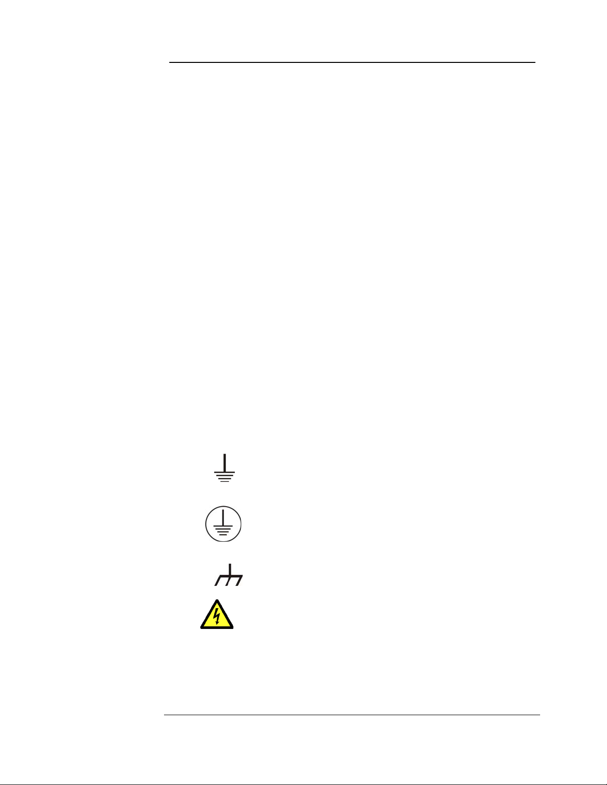
Symbols on equipment...........................................................................................................................8
Other Information ........................................................................................................................................ 8
Cleaning & decontamination..................................................................................................................8
Technical assistance / Authorized Service Centers ............................................................................ 9
Accessory interconnection and use....................................................................................................... 9
Intermittent operation limits.................................................................................................................. 9
Installation requirements .......................................................................................................................9
Unpacking the unit .................................................................................................................................. 9
Pollution Degree II...................................................................................................................................9
Power requirements ............................................................................................................................... 9
Environmental conditions....................................................................................................................... 9
Declaration of Conformity.........................................................................................................................10
1........................................................................................................................................................................11
Instrument Overview .....................................................................................................................................11
Front panel controls ..................................................................................................................................11
Test lead connections .......................................................................................................................13
On-line labels .........................................................................................................................................14
Safety precautions for setup................................................................................................................14
Initial tester power-up and checkout .................................................................................................15
Using the footswitch..............................................................................................................................15
2........................................................................................................................................................................17
Test sequence, voltages & applicable standards.......................................................................................17
Recommended testing sequence.............................................................................................................17
1. Coil Resistance test...........................................................................................................................17
2. Megohm test......................................................................................................................................17
3. Principles of the Dielectric Absorption (DA) test ..........................................................................17
4. Principles of the Polarization Index (PI) test.................................................................................17
5. DC HiPot test.....................................................................................................................................18
6. Surge test...........................................................................................................................................18
Recommended test voltages – HiPot and Surge tests ....................................................................18
Applicable Standards.............................................................................................................................20
3........................................................................................................................................................................21
Coil Resistance testing...................................................................................................................................21
Principles of Coil Resistance testing........................................................................................................21
Other Important Safety warnings .......................................................................................................21
Resistance Test Display ........................................................................................................................22
Resistance test checklist.......................................................................................................................22
Auto ranging Resistance measurement algorithm...........................................................................23
Saving & recalling measurements ......................................................................................................24
Indications of problems in a motor.....................................................................................................24
4........................................................................................................................................................................25
Principles and theory of DC testing.............................................................................................................25
Principles of DC testing.............................................................................................................................25
5........................................................................................................................................................................29
Performing high voltage DC tests................................................................................................................29
Other Important Safety warnings .......................................................................................................29
The test display ..........................................................................................................................................30

2/24/2010 | 71-018 V11 EN
D12R, D6R, D3R Users Manual
4
High voltage DC test checklist .............................................................................................................31
DC testing ...............................................................................................................................................31
Full DC testing of a motor....................................................................................................................31
Performing only a Megohm test.....................................................................................................33
Performing only DC over voltage test (DC HiPot test).....................................................................33
Sample data showing good & poor insulation ..................................................................................34
Storing the test results in memory ....................................................................................................34
Using the footswitch..............................................................................................................................34
The HiPot over current trip indicator.................................................................................................35
Effects of temperature..........................................................................................................................35
Step Voltage test ...................................................................................................................................35
Step Voltage test procedure ................................................................................................................35
7........................................................................................................................................................................37
Performing Surge tests.................................................................................................................................37
Surge test display ......................................................................................................................................37
Other Important Safety warnings .......................................................................................................37
Surge test setup ....................................................................................................................................38
480V three phase motor check list.....................................................................................................39
Single coil surge test and set-up ........................................................................................................40
Example: Comparison to a master coil ..........................................................................................42
8........................................................................................................................................................................43
Surge test applications..................................................................................................................................43
Maintenance testing ..................................................................................................................................43
Application Notes...................................................................................................................................44
Single phase motors and two terminal devices................................................................................44
Determination of a fault...................................................................................................................44
Form coils ...............................................................................................................................................45
Determination of a fault...................................................................................................................45
Notes and tips for form coils...........................................................................................................45
Three phase motors..............................................................................................................................46
Determination of a fault...................................................................................................................46
Two or more single coils ......................................................................................................................46
Determination of a fault...................................................................................................................47
Notes and precautions for two single coils ...................................................................................47
Wound rotor motors .............................................................................................................................47
Determination of a fault...................................................................................................................48
Synchronous motor/generator............................................................................................................48
Determination of a fault...................................................................................................................48
Pole piece fault ......................................................................................................................................48
Stator winding fault ..............................................................................................................................48
Chiller motor testing .............................................................................................................................49
Field coils ................................................................................................................................................49
DC motor/generators............................................................................................................................49
Armatures...............................................................................................................................................49
Bar-to-Bar Surge test .....................................................................................................................49
Span testing .......................................................................................................................................49
Determination of a fault...................................................................................................................50
Testing large AC stators/motors .........................................................................................................52
Notes and tips for large AC stator/motors....................................................................................52
Rotor loading (coupling) when testing assembled motors..............................................................52
Testing assembled motors from the switchgear ..............................................................................54
Transformers .........................................................................................................................................54
Single phase transformers ..............................................................................................................55
Three phase transformers...............................................................................................................55
Determination of a fault...................................................................................................................55
9........................................................................................................................................................................57
Documenting tests.........................................................................................................................................57

2/24/2010 | 71-018 V11 EN
D12R, D6R, D3R Users Manual
5
Store........................................................................................................................................................57
Store Resistance data...........................................................................................................................58
Store HiPot and PI data .......................................................................................................................58
Store Surge data ...................................................................................................................................58
Recall .......................................................................................................................................................59
Recall Resistance data ..........................................................................................................................60
Recall HiPot data ...................................................................................................................................60
Recall Surge data ..................................................................................................................................60
Print.........................................................................................................................................................61
Clear ........................................................................................................................................................61
Erase........................................................................................................................................................61
Compatible printer information...........................................................................................................62
Version 3 firmware ...............................................................................................................................62
Supplement 1 .................................................................................................................................................63
PP130/PP230 power pack...........................................................................................................................63
Important safety information...................................................................................................................63
Other Important Safety warnings .......................................................................................................64
Instrument notices ................................................................................................................................64
Emergency Shut-Off Button................................................................................................................65
Initial set-up ...........................................................................................................................................65
Power pack resistance testing.............................................................................................................66
Three-phase test lead ..........................................................................................................................66
Output configuration .............................................................................................................................66
Operating and shipping position..........................................................................................................66
Power pack operation ...............................................................................................................................67
Surge testing..........................................................................................................................................67
DC HiPot testing ....................................................................................................................................68
Lead connection.....................................................................................................................................69
Single phase lead connections.............................................................................................................69
Note regarding 220/240 VAC units....................................................................................................69
Lifting the instrument...........................................................................................................................70
Supplement 2 .................................................................................................................................................71
PP185 power pack ........................................................................................................................................71
Important safety information...............................................................................................................71
Other Important Safety warnings .......................................................................................................72
Instrument notices ................................................................................................................................72
Emergency Shut-Off Button................................................................................................................73
Initial set-up ...........................................................................................................................................73
Power pack resistance testing.............................................................................................................74
Three-phase test lead ..........................................................................................................................74
Output configuration .............................................................................................................................74
Operating and shipping position..........................................................................................................74
Surge testing..........................................................................................................................................75
DC HiPot Testing........................................................................................................................................76
Sample data showing good & poor insulation ..................................................................................77
Storing the test results in memory ....................................................................................................78
Using the footswitch..............................................................................................................................78
The HiPot overcurrent trip indicator ..................................................................................................78
Effects of temperature..........................................................................................................................78
Armature Testing ..................................................................................................................................79
Bar-to-bar testing/armature testing..................................................................................................79
Bar-to-bar testing with the PP85......................................................................................................80
Determination of a bar-to-bar fault ..............................................................................................80
Armature application recommendations............................................................................................81
Three phase lead connection...............................................................................................................81
220/240 V AC Units..............................................................................................................................81
Lifting the instrument...........................................................................................................................82

2/24/2010 | 71-018 V11 EN
D12R, D6R, D3R Users Manual
6
Supplement 3 .................................................................................................................................................83
PP40 power pack...........................................................................................................................................83
Important safety information...............................................................................................................83
Other Important Safety warnings .......................................................................................................84
Emergency Shut-Off Button................................................................................................................85
Initial set-up ...........................................................................................................................................85
Output configuration .............................................................................................................................85
Power pack operation ...............................................................................................................................86
Surge testing..........................................................................................................................................86
DC HiPot testing ....................................................................................................................................87
Note regarding 220/240 VAC units....................................................................................................88
Output configuration .............................................................................................................................88
Operating and shipping position..........................................................................................................88
Lifting the instrument...........................................................................................................................89
Supplement 4 .................................................................................................................................................91
AT101D Bar-to-bar armature testing .......................................................................................................91
Other Important Safety warnings .......................................................................................................91
Operation ................................................................................................................................................93
Determination of a fault .......................................................................................................................94
Application recommendations..................................................................................................................95
Specifications for the AT101D Bar-to-bar armataure testing accessory ....................................95
Appendix A Winding Faults...........................................................................................................................97
Appendix B Troubleshooting ........................................................................................................................99
Self help and diagnostics..........................................................................................................................99
Step #1: Basic information ................................................................................................................99
Step #2: Applications or service problem?......................................................................................99
Applications: What to do first! ................................................................................................................99
Other Important Safety warnings .................................................................................................... 100
Common application problems......................................................................................................... 101
Service: What to do first? ................................................................................................................ 102
Open condition display....................................................................................................................... 102
HiPot display checks........................................................................................................................... 103
HiPot over current trip check ........................................................................................................... 103
Open ground check ............................................................................................................................ 104
Limited output surge waveform....................................................................................................... 104
Warranty return...................................................................................................................................... 104
Appendix C Technical specifications and calibration.............................................................................. 107
Technical specifications...................................................................................................................... 107
Accuracy of measurements - Coil Resistance test........................................................................ 108
Testing Accuracy - HiPot Measurements....................................................................................... 108
Voltage measurement accuracy – Surge (D12R) .......................................................................... 108
Voltage measurement accuracy – Surge (D6R/D3R) ................................................................... 108
Calibration information...................................................................................................................... 108
Index.............................................................................................................................................................. 109

2/24/2010 | 71-018 V11 EN
D12R, D6R, D3R Users Manual
7
Preface
Important safety information
General Safety Precautions
Note: The general safety information presented here will be for both operating and service
personnel. Specific warnings and cautions will be found throughout this manual where they
apply.
Note: If the equipment is used in any manner not specified by Baker Instrument Company,
an SKF Group Company, the protection provided by the equipment may be impaired.
Safety term definition
DANGER: Indicates a hazardous situation which, if not avoided, will result in death or serious
injury.
WARNING: Indicates a hazardous situation which, if not avoided, could result in death or
serious injury.
CAUTION: Indicates a hazardous situation, which, if not avoided, could result in minor or
moderate injury.
NOTICE: “NOTICE” is the preferred signal word to address practices not related to personal
injury.
Other Important Safety warnings
Failure to follow these precautions could result in severe electrical shock or death.
1) Never attempt a two-party operation. Always know what test is being performed
and when. FOR EXAMPLE: DO NOT adjust test leads when footswitch is being
operated. Leads will have live voltage and severe electric shock may result.
2) For capacitor-started motors or systems with surge arrestors/power factor
capacitors, be sure to disconnect all capacitors from the test circuit before testing.
Danger
High Voltage
To prevent serious injury or death:
-Do not use in explosive atmospheres.
-Do not contact test leads or device being testing
while test is in progress or during discharge period.
-Do not connect test leads to live circuits.
Read and follow safety precautions and safe operating
practices in operator manual. Do not exceed maximum
operating capabilities of this instrument.

Safety equipment warnings and CE compliance statements
2/24/2010 | 71-018 V11 EN
D12R, D6R, D3R Users Manual
8
3) Upon completion of a DC High Potential, Megohm, Polarization Index, Step Voltage,
Dielectric absorption, or Continuous Ramp test, before disconnecting the test leads,
short the winding, motor, etc., to ground and allow time for discharge. If this is not
done, voltage may still be active on leads and tested components.
4) Make sure the tester leads are disconnected before the motor is energized or
powered up.
5) Do not remove the product covers or panels or operate the tester without the
covers and panels properly installed. Components on inside of tester carry voltage
for operation and if touched can render a shock.
6) Use appropriate safety equipment required by your organization, including high
voltage globes and eye protection.
7) Repair Parts Warning : Defective, damaged, or broken test leads must be
replaced with factory-authorized parts to ensure safe operation and maintain
performance specifications.
8) Ground the product : This product is grounded through the grounding conductor
of the power cord. To avoid electrical shock, plug the power cord into a properly
wired/grounded receptacle before connecting the product test leads.
Danger from loss of ground – Upon loss of the protective ground connection,
all accessible conductive parts, including knobs and controls that may appear
to be insulated, can cause an electric shock!
9) This instrument is NOT waterproof or sealed against water entry.
10) The unit is for indoor use. If used outdoors, the unit must be protected from rain,
snow and other contaminants.
Symbols on equipment
Protective conductor terminal. Located beside black ground test lead
on front panel of instrument.
Earth (ground) terminal
Frame or chassis terminal. Located on rear panel of instrument by
ground terminal.
Warning about hazardous voltage and risk of severe electrical shock or
death. Located beside each red test lead on front panel of instrument.
Other Information
Cleaning & decontamination
The D3R/D6R/D12R should be kept clean and in a dry environment. To clean the unit, power
down and unplug the instrument. Wipe with a clean water dampened cloth. Do not submerge

Safety equipment warnings and CE compliance statements
2/24/2010 | 71-018 V11 EN
D12R, D6R, D3R Users Manual
9
in water or other cleaners or solvents. To clean the screen, take a soft water dampened cloth
and gently wipe the surface.
Technical assistance / Authorized Service Centers
See our website at www.bakerinst.com for technical assistance/authorized service center
information. This information will be marked with an asterisk.
Accessory interconnection and use
The D3R/D6R/D12R are equipped with a footswitch standard. Other accessories, such as the
AT101ZTX and safety lights are optional. Please see details about these accessories in later
chapters in this manual.
Intermittent operation limits
At this time there are no intermittent operation limits to the use of the AWA unit.
Installation requirements
The unit may be operated
1) Flat on the bottom of the unit,
2) Flat on the back of the unit, or
3) Held at an angle using the rotating handle.
There are no ventilation requirements.
The unit is intended for use in Installation Category II (Portable Equipment) areas and
pollution Degree II Environments where occasional non-conducting condensing pollution can
be encountered.
Unpacking the unit
Carefully remove the following items from the shipping boxes.
D3R, D6R or D12R
Power cord
Operation manual
Pollution Degree II
(From IEC 61010-1 3.6.6.2) Only non-conductive pollution occurs. However, temporary
conductivity caused by condensation is expected.
Power requirements
Using the provided AC power cord, connect the unit to a grounded AC power source. The
unit’s power requirements are 100-240VAC, 50-60 Hz, 2 amps AC maximum current draw.
The unit is fused using 2.5A fast blow fuses. Replace fuses with like type and rating.
Environmental conditions
1) The unit has been tested for use up to 2000 m.
2) The tester should only be operated in temperatures ranging from 41 to 104
degrees Fahrenheit (5° C to 40° C).
3) This unit is for use at a maximum relative humidity of 80% for temperatures up to
31 °C decreasing linearly to 50% relative humidity at 40°C. This unit is intended for
Installation Category II in a Pollution Degree II environment.

Safety equipment warnings and CE compliance statements
2/24/2010 | 71-018 V11 EN
D12R, D6R, D3R Users Manual
10
Declaration of Conformity
Manufacturer’s Name & Address:
Baker Electrical Instrument Company, an SKF Group Company,
4812 McMurry Ave
Fort Collins, CO 80525
USA
Equipment Description: Testers for Surge, DC Hi-Pot, and Winding Resistance of motors.
Equipment Model Designations: D3R, D6R, D12R.
Application of Council Directive 72/23/EC on the harmonization of the laws related to Member
States relating to electrical equipment designed for use within certain voltage limits, as
amended by: Council Directive 93/68/EC and Council Directive 2004/108/EC on the
approximation of the laws related to Member States relating to the electromagnetic
compatibility, as amended by: Council Directive 93/68/EC. Note: due to the phenomena being
observed and the material properties being measured, this equipment does radiate radio
frequency energy while in the active test mode.
Referenced Safety Standards:
EN 61010-1
Referenced EMC Standards:
EN 61326:2001
EN 55011 Class A
EN 61000-3-2
EN 61000-3-3
EN 61000-4-2
EN 61000-4-3
EN 61000-4-5
EN 61000-4-5
EN 61000-4-6
EN 61000-4-11
I, the undersigned, hereby declare that the equipment specified above conforms to the above
Directives and Standards.
Signature:
Printed Name: John S. Wilson
Title: Manager, Standard Products.

2/24/2010 | 71-018 V11 EN
D12R, D6R, D3R Users Manual
11
1
Instrument Overview
Front panel controls
1) Printer port
Parallel port for printing waveforms and summaries displayed by the Digital Tester. This port
may also be used for interfacing with the Motor Test Acquisition for Windows program (MTA
for Windows) on a personal computer.
2) Aux port
Auxiliary port for using the Digital Tester with a 30kV power pack, for high voltage testing.
(Refer to Supplement 1: PP130/PP30 Power Pack)
3) Line in
AC power entry.
4) On/Off
The on off switch for the unit. On/off switch is combined with the AC power entry and a fuse.
5) Function keys
Function keys for data collection, recall, clearing and printing of tests.
6) CRT display
The Cathode Ray Tube (CRT) is the location where the tester displays test information. At the
Top, menus corresponding to the four function keys above the CRT are shown. The main
portion of the screen displays the waveforms being measured and/or recalled with
corresponding graticules for reference. The bottom portion shows the volts/division for the
waveform, the name of the test on display, and the micro-seconds/division (micro-
amps/division for HiPot tests).
7) Open ground warning light
When the AC line source is not properly grounded, the red Open Ground light will illuminate.
The test set will power up, but high voltage will be withheld by internal electronics.
8) HiPot trip warning light
This lamp illuminates to indicate a DC HiPot trip circuit has stopped the test. The red lamp will
stay illuminated until the test button is released.
9) Intensity
Rotation of this control will adjust the intensity or brightness of the display.

Instrument Overview
2/24/2010 | 71-018 V11 EN
D12R, D6R, D3R Users Manual
12
10) Vertical position
This control adjusts the up or down positioning of the surge wave pattern. Optimum
positioning is usually on the center of one major graticule line below center for surge testing.
11) Horizontal position
This control adjusts the side to side positioning of the surge wave pattern. A trace beginning
at the far left is suggested for surge testing.
12) Function selector
This control selects the type of test to be performed: Surge Testing, HiPot testing with 4
different current sensitivities, resistance testing for each of the three leads, AT101 testing,
and auxiliary/power pack surge/HiPot testing.
AT101: This position is used when using the Baker Instrument Company, an SKF Group
Company, Model At101 Bar-to-Bar Armature Test Accessory. Note: The Zero Start Interlock
is disabled when this function is selected and the Footswitch is depressed.
AUX: The auxiliary position is for use with a 30kV Power Pack. The display will also show
wave patterns from accessory units in this position.
Surge: This position selects the Surge Test. The name of the test and the microseconds
per division measured is displayed on the lower portion of the CRT for reference. A digital
readout for the peak voltage of the test is also displayed in the upper right portion of the
screen for reference.
HiPot- uA/div: This position is used for DC HiPot testing. The name of the test is
displayed on the lower portion of the CRT for reference. A digital readout for the leakage
current (in micro-amps) of the test and the resultant resistance in mega-ohms is also
displayed on the screen for reference. There are four positions associated with the HiPot test.
The four positions are 100uA/div, 10uA/div, 1uA/div, and 0.1uA/div. The chosen micro-amps
per division setting is displayed on the lower right portion of the CRT for reference during

Instrument Overview
2/24/2010 | 71-018 V11 EN
D12R, D6R, D3R Users Manual
13
testing. The position of the function knob in one of the above current ranges also
automatically selects the overcurrent trip point which will be ten time the settings or 900uA,
90uA, 90uA, or 0.9uA, respectively, for each of the sensitivity ranges above.
Resistance Lead 1-2: This position selects the storage location for a resistance test. This
does not select the actual leads connected to the D12R/D6R/D3R.
Resistance Lead 2-3: This position selects the storage location for a resistance test. This
does not select the actual leads connected to the D12R/D6R/D3R.
Resistance Lead 1-3: This position selects the storage location for a resistance test. This
does not select the actual leads connected to the D12R/D6R/D3R.
13) Volts/Div
This control sets the sensitivity of the display or scale factor in volts per division for both the
Surge and DC HIPOT traces. There are four settings corresponding to the tester. For example
the D12R Volts/Div are 500, 1000, 2000, and 3000 volts. Note: this knob setting does not
limit the output voltage of the tester.
14) Seconds/Div
This control adjusts the seconds per division or sweep rate of the trace on the horizontal axis
of the surge display. There are ten settings corresponding to 2, 6, 10, 20, 60, 100, 200, 500,
600, 1000, 2000 micro-seconds per division. The seconds per division setting is displayed on
the lower right portion of the display for the reference during Surge Testing. This control will
have the effect of zooming in or out on the wave pattern.
15) Leads energized indicator light
This indicator light will illuminate when voltage is applied during a test.
V fast up
When pressed, this control will increase the applied voltage to a motor at an increasing rate of
approximately 1000V/second.
V slow up
When pressed, this control will increase the applied voltage to a motor at a slower but still
increasing rate of 33.3V/second.
V slow down
When pressed, this control will decrease the applied voltage to a motor at a slow rate of
approximately 250V/second.
16) Test button
The test button activates the high voltage output of the tester. One of the selected modes,
surge or HIPOT, will be enabled and a voltage will be impressed on the device being tested.
This button automatically disengages when released and must be held in during the whole
length of the test unless the Footswitch is being used.
17) Test lead select switch
Test lead connections
Switch position Test lead #1 Test lead #2 Test lead #3 Ground
Surge lead 1 Hot Ground Ground Ground
Surge lead 2 Ground Hot Ground Ground
Surge lead 3 Ground Ground Hot Ground
HiPot Hot Open Open Ground
All leads ground Ground Ground Ground Ground
18) Footswitch connector
A footswitch may be connected to this socket which is in parallel to the Test button. The
footswitch will operate the tester in a manner identical to the Test button, freeing the users
hand from having to operate the Test button.
19) Test leads
Test leads #1, #2, and #3 (red) and grounds (black) are provided for contact to the windings.
Test leads are insulated to 40 kV.
20) Resistance test leads
There are two sets of test leads, two wires each lead, that are provided to make contact to
the windings of a motor. Each set of leads contains a current carrying lead and a high
impedance sense lead.

Instrument Overview
2/24/2010 | 71-018 V11 EN
D12R, D6R, D3R Users Manual
14
On-line labels
1) Menu bar
The Menu Bar presents various options for recalling data, storing data, printing data, and
clearing the display.
2) Message area
Operation and print message are displayed in this area.
3) Wave pattern display area/record choice area
During testing, Surge wave patterns and DC tests potentials are graphically displayed here.
Major and minor graticules are provided. During internal memory access, Record and Lead
locations are displayed here.
4) Seconds/Div or micro Amps/Div Setting
Seconds/division is displayed here during Surge Testing. The micro amps/division setting is
displayed here during HiPot Testing.
Safety precautions for setup
−There are no ventilation requirements. The unit is intended for use in Installation
Category II (Portable Equipment) areas and pollution Degree II Environments where
occasional non-conducting condensing pollution can be encountered.
−Do not stack objects on or near the DR unit.
−To prevent shock hazard, do not expose the DR unit to rain, snow, or moisture.
Avoid locations with high levels of dirt or dust.
The unit may be operated
4) Flat on the bottom of the unit,
5) Flat on the back of the unit, or
6) Held at an angle using the rotating handle.

Instrument Overview
2/24/2010 | 71-018 V11 EN
D12R, D6R, D3R Users Manual
15
Initial tester power-up and checkout
Upon powering up the D3R/D6R/D12R the digital control system begins a self check. Memory
is tested, HiPot trips circuits armed, high voltage power supplies disabled, etc. If nothing is
visible on the screen, turn the Intensity control to the center of the knob’s range. If no image
is visible, verify good power is available to the unit and verify the fuses aren’t blown.
Each Baker Instrument Company, an SKF Group Company, tester incorporates a supply
ground detection circuit. The ground detection circuit is active immediately upon power up on
and assures a positive ground is available to the tester. If the instrument is not properly
grounded, the Open ground indicator will light and testing cannot proceed. Check the supply
to the tester (broken ground, bad extension cord, excessive ground to neutral voltage) and
assure that a low impedance ground is provided to the unit.
If the instrument does not appear to be working properly, contact Baker Instrument
Company, an SKF Group Company’s Service Department. Refer to Warranty Notes and
Appendix B: Troubleshooting for more information.
Using the footswitch
The Digital tester can be equipped with a footswitch that allows hands free operation of the
instrument. For example it is used to help eliminate the display effect of rotor loading, by
allowing the operator to spin the rotor of the equipment under test.

Instrument Overview
2/24/2010 | 71-018 V11 EN
D12R, D6R, D3R Users Manual
16

2/24/2010 | 71-018 V11 EN
D12R, D6R, D3R Users Manual
17
2
Test sequence, voltages &
applicable standards
Recommended testing sequence
In order to test motors adequately and to have effective predictive maintenance programs,
Baker Instrument Company, an SKF Group Company, suggests using a specific test sequence.
The general idea is to perform the test sequence as a series of progressively more rigorous
tests, accepting the idea that if a test fails, troubleshooting and repair should begin at that
time. Further, more rigorous testing should only commence after satisfactory diagnosis and/or
repair.
The suggested testing sequence is: (1)Resistance test, (2)Meg-ohm, (3)HiPot and finally (4)
Surge.
1. Coil Resistance test
A coil resistance test looks for resistance imbalance between phases, discrepancies between
measured resistance values, previous measurements and nameplate values. If a problem is
found, the motor should be inspected for the cause of the discrepancies. Typical problems that
may exist are 1) hard shorts to the motor’s core, 2) hard shorts between coils either within
the same phase or between phases, 3) coils rewound with the improper gauge wire, 4) loose
or corroded connections. Further HiPot or Surge testing is not necessary until the resistance
measurement is acceptable.
2. Megohm test
A megohm test is performed using a test voltage based on the operating voltage of the motor
and the appropriate standards/company testing guidelines. Look for an unusually low
megohm value when compared to previous measurements or industry accepted limits for the
type of insulation in the motor. If a low megohm value is measured, the motor should be
inspected for ground wall insulation damage. Some part of the ground wall insulation has
failed. Possible problems include: 1) slot liner insulation or enamel wire insulation may be
burned or damaged, 2) the motor might be full of dirt, carbon dust, water or other
contaminates, 3) connections to the actual coils may be bad, 4) wrong insulation may have
been used to connect the coils to the motor’s junction box, etc. No further testing is necessary
until the reason for low meg-ohm readings is found and corrected.
3. Principles of the Dielectric Absorption (DA) test
The Dielectric Absorption (DA) test is essentially a short-duration PI test and is usually
intended for smaller motors. Larger motors whose insulation does not easily polarize are also
good candidates for the DA test. Other than the shorter test time, all other principles are the
same as the PI test, explained in the next section.
While the PI test is recommended only for motors 200 horsepower or greater, the DA test is
useful for motors in approximately the 50 to 200 horsepower range. The DA value is the ratio
of the ground wall insulation resistance (IR) at 3 minutes to the IR value at 30 seconds.
4. Principles of the Polarization Index (PI) test
The Polarization Index test (PI test) is the most confusing HVDC test in use due to the
subtleties in the interpretation of the results. The PI test is performed in order to
quantitatively measure the ability of an insulator to polarize. When an insulator polarizes, the

Test Sequence, voltage & applicable standards
2/24/2010 | 71-018 V11 EN
D12R, D6R, D3R Users Manual
18
electric dipoles distributed throughout the insulator align themselves with an applied electric
field. As the molecules polarize, a “polarization current”, also called an absorption current, is
developed that adds to the insulation leakage current. This additional polarization current
decreases over time and drops to zero when the insulation is completely polarized.
The PI result becomes confusing when attempting to attribute variations in the PI value to the
polarizability of the insulator or other affects such as humidity or moisture, surface leakage or
instrument error. The result is even more confusing when attempting to reconcile a PI of 1
when one is expecting some other PI.
The PI test is typically performed at 500, 1000, 2500 or 5000 volts, depending on the
operating voltage of the motors being tested and takes 10 minutes to complete. The PI value
is calculated by dividing the insulation resistance at 10 minutes by the resistance at 1 minute
as shown below:
In general, insulators that are in good condition will show a “high” polarization index while
insulators that are damaged will not. IEEE 43-2000 recommends minimum acceptable values
for the various thermal classes of motor insulation.
Unfortunately, most the insulating materials developed recently (last 20 years) do not
easily polarize. For example the newer inverter grade wires and epoxy resins do not readily
polarize. As recommended in IEEE 43-2000, if the one-minute insulation resistance is greater
than 5000Mohms, the PI measurement may not be meaningful.
To address the situation where the PI may not be meaningful, the Dielectric Absorption
(DA) is widely used instead. The DA is the IR value at 3 minutes divided by the IR value at 30
seconds. The motivation for even doing the DA test is to reduce the test time to 3 minutes
instead of 10 minutes for the PI test when the PI test may not be worthwhile. To date there
are no accepted values for the DA. However, some usefulness can be obtained by trending the
DA value over time.
5. DC HiPot test
A DC HiPot test is performed using a test voltage that is substantially higher than the
Megohm Test, but, once again, based on operating voltage of the motor and the appropriate
standards/company guidelines. Look for unusually high leakage currents or a leakage current
that doesn’t stay constant or intermittently jumps up and down. Breakdowns or high leakage
currents are an indication of damaged ground wall insulation. Inspect the motor’s slot liner,
wedges, conductors between the junction box and the coils, etc.
6. Surge test
A Surge test is performed on each phase of the motor, again using an appropriate test
voltage based on the operating voltage of the machine and the appropriate
standards/company guidelines. Look for a jump to the left of the surge waveform pattern as
the test voltage is increased. This is the signature of the turn – to – turn short. If a jump is
observed, an inspection of the motor should be made to look for damaged insulation between
adjacent conductors. The insulation may be hard to see visibly, so the motor may have to be
disassembled to find the problem. If no jump in the wave patterns is observed, the likelihood
of motor failure due to insulation failure is greatly reduced.
Recommended test voltages – HiPot and Surge tests
Recommended test voltages for HiPot and Surge testing a motor, generator or transformer
are twice the AC line voltage plus 1000 volts. This test voltage is consistent with NEMA MG-
1, IEEE 95-1977 (for test voltage greater than 5000 volts), and IEEE 43-2000 (test voltages
less than 5000V).
View the tables below for a comparison of IEEE 95, EASA DC HiPot, IEEE522 Surge Testing,
IEC 34-15 and Baker recommended testing voltages. Note: Representations of motors are
min)1(
min)10(
IR
IR
PI =

Test Sequence, voltage & applicable standards
2/24/2010 | 71-018 V11 EN
D12R, D6R, D3R Users Manual
19
listed. The formulas to calculate voltages are also listed so that test voltage of any size motor
can be calculated.
IEEE 95-1977
EASA DC HiPot
V Line Per Unit New 3.4*Vline +1700 In Service 65% of New
480 392 3332 2165.8
575 469 3655 2375.75
600 490 3740 2431
2300 1878 9520 6188
4160 3397 15844 10298.6
6900 5634 25160 16354
13800 11268 48620 31603
IEEE 522 Surge Testing
V Line Per Unit New 3.5* pu In Service 75% of New
480 392 1372 1029
575 469 1643 1232
600 490 1715 1286
2300 1878 6573 4930
4160 3397 11888 8916
6900 5634 19718 14789
13800 11268 39437 29578
IEC 34-15
V Line Per Unit 1.2 x 50 4E +5000 0.2us 65%
480 392 6920 4498
575 469 7300 4745
600 490 7400 4810
2300 1878 14200 9230
4160 3397 21640 14066
6900 5634 32600 21190
13800 11268 60200 39130
Baker Instrument Company, an SKF Group Company
V Line Per
Unit
In Service 2E + 1000
480 392 1960
575 469 2150
600 490 2200
2300 1878 5600
4160 3397 9320
6900 5634 14800
13800 11268 28600
V Line Per Unit Min Test
Vline*1.25
x 1.7
Max Test
Vline * 1.5
x 1.7
480 392 1020 1224
575 469 1222 1466
600 490 1275 1530
2300 1878 4888 5865
4160 3397 8840 10608
6900 5634 14663 17595
13800 11268 29325 35190

Test Sequence, voltage & applicable standards
2/24/2010 | 71-018 V11 EN
D12R, D6R, D3R Users Manual
20
Note: Although the CRT display is accurately calibrated, it is not possible to set the voltage
exactly. It is suggested that the test voltages be rounded off to the nearest graticule
discernable on the display.
Applicable Standards
−EASA Standard AR100-1998 Recommended Practice for the Repair of Rotating Electrical
Apparatus
−IEC 60034-1 (1999-08) Consolidated Edition, Rotating Electrical Machines Part I: Rating
& Performance Ed. 10.2
−IEEE 43-2000 Recommended Practice for Testing Insulation Resistance of Rotating
Machinery
−IEEE 95-1977 Guide for Insulation Maintenance of Large AC Rotating Machinery
−IEEE 112-1991 Test Procedures for Polyphase Induction Motors and Generators
−IEEE 113-1985 Guide on Test Procedures for DC Machines
−IEEE 115-1983 Test Procedures for Synchronous Machines
−IEEE 429-1972 Evaluation of Sealed Insulation Systems for AC Electric Machinery
Employing Form-Wound Stator Coils
−IEEE 432-1992 Guide for Insulation Maintenance for Rotating Electrical Machinery (5hp
to less than 10,000hp)
−IEEE 434-1973 Guide for Functional Evaluation of Insulation Systems for Large High-
Voltage Machines
−IEEE 522-1992 Guide for Testing Turn-To-Turn Insulation on Form-Wound Stator Coils
for Alternating-Current Rotating Electric Machines.
−NEMA MG1-1993 Motors & Generators
Reprints or EASA standards are available from:
www.easa.com
1331 Baur Boulevard
St. Louis, MO 63132
Phone: 314-993-2220
FAX: 314-993-1269
Reprints of IEC standards are available from:
International Electrotechnical Commission (IEC)
www.IEC.ch
Reprints of IEEE standards are available from:
IEEE Customer Service
445 Hoes Lane
P.O. Box Piscataway, NJ 08855-1331
Phone: 1-800-678-IEEE
Fax: 908-981-9667
www.ieee.org
Reprints of NEMA standards are available from:
National Electrical Manufacturers Association (NEMA)
Global Engineering Documents
Phone: 1-800-854-7179
International: 303-379-2740
This manual suits for next models
2
Table of contents
Other Baker Instrument Company Test Equipment manuals