iPA SMART MUTT 9004M User manual

Innovative Products of America®Incorporated
888-786-7899 • 234 Tinker Street, Woodstock, NY 12498 • www.ipatools.com
A Portable Unit for Commercial Trailer Lighting and ABS
OPERATOR’S MANUAL
#9007M
SMART MUTT®
Mobile Universal Trailer Tester
MAD
E
IN
USA

2
LETTER FROM THE PRESIDENT OF IPA®
My name is Ian Vinci and I would like to thank you for your interest in our products.
In today’s world, we have all experienced the lack of service and consideration
demonstrated by many companies after you buy their products. They say whatever
they can to make the sale, and then it’s like pulling teeth to get any service response
out of them. I know this myself rsthand and because of this, I want to be sure that your
experience with IPA®meets your expectations and that IPA®never disappoints you with
our service or customer response.
To prove my commitment to you, if for any reason, you are not happy with one of our
products, or more importantly, with the response from our customer service department,
or any member of the IPA®team, I invite you to contact me directly via my email,
to me than the sale itself. We will not be in business for long if we don’t make you
completely happy with our products and service. I want IPA®to be different and be known
for its quality and service.
With that said, please take a look at our product line. You will see innovative rst time
products that were created to help you do your job faster and better than before.
I would also like to invite you to critique our products. If you can think of a better way to
make them or changes that will make them work better, please contact me directly and I
will be sure to look into it. If you have an innovation and would like some
feedback, give me a call.
From all of us at IPA®, we thank you for taking the time to review our product line and wish
you and your family the very best of everything.
Ian Vinci
President
IPA®
www.ipatools.com
Toll Free: 888-786-7899
Phone: 845-679-4500
Fax: 845-679-4600
(OEM) Original Equipment Manufacturer USA

3
TABLE OF CONTENTS
PART 1: IMPORTANT SAFETY INSTRUCTIONS 4
PART 2: WHAT’S INCLUDED 7
PART 3: CONTROLS AND PANELS 8
3.1 Left and Right Side Panels 8
3.2 Electrical Control Panel 9
PART 4: SETUP 10
4.1 Choosing a Battery 10
4.2 Axle and Wheel Installation 11
PART 5: PRETESTING CHECKLIST 12
5.1 Cable Testing Procedure 12
PART 6: GENERAL CONTROLS & OPERATION 13
6.1 Initial Startup and Shutdown 13
6.2 Auto Shutdown Feature 14
6.3 Using the 3-Button Remote Control 14
6.4 Using the 12-Button Remote Control 14
PART 7: ELECTRICAL/LIGHTING TESTING 15
7.1 Selecting a Circuit 15
Auto-Cycle Mode 15
7.2 Ground Integrity Test 16
Establishing a Solid Ground 16
7.3 Fault Indication 17
Open Circuit 17
Crossed Circuits 17
Short/Overloaded Circuit 18
7.4 Activating Hazard Lights 19
7.5 All Circuits On (Override) Mode 20
PART 8: ABS BLINK CODE DIAGNOSTICS 21
8.1 Meritor/WABCO Blink Codes 22
8.2 Haldex Blink Codes 23
8.3 Bendix Blink Codes 28
PART 9: TYPICAL TRAILER WIRING 31
PART 10: MAINTENANCE AND STORAGE 32
PART 11: ADDITIONAL TESTING PROCEDURES 32
PART 12: OPTIONAL ACCESSORIES AND
RELATED PRODUCTS 33
4
PART 1: IMPORTANT SAFETY INSTRUCTIONS
IT IS IMPORTANT TO READ, UNDERSTAND AND FOLLOW ALL SAFETY
MESSAGES AND INSTRUCTIONS PRINTED IN THIS MANUAL AND ON THE
EQUIPMENT BEFORE OPERATING. IF SAFETY INFORMATION IS NOT HEEDED,
SERIOUS INJURY OR DEATH TO THE OPERATOR OR BYSTANDERS MAY OCCUR.
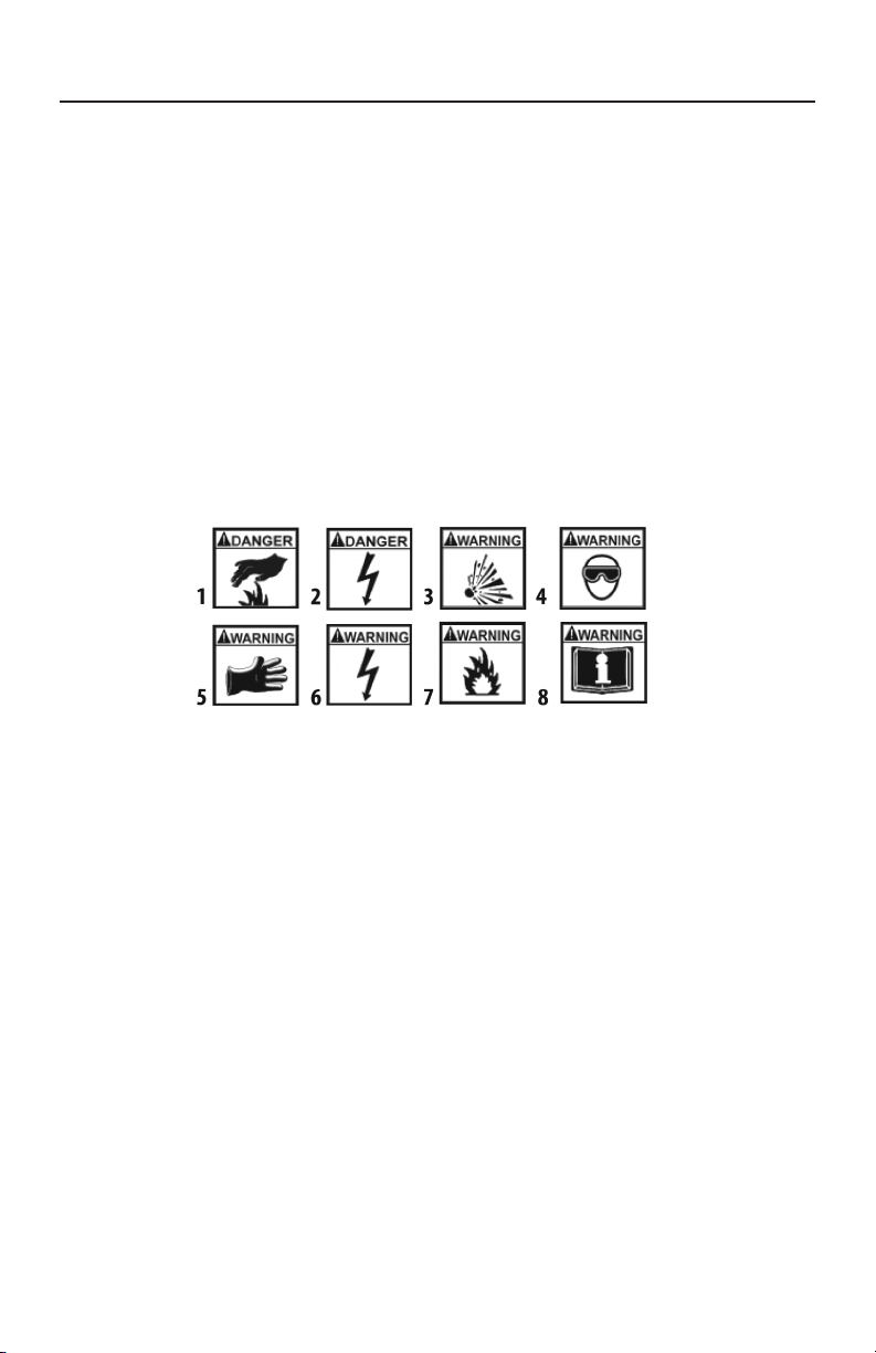
DANGER
Indicates a hazardous situation, if not avoided, will result in death or serious injury.
The possible hazards are shown in the adjoining symbols or explained in the text.
WARNING
Indicates a hazardous situation, if not avoided, could result in death or serious injury.
The possible hazards are shown in the adjoining symbols or explained in the text.
CAUTION
Indicates a hazardous situation, if not avoided, may result in minor or major injury.
The possible hazards are shown in the adjoining symbols or explained in the text.
THE FOLLOWING SAFETY ALERT SYMBOLS ARE USED IN THIS MANUAL.
SYMBOL 1: Potential burn hazard. Sparks from electrical shorts can ignite
ammable liquids such as fuel or oil. Heat from electrical overloads can cause re
hazards.
SYMBOL 2: Potential electrical hazard. Batteries have enough electrical energy
potential to ignite ammable liquids such as fuel or oil. Wire overloads can cause
electrical failures. Shock hazard exists.
SYMBOL 3: Potential explosive air hazard. Pneumatic pressures used with this
equipment can cause explosive failures on damaged equipment.
SYMBOL 4: Potential eye hazard. Wear OSHA approved safety glasses. Battery
acid and high air pressures create hazardous situations for eyes.
SYMBOL 5: Potential chemical burn hazard. Wear protective gloves. Battery acid
is corrosive and can cause skin damage.
SYMBOL 6: Potential electrical hazard. Electrical energy can cause heat and
burn hazards.
SYMBOL 7: Potential re hazard. Use caution with ammable liquids such as fuel
and oil. Electrical shorts can ignite ammable liquids and wiring.
SYMBOL 8: Important information is stated.

5
BATTERY GASES, TESTER PREPARATION
AND TESTER/CHARGER LOCATION
RISK OF EXPLOSION
• Gases produced by a battery are highly explosive.
• Wear safety goggles and protective clothing, both
users and bystanders.
• Use in an area having at least four air changes per hour.
• Read, understand and follow all instructions for charger, battery, vehicle and any
equipment used near battery and charger.
• Do not smoke, strike a match, place metal tools on battery or cause a spark in
the vicinity of the battery. When removing battery cables, remove the ground
cable rst.
• Clean terminals before charging battery. During cleaning, keep corrosive particles
from eyes, nose and mouth. Use baking soda and water to neutralize acid and
help eliminate airborne corrosion.
• Never allow clamps on charger cables to touch each other.
• Do not expose tester or charger to rain, snow, or wet conditions.
• Do not allow battery gases or acid to contact MUTT®cabinet. Do not place
charger directly above or below battery.
• Fill battery to level specied by battery manufacturer using distilled water.
• Do not remove cell caps while charging per manufacturer’s instructions.
• Make sure tester cable clamps make tight connections.
• Battery explosion can cause injury.

6
GENERAL CHARGER USE
RISK OF ELECTRIC SHOCK AND FIRE
• Before connecting charger to unit, make sure
controls are set to OFF.
• Do not remove or bypass the grounding pin.
• Do not operate charger with damaged cord or plug.
Replace cord or plug immediately if damage occurs.
• Position power cord and charger cables away from the hood, doors and hot or
moving engine parts where they could be damaged.
• Unplug power cord by grasping and pulling on the plug, rather than the cord
when disconnecting charger from outlet.
• Charger power cord uses equipment-grounding conductor and a grounding plug.
Plug only into a 120V AC outlet that is correctly installed and grounded in
accordance with all ordinances and local codes.
• Unplug power cord from outlet before cleaning or maintaining tester and charger.
Turning off controls does not reduce the risk of electric shock.
• Do not operate charger after a sharp impact, drop or any other damage. Do not
disassemble charger.
• Use only recommended attachments.
• Do not charge a frozen battery.
• Do not overcharge a battery.
• Use charger only on lead-acid automotive batteries. Do not use charger for
charging dry cell batteries.
• Electric shock or re can cause injury.
RISK OF ENTANGLEMENT
• Keep yourself, clothing and battery charger leads clear of moving parts such as
fan blades, pulleys, hood and doors.
• Moving parts can cause injury.
RISK OF BURNS
• Batteries can produce short circuit current high enough to weld jewelry such
as rings, bracelets and watches. You must remove them before working near
batteries.
• Short circuits can cause injury
DO NOT
Plug Directly Into
AC Wall Outlet

7
PART 2: WHAT’S INCLUDED
5 FT. 7 ROUND PIN CABLE
#7900K-1
INCLUDED PARTS AND ACCESSORIES:
Power
Switch
Ammeter
Mute
Switch
Hazard
Switch
Warning
Indicators
Fuse
Switch
Chassis
Ground Input
7 Round Pin
Cable Output
12V Battery
Charge Input
Control Knob
Electrical
Testing Panel
Handle
Foot
Pneumatic
Wheels
Use the Provided Reference Numbers When Ordering Products and Parts Above
Toll Free: 888-786-7899
REMOTE CONTROL FOB
(Qty. 1 Included)
#MUT-RM3-9007A
10 AMP CHARGER
#KCHG-121001
12-BUTTON REMOTE
CONTROL FOB (Qty. 1 Included)
#MUT-RM12
RAINCOVER
#CVR-0001

8
PART 3: CONTROLS AND PANELS
An overview of the MUTT’s controls, inputs, outputs and their functions.
3.1 LEFT AND RIGHT SIDE PANELS
A. 7 ROUND PIN CABLE TEST INPUT
For testing the integrity of a 7 round pin trailer cable. Can also be used to verify
that the MUTT is operating correctly.
B. 20 AMP INDEPENDENT POWER INPUT
For connecting external 12DC 20 amp max. power supply. (Power supply is an
optional accessory, not for battery charging.)
C. 12V DC BATTERY TRICKLE CHARGE INPUT (CIGARETTE SOCKET)
For connecting the trickle charger to the MUTT’s internal battery (battery not
included).
D. 7 ROUND PIN CABLE OUT TO TRAILER
For connecting 7 round pin trailer to the MUTT to test electrical circuits
E. CHASSIS GROUND INPUT
Insert the supplied ground cable into this socket for trailers using the frame or
body for ground connection instead of the ground pin in the harness.
Left Side Right Side
C D E
AB
9
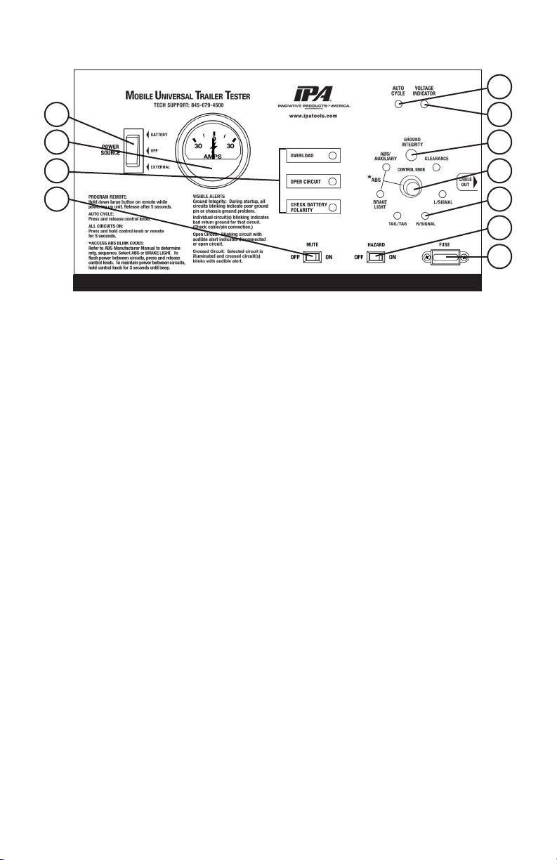
3.2 ELECTRICAL CONTROL PANEL
A. POWER SOURCE SWITCH
Select between Internal Battery, External Power or Power Off.
Center: OFF (battery charge in this position only)
Up: Installed Battery ON
Down: External Power ON (power supply is an optional accessory)
B. BACKLIT 30 AMP AMMETER
Meter shows current draw of a selected circuit up to 30 amps.
C. TROUBLE WARNING INDICATORS
Flashing red LEDs indicate problems that may exist in a selected circuit. This includes
the Overload Indicator, Open Circuit Indicator, and Reversed (Battery) Polarity Indicator.
D. MUTE SWITCH
ON disables sound. OFF enables sound.
E. AUTO CYCLE INDICATOR
Illuminates when Auto Cycle Mode is engaged.
F. VOLTAGE INDICATOR
Shows supplied battery voltage integrity. Operating Voltage Range: 12/24 volt DC.
G. GROUND INTEGRITY
A large green LED above the control knob indicates ground status. Ground
integrity is automatically veried when power is turned on.
H. CONTROL KNOB
Knob activates all electrical test modes and circuits to be diagnosed.
I. CIRCUIT INDICATORS
The small green LEDs illuminate or blink in testing phase.
J. HAZARD SWITCH
Activate the four-way ashers on a trailer.
K. 30 AMP FUSE SOCKET
Overload protection.
A
B
D
Electrical Control Panel
C
F
E
G
H
I
J
K
10
PART 4: SETUP
4.1 CHOOSING A BATTERY
The MUTT®is a 12/24V DC device. Attempting to power
your MUTT®with anything other than a 12 or 24 Volt DC
power source will destroy the internal circuitry and void your
warranty.
(Manufacturer’s Suggested Replacement: Group 31. MUTT®will auto detect 12 or 24
Volts. If 24 volts is required, two smaller 12 volt batteries can be used, but they must
be wired in series.)
• Battery Voltage: 12/24V DC
• Battery Type: Lead Acid
• Battery Compartment Dimensions:
13.5" L x 11" H x 9.25" D
• Battery Protection: Inline 30 amp Fuse for
Overcharge
• Battery must be clean and leak free.
• Identify battery polarity.
• Attach ring terminal (with red heat-shrink) to
positive (+) side and ring terminal (with black
heat-shrink) to negative (-) side. Also see
warning indicators on page 4. Connections
must only be made to clean terminal rings.
• Any loose or corroded connectors may cause
misdiagnosis or result in erroneous readings.
• Use well-charged battery.
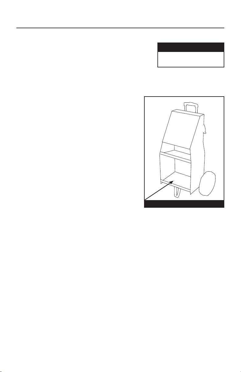
Battery Compartment
DC POWER
Do not plug directly into
AC wall outlet
Other manuals for SMART MUTT 9004M
1
Table of contents
Other iPA Test Equipment manuals

iPA
iPA ALPHA MUTT User manual

iPA
iPA 9101 User manual

iPA
iPA SMART MUTT 9004A User manual

iPA
iPA LIGHT RANGER MUTT 9101 User manual

iPA
iPA Alpha MUTT with ABS User manual

iPA
iPA Alpha MUTT 5700 User manual

iPA
iPA SUPER RANGER MUTT User manual

iPA
iPA SMART MUTT 9004M User manual

iPA
iPA HEAVY RANGER MUTT 9102 User manual

iPA
iPA SMART MUTT 9004A User manual


