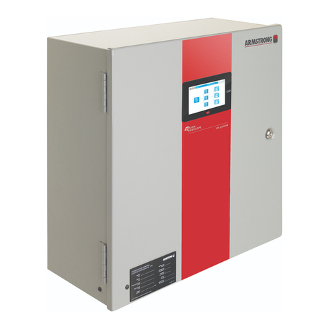
HID ACW2-XN User manual

Web-Based Access Control Solution
ACW2-XN
Installation Guide
ACW2XN-902-EN, Rev. A.2
PLT-03474 A.2
1 Introduction
Product Description
HID Global's
Web-based Access Control Solution for small businesses,
ACW2-XN
, provides a turnkey
solution for small facilities. Meet today’s security challenges and benefit from support for state-of-the-art
identity management and reliability of an enterprise level hardware at a fraction of the cost.
Reduce risk and response time for lost or stolen credentials. Use a standard web browser to access the
intuitive management portal. The web-based portal,
HID Access Manager
, makes it convenient to
provision and revoke smart cards without the expense or difficulties of managing physical keys.
In addition to access and identity management,
ACW2-XN
provides valuable built-in business tools. Basic
reporting and full audit logs are available at the touch of a button through the web-based portal.
Reliable and backed by a strong warranty, HID Global puts access control from a trusted industry leader
within reach.
ACW2-XN
can be expanded to support up to sixteen doors with additional AW2 Wiegand door modules.

Page 2 of 26 Installation Guide
© 2018 HID Global Corporation All rights reserved.
Web-Based Access Control Solution
ACW2-XN
2 System Specifications
Hardware Capabilities
Feature
Specification
Max People 1000
Max Cards 3 Cards per Person
Max Logs 100 000 events
# of Doors 2 Doors or 1 APB Door
(*Expandable to 16 doors, or 8 APB Doors)
*Note:
1. Additional ACW2-XN and/or AW2 modules are required.
2. See System Architecture – Best Practices on page 4 for more details.
3 What’s in the Packaging
ACW2-XN Contents
ACW2-XN
Spare
Labels
Cable Ties &
Anchor
Metal-Oxide
Varistors
Spare
Fuse
Drilling
Template
Quick Install
Guide
More
Documentation
http://hid.gl/ac-doc

© 2018 HID Global Corporation All rights reserved.
Installation Guide Page 3 of 26
Web-Based Access Control Solution
ACW2-XN
4 Installation Preparation
System Requirements
•Compatible browser (See details on page 14)
•Access to a mains power outlet.
•Access to an Ethernet Network point or a router/switch that will allow network connectivity.
•In the absence of any network, HID Access Manager can be set up and administered by
connecting a desktop/laptop PC directly to the Controller Module with an (uncrossed) network
cable.
Suggested Tools
•Electric drill
•Drill bits (Masonry / steel – to suite the site wall materials)
•Screwdriver, small, flat
•Wire strippers
•Side cutters
•Site plan (to lay out door and reader locations)
Additional Hardware
•Electric strike locks and/or mag locks
•Power supply with sufficient capacity to power the locks (see calculations on page 19)
•Push buttons for Request-to-Exit (REX)
•Door Position Sensor (DPS) switches (if not built into the locks)
•Mains power cable with a plug on one end
•Cable for Wiegand Readers, sufficient for the site (measure the site)
•Cable for Door Position Sensor and Request-to-Exit, sufficient for the site (measure the site)

Page 4 of 26 Installation Guide
© 2018 HID Global Corporation All rights reserved.
Web-Based Access Control Solution
ACW2-XN
5 System Architecture – Best Practices
One or two ACW2-XN enclosures?
ONE ACW2-XN enclosure
•is sufficient for up to 8 readers
•AND if all doors are within reasonable cabling distance of the enclosure
TWO ACW2-XN enclosures are needed
•for 9 to 16 readers
•OR if a second group of doors is a significant distance away from the first group. The two
enclosures are linked with an RS-485 cable, saving on long, multiple-reader cable runs.
(Remember that the total door count still cannot exceed the 16-door limit.)
How many AW2 Modules are needed?
•One
AW2
Module is needed for each door that has both entry and exit readers.
•One
AW2
Module is needed for every TWO doors that only require entry readers
NOTE:
•Any combination of single-readers and two-reader doors is permissible
•Readers may be independently allocated to any door
•Whatever the combination, no more than sixteen doors are supported
Example using three AW2 Wiegand Modules:
Any combination of single-reader or entry+exit-reader doors is possible

© 2018 HID Global Corporation All rights reserved.
Installation Guide Page 5 of 26
Web-Based Access Control Solution
ACW2-XN
16 Reader (8 APB Door) Example
Note:
•HID Access Manager will only accommodate 16 doors in total.
Master and Slave Controlling eight anti pass-back doors

Page 6 of 26 Installation Guide
© 2018 HID Global Corporation All rights reserved.
Web-Based Access Control Solution
ACW2-XN
6 Mounting the ACW2-XN
Mounting Location Considerations
Shelter and Security
Single ACW2-XN cable run considerations
Second/Slave ACW2-XN cable run considerations
NOTE that the Slave ACW2-XN:
•Does NOT connect to the network
•MUST connect via RS-485 to the Master ACW2-XN
•Is able to continue reading cards and controlling its doors in the event of an RS-485 cable break
AC Mains Outlet
RS-485 from Master ACW2-XN
(Up to 1 000 m)
Secure indoor location
Away from the weather
AC Mains Outlet
Network
Choose mounting location to
minimise door cabling runs
Choose mounting location to
minimise door cabling runs
< 150 m, 492 ft. Cable
< 150 m, 492 ft. Cable

© 2018 HID Global Corporation All rights reserved.
Installation Guide Page 7 of 26
Web-Based Access Control Solution
ACW2-XN
Removal/Fitting the Lid
Mark Up Mounting Holes Using Drilling Template
1. Select fasteners that are appropriate for the mounting surface (masonry/wood/ dry wall)
2. Select the drill size appropriate for the fasteners
3. Fix the Drilling Template against the chosen vertical surface (using the supplied double-sided tape),
making sure that the top edge is horizontal. (Remember to allow 30 mm clearance on the left of the
ACW2-XN enclosure to allow the door to hinge fully open.)
4. Centre punch the two mounting hole locations
5. Drill holes of a diameter that is suitable for the fasteners
6. Remove the lid from the enclosure (as per instructions above)
7. Mount the enclosure to the surface
8. Replace the lid (and plug the lid cable back in) after the system wiring is complete
9. Place the AC and AW2 module labels in the correct positions provided on the back page of the
ACW2-XN Quick Install Guide. The information on the labels will be used during the door
configuration process via HID Access Manager.
Expanding the controller with more Wiegand Modules
The
ACW2-XN
comes assembled with one AW2 module, and can support another three AW2 modules.
Additional AW2 modules are plugged into the sides of the existing modules, and then fastened in place
with the four mounting screws that are included with each AW2 module.
Remember to place the additional AW2 Module labels on the back page of the ACW2-XN Quick Install
Guide
Note:
•
AW2
modules may be added or removed without powering down the system.
1. 2. 3.
Open the lid &
unplug the cable
Remove the lid
Slide the lid upward

Page 8 of 26 Installation Guide
© 2018 HID Global Corporation All rights reserved.
Web-Based Access Control Solution
ACW2-XN
7 Wiring the System
AW2 Wiegand Module
AW2 Module Cable Specifications
Application Conductors
(# of Wires) Cross Sectional Area AWG Max Cable Length
Door Strike (12V and higher) 2 0.75 mm2, 0,0012 in218 150 m, 492 ft.
Card Reader 10 (8 used) 0.32 mm
2
, 0.0005 in
2
20 150 m, 492 ft.
Door Contact 2 0.32 mm
2
, 0.0005 in
2
20 150 m, 492 ft.
Request-to-Exit 4 0.32 mm
2
, 0.0005 in
2
20 150 m, 492 ft.
MOV (included in the packaging) Specification
MOV Rating 25VRMS 500A 77VMax Clamping
Where to use the suppled MOVs
The MOVs MUST be connected across 12V inductive loads to prevent sparking at the
relay contacts.
The supplied MOVs are only for 12V applications, and are MANDATORY
Supervised Inputs (Optional)
HID Access Manager can monitor the Door Position Sensor (DPS) circuits for tampering
when resisters are installed.
Two 1kΩresistors are required for every sense line. These should be installed in a
location where they cannot be accessed without opening the door in question:
This feature must be activated in HID Access Manager via the door configuration
process.
0V
+12V
COM
NC

© 2018 HID Global Corporation All rights reserved.
Installation Guide Page 9 of 26
Web-Based Access Control Solution
ACW2-XN
AW2 Key Components Diagram
* AW2 Wiegand Modules have spare Earthing Terminals – see page 12 for details
DIP-switch Position Function
1110
(Factory Set DIP Switch Position)
Wiegand 26-bit, 44-bit, 40-bit, 37-bit and card + PIN-code Mode.
Module Data LED
Relay 1 Terminals
Relay 2 Terminals
Wiegand
Reader
1
Terminals
Door Position Sensor 1
Request-to-Exit 1
Wiegand
Reader
2
Terminals
Relay Status LEDs
Input Status LEDs
Door Position Sensor 2
Request-to-Exit 2
0V
0V
Module Power
Status LED
DIP Switch 1
DIP Switch 2
*Earthing Terminal
(ETH)

Page 10 of 26 Installation Guide
© 2018 HID Global Corporation All rights reserved.
Web-Based Access Control Solution
ACW2-XN
AW2 Wiring Example
*DPS: Some electric strike locks include Door Position Sense terminals. When they don’t, additional
sensors should be fitted if door position sensing is required.
Some strike locks and maglocks have built-in arc suppression. Consult the installation information for the
locks you are using. It is recommended that the MOVs (supplied with the Wiegand Module) are
connected across any inductive loads.
NB: The supplied MOVs are only suitable for 12V applications.
CAUTION:
•Inadequate spark suppression can result in early failure of relay contacts – and will void the
warranty on the affected AW2 module.
NC
COM
+12V
COM
NO
0V
*DPS
REX – Door #2
REX – Door #1
DPS – Door #1
Maglock – Door #1
Strike Lock – Door #2
12V DC
PSU
Wiegand Reader #1
Colour
Function
Red
12V
Black
0V
Green
D0
White
D1
Brown
RED
Orange
GREEN
Yellow
Buzzer
Blue
Hold
Grey
Shield
Wiegand Reader #2
Function
Colour
Shield
Grey
Hold
Blue
Buzzer
Yellow
GREEN
Orange
RED
Brown
D1
White
D0
Green
0V
Black
12V
Red
Terminal blocks unplug, giving easy
access to the terminal screw heads

© 2018 HID Global Corporation All rights reserved.
Installation Guide Page 11 of 26
Web-Based Access Control Solution
ACW2-XN
Controller Module
Cable Specifications
Application Conductors Cross Section Max Cable
Length
Network 8 >= 0,75 mm
2
150 m
RS-485 Twisted pair, with or without screen >= 0.51 mm
2
1 000 m
Key Components and Connections
Note:
•Any module that has changes made to its DIP Switch settings while already powered up must be
powered down and powered up again. This is because the settings are only read by the module
during the power up cycle.
DIP-switch Position Function MODE
0000
Slave Controller Mode
0100
Master Controller Mode
RJ45 Network Socket
12 VDC Supply
(Pre-Wired)
Device RS-485 Terminal
This is used for linking
the Master Controller to
the Slave Controller
Enclosure Anti-Tamper
(Pre-Wired)
DIP Switches
Factory set for
Master (0100)
Host RS-485 Terminal
Reserved for future expansion
Battery Tag
REMOVE before
powering up the system
Earthing Terminal
(See page 12 for details)

Page 12 of 26 Installation Guide
© 2018 HID Global Corporation All rights reserved.
Web-Based Access Control Solution
ACW2-XN
DIP-switch Position Function MODE
1XXX
*Special Function – See notes on the next
page
Factory Default Mode
Set DIP Switch 1 to
ON
, cycle power to the
Module, wait for Controller restart (~20
seconds), and return DIP Switch 1 to
OFF.
(Switches 2, & 4 don’t matter)
Note:
•
FACTORY DEFAULT IS AN ABSOLUTE LAST RESORT
Defaulting the Controller Module will erase all HID Access Manager data, including any static IP
address that was set up – so this address should be noted somewhere safe for future use.
•The most likely reason for choosing to default a Control Module would be when the HID Access
Manager IP address is accidentally set outside of the mask, and HID Access Manager becomes
inaccessible.
•As long as the IP subnet of the Controller Module is the same as the PC/Laptop, the
Device
Discovery Tool
may be used to discover the address and allow you to login and set up an
appropriate IP address. The
Device Discovery Tool
is available for download from the “More
Documentation” link included on page 2.
Earthing Terminal
The Controller and Wiegand Modules are sensitive to Electrostatic Discharges (ESD). Observe
precautions while handling the circuit board assemblies by using proper grounding straps and handling
precautions at all times.
To furher protect against the harmful effects of EMC and transients, a functional earth connection point is
provided as a screw terminal (see silkscreen marking: ETH).
SYSTEM BACKUP
Always
back up the system data using the
Access Manager Utility Tool
. This could save you having to
set up the system from scratch again in the event of a system default, as described above. The
Access
Manager Utility Tool
is available for download from the “More Documentation” link included on page 2.
Connecting two ACW2-XN units via RS-485
Link the two Controller Modules by connecting their RS-485 Device terminals. Remember to set the DIP
Switches on the second Controller Module (in the remote ACW2-XN) to SLAVE (0000) – and remember
to cycle the power to the module in question if you have changed the DIP Switch Settings while it is
already in the powered up state.
Note:
•The Slave ACW2-XN is NOT connected to the Network
•The total door count (Slave + Master) may not exceed 16 doors

© 2018 HID Global Corporation All rights reserved.
Installation Guide Page 13 of 26
Web-Based Access Control Solution
ACW2-XN
Mains supply connection
Mains Cable Specification
•Use a mains plug that is standard for the region.
•Select cable that is in accordance to National Wiring code best practices of your local authority.
Mains Cable connection
1. Lay the mains cable from the mains outlet to the IPS enclosure, ensuring that in is
NOT
plugged in to
the mains outlet.
2. Pass the mains cable through a gland in the enclosure wall and follow the route indicated by the
yellow arrow. (It should pass behind the battery, if it were installed)
3. Strip the ends mains cable, exposing 10 mm of the conductors.
4. Press down on the terminal buttons while threading each stripped wire end into its corresponding
terminal.
5. Releasing the terminal button will clamp the stripped wire end in place.
6. Take some time to thoroughly inspect all the wiring and correct any mistakes before progressing to
the next step.
7. Pull out the plastic tag from under the Lithium Button Cell on the Controller Module’s PCB.
8. Plug the mains supply cable into the outlet socket and power up the installation.
9. The STAT (Status) LEDs on the Controller and Wiegand Modules will flash rapidly for approximately
one second.
10. After one second the Controller STAT LED will turn off during the booting process. The Wiegand
Modules’ STAT LEDs will remain on constantly as long as a suitable supply voltage is present.
11. Once satisfied that here are no short circuits it is now safe to connect the recommended 12V battery
(not included) using the ACW2-XN’s integrated spade terminal plugs.
Power Supply
Battery Cables
Lid Earth
Cable Plug
Mains Cable
Route
Mains Terminal Block

Page 14 of 26 Installation Guide
© 2018 HID Global Corporation All rights reserved.
Web-Based Access Control Solution
ACW2-XN
8 Network Setup
Compatibility
Before commencing network setup, be sure that operating system and browser are supported. At
time of writing , HID Access Manager compatibility includes the following full releases (or later):
•Firefox 52.0.2
•Chrome 58.0.3029.110
•IPhone 6 (version 10.1.1)
•Android 6
•Windows 7
DNS Name function
•The DNS Name function only works with a PC
If you wish to use DNS feature with mobile phones then you need to set the DNS setting within your
WLAN router.
(Note that the DNS setting is router-manufacturer dependent, and not all routers support this.)
First steps:
1. If you have not done so already, remove the plastic tag from under the button cell on the Controller
PCB.
2. Power up the
ACW2-XN
. (Allow a minute for it to boot up)
Note:
•Only one instance of the web interface may be opened at a time. Multiple Client connections are
not supported

© 2018 HID Global Corporation All rights reserved.
Installation Guide Page 15 of 26
Web-Based Access Control Solution
ACW2-XN
How to connect to HID Access Manager for the first time
First option: You have a Router with an active DHCP server
1. Follow this link: http://HIDaccess/ - or type it into the browser.
2. The HID Access Manager login dialogue will launch.
3. See Logging on, on the next page.
Second option: Switch or Direct connection
•Connect a PC/Laptop directly to the
ACW2-XN
network socket using a straight (uncrossed)
Ethernet cable – or via a network switch.
•The PC needs to have an IP address in the same range as the
ACW2-XN’s
default address.
1. Click Start>Control Panel.
2. Click the “Network and Sharing Centre icon”.
3. Select “Local Area Connection”.
4. Click the “Properties button”.
5. Double-click “Internet Protocol Version 4 (TCP/IPv4)”.
6. Set the IP Address to 192.168.100.X (X being any available number between 2 and 254. Ensure that
your chosen number is not the same as the
ACW2-XN
.
7. Set the Subnet Mask to 255.255.255.0.
8. Click the OK button.
9. Follow this link: 192.168.100.1 (or type it into the browser)
10. The HID Access Manager login dialogue will launch.
Note:
•It is advised to set up a static IP address for future use.
•The DNS name function only works on a PC
If you wish to use DNS features with Mobile phones then you need to set the DNS setting within your
router.
(DNS setting is router manufacturer dependent.)
Logging on
1. Enter the default Admin Password: 12345
2. Click Logon

Page 16 of 26 Installation Guide
© 2018 HID Global Corporation All rights reserved.
Web-Based Access Control Solution
ACW2-XN
… HID Access Manager will open on the “Live!” Screen:
Required Settings
Using the menu-driven interface (paths shown on the next page) complete these steps:
1. Set the date and time
2. Update the master password
3. Add/Configure doors and readers using the labels and door names on the back page of the ACW2-
XN Quick Install Guide.
4. Add/Manage people

© 2018 HID Global Corporation All rights reserved.
Installation Guide Page 17 of 26
Web-Based Access Control Solution
ACW2-XN
Function Paths
The menu headings are displayed in the menu ribbon – these give you access to the functions:
Live!
•Displays transactions in real time, latest on top
People
•Add people and manage their access accounts and their cards
Doors
•Click on
Device Discovery
to search for connected modules
•Add Door
•Reset APB
Reports
•Access Report
•Status Report
•Audit Report
•Hours Worked Report
Settings
•Network Settings
•Date and Time
•Security (Changing the password)
•Special Days (Add public holidays, etc.)
•Language (Change language preference - Preferencia cambiar idioma)
•Advanced options:
oAccess Groups
oUDP output (Destination Address setup)
oAPB Settings
oWiegand Settings
About
•Controller Module Firmware Version
•Web Application Version
System Overides
These buttons are always available on screen as long as long as you are logged in.
Button
Function
All controlled doors are UNLOCKED, allowing everybody to pass.
All controlled doors are LOCKED – and no cards will open doors.
Emergency Unlock
OR
Lockdown
will remain active until it is disabled by clicking on “Revert to
Normal State” – on the right hand end of the thick red stripe:
Button

Page 18 of 26 Installation Guide
© 2018 HID Global Corporation All rights reserved.
Web-Based Access Control Solution
ACW2-XN
9 Electrical Specifications
Power Supply (A-X1)
AC Mains Input
DC Output
100-230 VAC (50/60Hz), 1.3A 12V, 5A
Optional Battery (Strongly recommended)
Not included with the ACW2-XN, this battery must be sourced separately
Note:
•Only connect the battery after all system wiring is complete and tested on the built-in power
supply
Battery Specification
Type Lead Gel
Voltage 12V
Capacity 7 Ah
Physical Dimensions 65 mm x 101 mm x 151 mm,
2.56” x 3.98” x 5.95” – or smaller
Battery Protection
Fuse
Specification
Length 20 mm, 0.787”
Type Slow-blow
Rating 6.3 A
Controller Module (AC)
Power
Conditions Current Power
Supply at 12V DC 140 mA 1.7 W
Inter-Module Communications
Connector Purpose
10-way connectors:
female on the left,
male on the right
Power and data lines to other
modules
Network
Connector Protocol
RJ45
Ethernet, 10/100 Base T, half or full
duplex

© 2018 HID Global Corporation All rights reserved.
Installation Guide Page 19 of 26
Web-Based Access Control Solution
ACW2-XN
Controller module (AC1) continued…
RS-485 Ports (Device & Host)
Interface
Baud Rate
Data Format
RS-485 38 400 8 data bits, no parity, 1 stop bit
Wiegand Module (AW2)
Power (At 12V)
Conditions
Current
Power
Relays idle, No readers Connected 37 mA 0.44 W
Both relays activated, maximum reader load 503 mA 6 W
Relays
Contact
Rating
Configuration Contacts Operations
[10A, 28VDC]
[5A, 220VAC]
[12A, 120VAC]
Double Pole
Single Throw NO, NC, COM > 100 000 (with MOVs installed across
12V inductive loads – see page 8)
Inter-Module Communications
Connector Purpose
10-way connectors:
Female on the left, male on the right
Power and data lines to other modules
Wiegand Reader Port
Connector Reader Connections
10-way Screw Terminal Plugs
12V, 5V, 0V, D0, D1, LED (Red), LED (Green), Buzzer, Hold,
Shield
Battery Charging Circuit
Conditions Current Power
Supply at 12V DC, battery flat, max charge current 500 mA 6 W
Calculations
The following calculation must be performed for each additional DC power Supply, together with all locks
that are powered from that power supply.
*
Note:
See individual lock and power supply installation manuals for current consumption and maximum
current output.
12 V Power Supply max current
output
-
Maximum lock current total
Margin
(The margin may not be negative.)

Page 20 of 26 Installation Guide
© 2018 HID Global Corporation All rights reserved.
Web-Based Access Control Solution
ACW2-XN
10 FAQ
Fail Safe versus Fail Secure
Electrically controlled locks fall in to one of two categories:
1. Locks that require power to lock (with loss of power, these are unlocked, allowing EVERYBODY
access)
2. Locks that require power to unlock (with loss of power, these are locked, allowing NOBODY
access)
The first is considered fail SAFE, as people can still escape the building, and help can get in, should some
misfortune occur.
The second is considered fail SECURE, as intruders cannot just walk in when power is lost.
Which lock to use
Mag locks are inherently Fail Safe, as they require power to lock.
Strike locks are available in Fail Safe as well as Fail Secure versions, but are most often Fail Secure.
CAUTION:
•There is another level that should also be considered:
What relay terminals to use
The relays on the AW2 module should be switching power from an independent source, and so a similar
principle also applies to your choice of Normally Open (NO) or Normally Closed (NC) relay terminals:
Use the NC and COM terminals for switching circuits that you wish to keep energised should power to the
AW2 module be lost.
Use the NO and COM terminals for switching circuits that you wish to be cut off in the event that power
to the AW2 module is lost.
Other manuals for ACW2-XN
2
Table of contents
Other HID Controllers manuals

HID
HID VertX EVO V2000 User manual
HID
HID Signo 25B User manual
HID
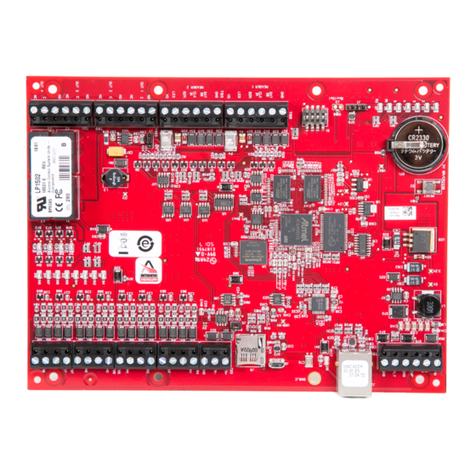
HID Mercury LP1502 User manual
HID
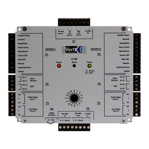
HID VertX EVO Series User manual
HID
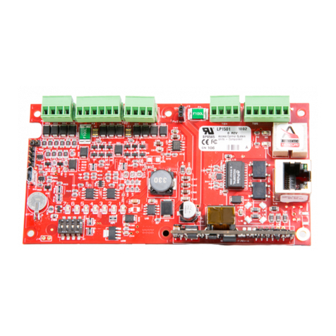
HID Mercury LP1501 User manual
HID
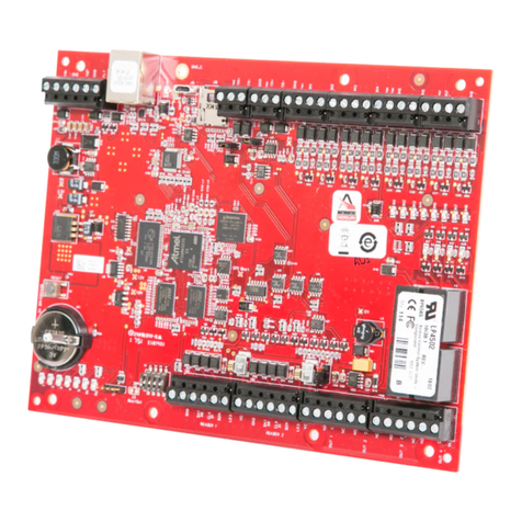
HID Mercury LP4502 User manual
HID
HID EDGE EVO EH400-K User manual
HID
HID iCLASS SE RB25F User manual
HID
HID Aero X1100 User manual
HID
HID Vertx CS V100 User manual
