HIdRos HMA/Z Series User manual

INDUSTRIAL DEHUMIDIFIERS WITH TEMPERATURE CONTROL
HMA/Z
SERIES
MTEC.6710.GB-D-1 Operation and maintenance manual HMA/Z series English Rev. D 02-2021
Multiple instructions:
&RQVXOWWKHVSHFL¿FSDUW
Read and understand
the instructions before
undertaking any work on
the unit
RETAIN FOR FUTURE REFERENCE
Incorporated in this document are the following:
• Declaration of conformity
• Technical manual
• Dimensional drawing
TECHNICAL MANUAL
Original instructions

Rev. D 02-2021
2
MTEC.6710.GB-D-1 Operation and maintenance manual HMA/Z series English
HMA/Z,QGXVWULDOGHKXPLGL¿HUVZLWKWHPSHUDWXUHFRQWURO
Declaration of conformity
We declare under our own responsibility that the below equipment complies in all parts with the CEE and EN directives.
The declaration of conformity is enclosed to the technical booklet enclosed with the unit.
7KHXQLWFRQWDLQVÀXRULQDWHGJUHHQKRXVHJDVHV
Reproduction, data storage and transmission, even partial, of this publication, in any form, without the prior written authorisation of the
Company, is prohibited. The Company can be contacted for all inquiries regarding the use of its products.
7KH &RPSDQ\ IROORZV D SROLF\RI FRQWLQXRXV SURGXFW GHYHORSPHQW DQG LPSURYHPHQWDQG UHVHUYHV WKH ULJKW WRPRGLI\ VSHFL¿FDWLRQV
equipment and instructions regarding use and maintenance at any time, without notice.

Rev. D 02-2021
3
5
5
5
5
5
5
6
7
8
8
9
10
10
10
11
11
11
11
12
12
13
14
18
19
19
20
20
20
20
21
21
21
21
22
22
23
24
25
26
27
27
28
29
30
31
31
32
33
33
34
35
37
37
39
39
MTEC.6710.GB-D-1 Operation and maintenance manual HMA/Z series English
HMA/Z,QGXVWULDOGHKXPLGL¿HUVwith temperature control
INDEX
1. INTRODUCTION.....................................................................................................................................................................................
1.1 Preliminary information......................................................................................................................................................
1.2 Aim and content of the manual ..........................................................................................................................................
1.3 How to store this manual ...................................................................................................................................................
1.4 Manual Update ..................................................................................................................................................................
1.5 How to use this manual .....................................................................................................................................................
1.6 Potential Risks...................................................................................................................................................................
1.7 General Description of Symbols Used...............................................................................................................................
1.8 Safety symbols used..........................................................................................................................................................
1.9 Limitations and prohibited use...........................................................................................................................................
8QLWLGHQWL¿FDWLRQ .............................................................................................................................................................
2. SAFETY .................................................................................................................................................................................................
2.1 Warning re potentially hazardous toxic substances...........................................................................................................
2.2 Refrigerant handling ..........................................................................................................................................................
2.3 Prevent inhalation of high vapor concentration..................................................................................................................
2.4 Procedures to be adopted in the event of accidental release of refrigerant ......................................................................
2.5 Main Toxicological Information Regarding the Type of refrigerant used ............................................................................
2.6 First Aid Measures.............................................................................................................................................................
3. TECHNICAL CHARACTERISTICS .........................................................................................................................................................
3.1 Unit description..................................................................................................................................................................
3.2 Accessories .......................................................................................................................................................................
3.3 Technical data....................................................................................................................................................................
3.4 Operation limits..................................................................................................................................................................
3.5 Sound data ........................................................................................................................................................................
3.6 Safety devices ...................................................................................................................................................................
4. INSTALLATION .......................................................................................................................................................................................
4.1 General safety guidelines and and use of symbols ...........................................................................................................
4.2 Health and safety Considerations .....................................................................................................................................
4.3 Personal protective equipment .........................................................................................................................................
4.4 Inspection .........................................................................................................................................................................
4.5 Storage ..............................................................................................................................................................................
4.6 Unpacking..........................................................................................................................................................................
4.7 Lifting and handling............................................................................................................................................................
4.8 Location and minimum technical clearances.....................................................................................................................
4.9 Condensate draining connections .....................................................................................................................................
+RZWRUHPRYH¿OWHUV.......................................................................................................................................................
4.11 Refrigerant connections for Z version ..............................................................................................................................
4.12 Refrigerant diameters lines for version Z.........................................................................................................................
4.13 Refrigerant schema .........................................................................................................................................................
4.14 Installation of built-in room electronic sensor (RGDD).....................................................................................................
4.15 Serial interface card RS485 (INSE).................................................................................................................................
4.16 Connecting the unit to air duct channels..........................................................................................................................
4.17 Fan positioning ................................................................................................................................................................
4.18 Electric connections: preliminary safety information........................................................................................................
4.19 Electrical data ..................................................................................................................................................................
4.20
How to connect the power supply....................................................................................................................................
4.21 Electric connections.........................................................................................................................................................
5. UNIT START UP......................................................................................................................................................................................
5.1 Preliminary checks.............................................................................................................................................................
5.2 Description of the control panel .........................................................................................................................................
5.3 Remote control panel.........................................................................................................................................................
6. USE .........................................................................................................................................................................................................
6.1 Switch the unit on ..............................................................................................................................................................
6.2 Stop ...................................................................................................................................................................................
6.3 Stand-by ............................................................................................................................................................................

Rev. D 02-2021
4
39
40
40
40
41
41
42
42
42
44
45
45
45
45
46
46
47
MTEC.6710.GB-D-1 Operation and maintenance manual HMA/Z series English
HMA/Z,QGXVWULDOGHKXPLGL¿HUVZLWKWHPSHUDWXUHFRQWURO
6.4 How to change the set points ............................................................................................................................................
6.5 Acoustic signal silencing....................................................................................................................................................
6.6 Display during alarm..........................................................................................................................................................
6.7 Alarm reset.........................................................................................................................................................................
7. MAINTENANCE OF THE UNIT...............................................................................................................................................................
7.1 General warnings...............................................................................................................................................................
7.2 Drive access ......................................................................................................................................................................
7.3 Scheduled maintenance ....................................................................................................................................................
7.4 Periodical checks...............................................................................................................................................................
7.5 Refrigerant circuit repair ....................................................................................................................................................
8. DECOMMISSIONING.............................................................................................................................................................................
8.1 Disconnect the unit ............................................................................................................................................................
8.2 Disposal, recovery and recycling.......................................................................................................................................
8.3 RAEE Directive (only UE)..................................................................................................................................................
9. DIAGNOSIS AND TROUBLESHOOTING..............................................................................................................................................
)DXOW¿QGLQJ ......................................................................................................................................................................
10.DIMENSIONAL DRAWINGS ..................................................................................................................................................................

Rev. D 02-2021
5
MTEC.6710.GB-D-1 Operation and maintenance manual HMA/Z series English
HMA/Z,QGXVWULDOGHKXPLGL¿HUVwith temperature control
1. INTRODUCTION
1.1 Preliminary information
1.2 Aim and content of the manual
1.3 How to store this manual
1.4 Manual Update
1.5 How to use this manual
Reproduction, storage or transmission of any part of this publication in any form, without the prior written consent of the Company, is pro-
hibited.
The unit to which these instructions refer, is designed to be used for the the purposes described and to be operated in accordance with
these instructions.
The Company will not be liable for claims for damage caused to persons, animals, material goods or property caused by improper installa-
WLRQDGMXVWPHQWDQGPDLQWHQDQFHRULPSURSHUXVH$Q\XVHQRWVSHFL¿HGLQWKLVPDQXDOLVSURKLELWHG
This document is intended to provide information only and does not form a contract with third parties.
The Company pursues a policy of constant improvement and development of its products and therefore reserves the right to change the
VSHFL¿FDWLRQVDQGWKHGRFXPHQWDWLRQDWDQ\WLPHZLWKRXWQRWLFHDQGZLWKRXWREOLJDWLRQWRXSGDWHH[LVWLQJHTXLSPHQW
These instructions are intended to provide the information required for the selection, installation, use and maintenance of the unit.
They have been prepared in accordance with the European Union laws and with the technical standards in force at the date of issue of the
instructions.
The instructions contain all the necessary information to prevent any reasonably foreseeable misuse.
The manual must be kept in a suitable place with easy access for users and operators, protected from dust and damp.
The manual must always accompany the unit during the entire life cycle of the same and therefore must be transferred to any subsequent
user.
It is recommended that the manual is updated to the latest revision available.
If updates are sent to the customer they must be added to this manual.
The latest information regarding the use of its products is available by contacting the Company.
The manual is an integral part of the unit.
Users or operators must consult the manual before performing any operation and especially so when transporting, han-
dling, installating, maintaining, or dismantling the unit in order to eliminate uncertainty and reduce risk.
In these instructions symbols have been used (described in the following paragraphs) to draw the attention of operators
and users to the operations that have a higher risk and which must be performed safely.

Rev. D 02-2021
6
MTEC.6710.GB-D-1 Operation and maintenance manual HMA/Z series English
HMA/Z,QGXVWULDOGHKXPLGL¿HUVZLWKWHPSHUDWXUHFRQWURO
1.6 Potential Risks
Whilst the unit has been designed to minimize any risk posed to the safety of people who will interact with it, it has not been technically
possible to eliminate completely the causes of risk. It is therefore necessary to refer to the requirements and symbolism below:
LOCATION OF
RISK
POTENTIAL
RISK METHOD OF INJURY PRECAUTIONS
Thermal heat
exchangers. Small stab wounds. Contact Avoid any contact,
use protective gloves.
Fan and fan grilles. Cuts, eye damage,
broken bones.
Insertion of sharp objects
through the grid while the
fans are operating.
Never put objects through the protection grilles.
Internal component:
compressors and
discharge pipes
Burns. Contact Avoid any contact, use protective gloves.
Internal component:
electric cables and
metallic parts
Electrocution,
severe burns.
Defect in the supply ca-
ble insulation, live metal-
lic parts.
Adequate protection of power cables, ensure
correct earthing of all metal parts.
External to unit:
unit enclosure
Poisoning,
severe burns.
Fire due to short circuit
or overheating of the
supply cable external to
unit.
Size cables and mains protection system in ac-
cordance with iee regulations.
Low pressure safety
valve.
Poisoning,
severe burns.
High evaporating pres-
sure causing a refgrig-
erant discharge during
maintenance.
Carefully check the evaporating pressure dur-
ing the maintenance operations. Use all personal
protective equipment required by the law. PPE
must also protect against gas leaks from the
safety valve. The outlet of these valves is di-
rected to avoid causing damage to persons or
goods.
High pressure safety
valve.
Poisoning,
severe burns,
hearing loss.
Activation of the high
pressure safety valve
with the refrigerant circuit
open.
If possible, do not open the refrigerant circuit
valve; carefuly check the condensing pressure;
use all the personal protective equipment re-
quired by law. PPE must also protect against gas
leaks from the safety valve. The outlet of these
valves is directed to avoid causing damage to
persons or goods.
Entire unit ([WHUQDO¿UH
Fire due to natural dis-
asters or combustions of
elements nearby unit
3URYLGHWKHQHFHVVDU\¿UH¿JKWLQJHTXLSPHQW
Entire unit
Explosion, injuries,
burns, poisoning,
folgoramento for natural
disasters or earthquake.
Breakages, failures due
to natural disasters or
earthquake
Plan the necessary precautions both electrical
(suitable differential magneto and electrical pro-
tection of the supply lines; greatest care during the
connections of the metal parts), and mechanical
(special anchors or seismic vibrations to prevent
breakages or accidental falls ).

Rev. D 02-2021
7
MTEC.6710.GB-D-1 Operation and maintenance manual HMA/Z series English
HMA/Z,QGXVWULDOGHKXPLGL¿HUVwith temperature control
BANNED
A black symbol inside a red circle with a red diagonal indicates an action that should not be performed.
WARNING
A black graphic symbol added to a yellow triangle with black edges indicates danger.
ACTION REQUIRED
A white symbol inserted in a blue circle indicates an action that must be done to avoid a risk.
7KHJUDSKLFV\PERO³ZDUQLQJ´LVTXDOL¿HGZLWKDGGLWLRQDOVDIHW\LQIRUPDWLRQWH[WRURWKHUV\PEROV
Safety symbols combined in accordance with ISO 3864-2:
1.7 General Description of Symbols Used
Safety symbols combined in accordance with ISO 3864-2:
Rev. D 02-2021
8
MTEC.6710.GB-D-1 Operation and maintenance manual HMA/Z series English
HMA/Z,QGXVWULDOGHKXPLGL¿HUVZLWKWHPSHUDWXUHFRQWURO
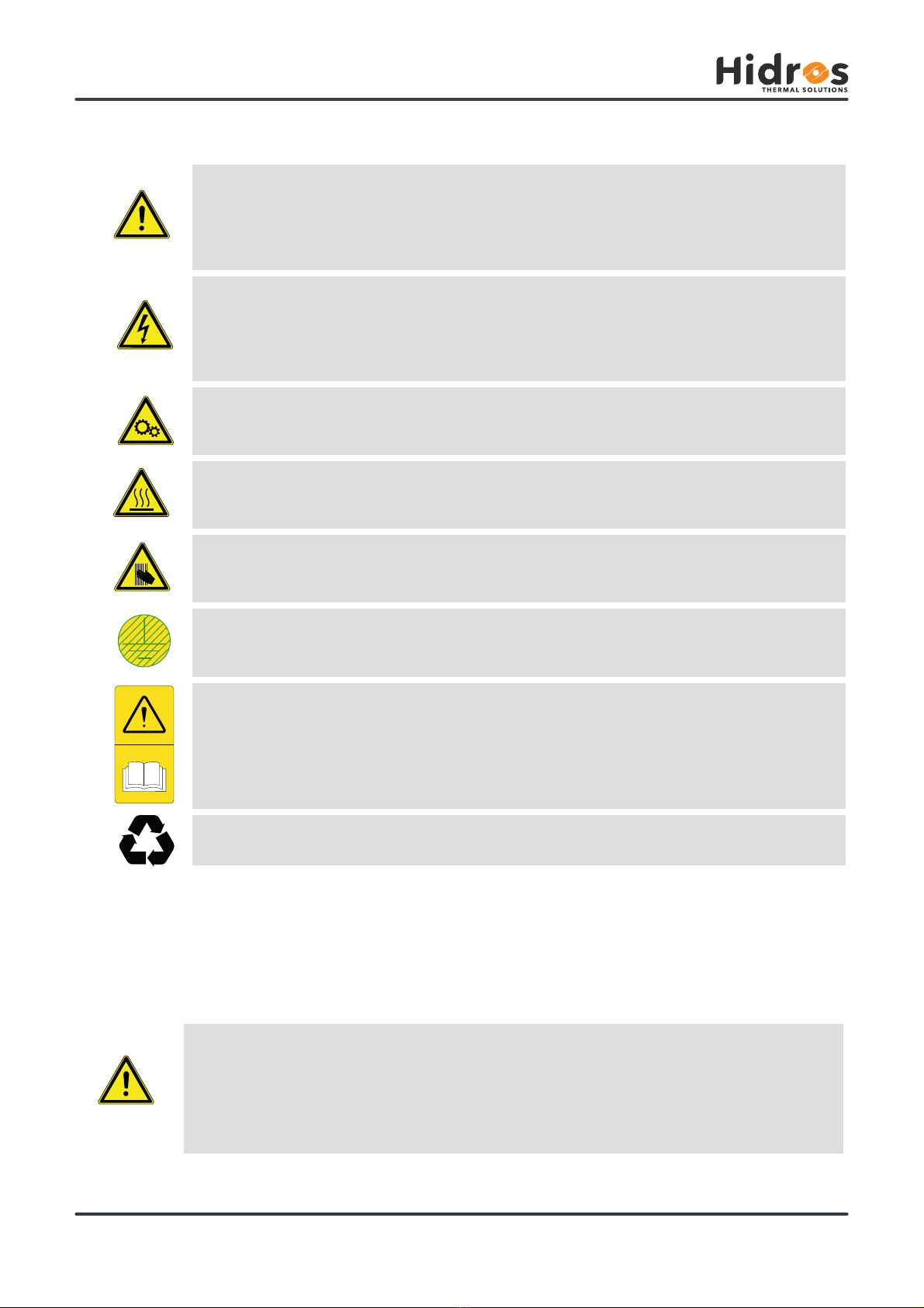
GENERAL RISK
Observe all signs placed next to the pictogram. The failure to follow directions may create a risk situation that may
be injurious to the user.
ELECTRICAL HAZARD
Observe all signs placed next to the pictogram.
The symbol indicates components of the unit and actions described in this manual that could create an electrical
hazard.
MOVING PARTS
The symbol indicates those moving parts of the unit that could create risk.
HOT SURFACES
The symbol indicates those components with high surface temperature that could create risks.
SHARP SURFACES
The symbol indicates components or parts that could cause stab wounds.
EARTH CONNECTION
7KHV\PEROLGHQWL¿HV(DUWKLQJFRQQHFWLRQSRLQWVLQWKHXQLW
READ AND UNDERSTAND THE INSTRUCTIONS
Read and understand the instructions of the machine before any operations.
RECOVER OR RECYCLE MATERIAL
1.8 Safety symbols used
The unit is not suitable for operations in environments:
• excessively dusty or potentially explosive atmospheres;
• where there are vibrations;
ZKHUHWKHUHDUHHOHFWURPDJQHWLF¿HOGV
• where there are aggressive atmospheres
The machine is designed and built exclusively for the uses described in “Limitations of use” of the technical manual.
Any other use is prohibited because it may pose a potential risk to the health of operators and users.
1.9 Limitations and prohibited use

Rev. D 02-2021
9
Manufacturer: PD322111
Contiene gas fluorurati ad effetto serra disciplinati dal protocollo di Kyoto
Contains fluorinated greenhouse gasses covered by the Kyoto protocol
Modello
Model
1HMA.750S-2A 123456
2 8/2017
R410A
8 Kg 16,7 ton
2 2088
400V-3ph-50Hz
22 bar 42 bar
-30 °C
420 Kg
+130 °C -30 °C +130 °C
37,50 A 21,70 kW
Matricola
Serial number
Categoria PED
PED Category
Tipo refrigerante
Refrigerant type
Tensione-Fasi-Frequenza
Voltage-Phases-Frequency
LATO BASSA PRESSIONE
LOW PRESSURE SIDE
LATO ALTA PRESSIONE
HIGH PRESSURE SIDE
Gruppo fluido
Fluid group GWP
Carica refrigerante
Refrigerant charge
C1
C3
C2
Min Max Min Max
C4
F.L.A. (A) F.L.I. (kW)
PS
Temperatura di progetto
Design temperature
Peso a vuoto
Weight
Temperatura di progetto
Design temperature
CO2Equivalente
CO2Equivalente
Data di fabbricazione
Manifacture date
PS
FAC SIMI
C
FAC
AC
SI
SI
MILE
LE
LE
E
MI
F
16,7 ton
22 bar
37,
enza
uency
SA PRESSIONE
ESSURE SID
Equivalente
F
CO
2
Equivalen
F
Via E. Mattei, 20
35028 Piove di Sacco PD - Italy
+39 049 9731022
www.hidros.eu
MTEC.6710.GB-D-1 Operation and maintenance manual HMA/Z series English
HMA/Z,QGXVWULDOGHKXPLGL¿HUVwith temperature control
The product label should never be removed from the unit.
8QLWLGHQWLÀFDWLRQ
Each unit has a rating plate that provides key information regarding the machine.
The rating plate may differ from the one shown below as the example is for a standard unit without accessories.
For all electrical information not provided on the label, refer to the wiring diagram.
An image of the label is shown below:

Rev. D 02-2021
10
MTEC.6710.GB-D-1 Operation and maintenance manual HMA/Z series English
HMA/Z,QGXVWULDOGHKXPLGL¿HUVZLWKWHPSHUDWXUHFRQWURO
,GHQWLÀFDWLRQRIWKH7\SHRI5HIULJHUDQW)OXLG8VHG5$
'LÀXRURPHWKDQH+)&E\ZHLJKW&$61R
3HQWDÀXRURHWKDQH+)&E\ZHLJKW&$61R
2.1.6 Permissible exposure limit
R410A
HFC-32 TWA 1000 ppm
HFC-125 TWA 1000 ppm
:DUQLQJUHSRWHQWLDOO\KD]DUGRXVWR[LFVXEVWDQFHV
2. SAFETY
For further information regarding the characteristics of the refrigerant and oil used, refer to the safety data sheets
available from the refrigerant and oil manufacturers.
,GHQWLÀFDWLRQRIWKH7\SHRI2LO8VHG
The lubricant used is polyester oil. Please refer to the information provided on the compressor data plate.
(19,5210(17$/3527(&7,21Read the ecological information and the following instructions carefully.
Main Ecological Information Regarding the Types of refrigerants Fluids used.
3HUVLVWHQFHDQGGHJUDGDWLRQ
(IIHFWVRIGLVFKDUJHV
2.1.5 Exposure controls and personal protection
The refrigerants used decompose in the lower atmosphere (troposphere) relatively quickly. The decomposed products are highly dispers-
LEOHDQGWKHUHIRUHKDYHDYHU\ORZFRQFHQWUDWLRQ7KH\GRQRWLQÀXHQFHWKHSKRWRFKHPLFDOVPRJZKLFKLVQRWDPRQJWKH92&YRODWLOH
organic compounds (as stipulated in the guidelines to the UNECE). The constituent refrigerants of R410A (R32 and R125), do not damage
the ozone layer. These substances are regulated under the Montreal Protocol (revised 1992) and regulations EC no. 2037/200 of 29 June
2000.
Discharges into the atmosphere of this product does not cause a long-term contamination.
Wear protective clothing and gloves, protect your eyes and face
5HIULJHUDQWKDQGOLQJ
Users and maintenance personnel must be adequately informed about the possible risks of handling potentially
toxic substances. Failure to follow such instructions can cause damage to personnel or to the unit.
3UHYHQWLQKDODWLRQRIKLJKYDSRUFRQFHQWUDWLRQ
3URFHGXUHVWREHDGRSWHGLQWKHHYHQWRIDFFLGHQWDOUHOHDVHRIUHIULJHUDQW
Atmospheric concentrations of refrigerant must be minimized and kept to a level that is below the occupational exposure limit. Vapor is
heavier than air and can form dangerous concentrations near the ground where the ventilation rate is lower. Always ensure adequate venti-
ODWLRQ$YRLGFRQWDFWZLWKRSHQÀDPHVDQGKRWVXUIDFHVDVWKLVFDQFDXVHWR[LFDQGLUULWDWLQJGHFRPSRVLWLRQSURGXFWVWRIRUP$YRLGFRQWDFW
between liquid refrigerant and the eyes or skin.
Ensure suitable personal protection (especially respiratory protection) during cleaning operations.
If deemed safe, isolate the source of the leak. If the leakage is small and if adequate ventilation is provided, allow the refrigerant to evapo-
rate. If the loss is substantial ensure that measures are taken to adequately ventilate the area.
refrigerant remaining in the system should be recovered in an environmentally sound manner conforming to the EU F-Gas Regulations
2014. Contain spilled material with sand, earth or other suitable absorbent material.
Do not allow the refrigerant to enter drains, sewers or basements, as pockets of vapor can form.

Rev. D 02-2021
11
MTEC.6710.GB-D-1 Operation and maintenance manual HMA/Z series English
HMA/Z,QGXVWULDOGHKXPLGL¿HUVwith temperature control
0DLQ7R[LFRORJLFDO,QIRUPDWLRQ5HJDUGLQJWKH7\SHRIUHIULJHUDQWXVHG
2.5.1 Inhalation
A high atmospheric concentration can cause anaesthetic effects with possible loss of consciousness. Prolonged exposure may lead to
irregular heartbeat and cause sudden death. Higher concentrations may cause asphyxia due to the reduced oxygen content in the atmo-
sphere.
2.5.2 Contact with skin
Splashes of nebulous liquid can produce frostbite. Probably not hazardous if absorbed trough the skin. Repeated or prolonged contact may
remove the skin’s natural oils, with consequent dryness, cracking and dermatitis.
2.5.3 Contact with eyes
Splashes of liquid may cause frostbite.
,QJHVWLRQ
While highly improbable, may produce frostbite.
2.6 First Aid Measures
2.6.1 Inhalation
2.6.2 Contact with skin
Move the person away from the source of exposure, keep him/her warm and let him/her rest. Administer oxygen if necessary. Attempt
DUWL¿FLDOUHVSLUDWLRQLIEUHDWKLQJKDVVWRSSHGRUVKRZVVLQJVRIVWRSSLQJ,IWKHKHDUWVWRSVSHUIRUPH[WHUQDOKHDUWPDVVDJH6HHNPHGLFDO
assistance.
In case of contact with skin, wash immediately with lukewarm water. Thaw tissue using water. Remove contaminated clothing. Clothing may
stick to the skin in case of frostbite. If irritation, swelling or blisters appear, seek medical assistance.
$GKHUHVFUXSXORXVO\WRWKHZDUQLQJVDQG¿UVWDLGSURFHGXUHVLQGLFDWHGEHORZ
2.6.3 Contact with eyes
,QJHVWLRQ
2.6.5 Further medical treatment
Rinse immediately using an eyewash or clean water, keeping eyelids open, for at least ten minutes. Seek medical assistance.
Do not induce vomiting. If the injured person is conscious, rinse his/her mouth with water and make him/her drink 200-300ml of water. Seek
immediate medical assistance.
Treat symptoms and carry out support therapy as indicated. Do not administer adrenaline or similar sympathomimetic drugs following
exposure, due to the risk of cardiac arrhythmia.

Rev. D 02-2021
12
MTEC.6710.GB-D-1 Operation and maintenance manual HMA/Z series English
HMA/Z,QGXVWULDOGHKXPLGL¿HUVZLWKWHPSHUDWXUHFRQWURO
3.1 Unit description
'HKXPLGL¿HUVDUHKLJKSHUIRUPDQFHVXQLWVHVSHFLDOO\GHVLJQHGIRULQGXVWULDORUFRPPHUFLDOSXUSRVHVZKHUHKXPLGLW\OHYHOVKRXOGEHFRQ-
trolled or water vapor condensation should be prevented. These units are particularly indicated for archives, ironing rooms, bookstores,
cheese factories, underground rooms, cellars and industrial sites where high humidity level is present. This series comprises 6 models
which cover a capacity range from 263 to 940 l/24h. The units are designed for easy maintenance and service, each part being readily
accessible and, when required, easily replaceable thus reducing service and maintenance costs. The units are supplied with a solenoid
valves set for the hot ga s injection used to defrost the evaporator in case of severe working conditions. Version with temperature control:
These versions are supplied with a remote condenser and are used in those applications where it is necessary the simultaneous control
RIWHPSHUDWXUHDQGKXPLGLW\'HKXPLGL¿FDWLRQPRGHWKHLQWHUQDOFRQGHQVHULVDFWLYDWHGWKHXQLWGHKXPLGL¿HVDQGKHDWVXSWKHURRP
WHPSHUDWXUH&RROLQJPRGHWKHUHPRWHFRQGHQVHULVDFWLYDWHGWKHXQLWGHKXPLGL¿HVDQGFRROVGRZQWKHURRPWHPSHUDWXUH
3.1.1 Frame
All units are made from hot-galvanised thick sheet metal, painted with polyurethane powder enamel at 180°C to ensure the best resistance
against the atmospheric agents. The frame is self-supporting with removable panels. All screws and rivets are in stainless steel. The colour
of the units is RAL 9018.
5HIULJHUDQWFLUFXLW
The refrigerant gas used in these units is R410A. The refrigerant circuit is made by using international primary brands components and ac-
FRUGLQJWR,62FRQFHUQLQJZHOGLQJSURFHGXUHV7KHUHIULJHUDQWFLUFXLWLQFOXGHVVLJKWJODVV¿OWHUGULHUWKHUPDOH[SDQVLRQYDOYHZLWK
external equalizer, Schrader valves form maintenance and control, pressure safety device (according to PED regulation). All the units are
supplied with injection valves kit for hot gas defrost cycle.
3.1.3 Compressors
The compressors are rotative type, with thermal overload protection by a klixon embedded in the motor winding. The compressor is
mounted on rubber vibration dampers and it is supplied,standard, with sound-proof cover to reduce noise emission. The inspection is pos-
sible through the frontal panel of the unit that allows the maintenance of the compressor.
3.1.4 Condenser and evaporator
Condensers DQGHYDSRUDWRUVDUHPDGHRIFRSSHUSLSHVDQGDOXPLQLXP¿QV
All evaporators are painted with epoxy powders to prevent corrosion problem due to their use in aggressive environments. The diameter of
WKHFRSSHUSLSHVLV´DQGWKHWKLFNQHVVRIWKHDOXPLQLXP¿QVLVPP7KHWXEHVDUHPHFKDQLFDOO\H[SDQGHGLQWRWKHDOXPLQLXP¿QV
to improve the heat exchange factor. The geometry of these heat exchangers guarantees a low air side pressure drop and then the use of
low rotation (and low noise emission) fans. All units are supplied, standard, with a stainless steel drip tray and all evaporators are supplied
with a temperature sensor used as automatic defrost probe.
3.1.5 Supply fan
The fans are made of galvanized steel, centrifugal type. It is statically and dynamically balanced and supplied. The electric motors are
directly connected to the fan; they are all at 2 speeds, with integrated thermal protection. The protection class of the motors is IP 54.
$LUÀOWHU
It iVPDGHRIV\QWKHWLF¿OWHULQJPHGLDXQGXODWHGW\SHZLWKRXWHOHFWURVWDWLFFKDUJHWKH\DUHDOOUHPRYDEOHIRUGLIIHUHQWLDOGLVSRVDO(I¿FLHQF\
class G5, according to EN 779:2002.
3.1.7 Microprocessors
All units are supplied standard with microprocessor controls. The microprocessor controls the following functions: compressor timing, auto-
matic defrost cycles, alarms. An appropriate LCD display shows the operation mode of the unit, set point and alarms.
3.1.8 Electric enclosure
The electric switch board is made according to electromagnetic compatibility norms CEE 73/23 and 89/336. The accessibility to the board is
possible after removing the front panel of the unit and the OFF positioning of the main switch. The following components are also standard
installed: main switch, magnetic-thermal switches (as a protection fans and compressors), control circuit automatic breakers, compressor
contactors, fan contactors. The terminal board is supplied with voltage free contacts for remote ON-OFF and general alarm.
3.1.9 External remote condenser
7KHUHPRWHFRQGHQVHUVDUHPDQXIDFWXUHGIURP´FRSSHUSLSHVDQGPPDOXPLQLXP¿QVZLWKWKHWXEHVEHLQJPHFKDQLFDOO\H[SDQGHG
3. TECHNICAL CHARACTERISTICS

Rev. D 02-2021
13
MTEC.6710.GB-D-1 Operation and maintenance manual HMA/Z series English
HMA/Z Industrial dehumidiers with temperature control
into the aluminium fins in order to maximise heat transfer. Furthermore, the design guarantees a low air side pressure drop thus enabling
the use of low rotation speed (and hence low noise) fans. The fans are direct drive, axial type with aluminium aerofoil blades and are com-
plete with a safety guard. The moisture protection class of the motors is IP 54. The condenser is also fitted with a low ambient condensing
pressure control. This device maintains a constant condensing pressure, independant of changes in ambient temperature.
3.1.10 Control and protection devices
All units are supplied with the following control and protection devices: antifreeze protection sensor, high pressure switch with manual
reset, low pressure switch with automatic reset, high pressure safety valve, compressor thermal overload protection, fans thermal overload
protection.
3.1.11 Z Version
The units in (Z) configuration are supplied complete of external remote condenser who needs to be connected to the dehumidifier through
refrigerant lines. The use of remote condenser allows the simultaneous control of temperature and humidity, working in cooling or in dehu-
midification mode. For a correct operation the units have to be connected to a thermostat+ hygrostat.
3.1.12 Test
All the units are fully assembled and wired at the factory, the refrigerant circuit is pressure tested to check for leaks then evacuated and
charged with the correct weight of R410a. They are all fully operational tested before shipment. They all conforms to European Directives
and are individually marked with the CE label and provided with Conformity Declaration.
3.2 Accessories description
3.2.1 Electronic temperature and humidity probe (RGDD)
Built-in Electronic temperature and humidity probe.
3.2.2 Remote control panel (PCRL)
This panel can be mounted up to 50m (maximum) from the unit and replicates all of the control functions. It is connected using a twin cable
of 0.5 mm sq section.
3.2.3 Serial interface card RS485 (INSE)
This interface card enables the controller to comunicate with other devices using Modbus protocol.
3.2.4 E.C. Supply fan (V1CE)
The supply fan is a high performance centrifugal type, double inlet forward curved blades, directly coupled to the electric motor. The fan
wheel and the scroll are made from hot galvanised thick sheet metal, painted with polyurethane powders, to ensure the best resistance
against aggressive environments. The electric motor is a high efficiency DC brushless type with external rotor, to guarantee an ideal cooling
of the windings and the absence of power lost due to pulleys and belt transmission. The fan is statically and dynamically balanced class 6,3
according to ISO1940. The electric motor has a separate electronic commuter (driver) and a speed modulation 0-10V, integrated PFC, burn
out thermal protection (in case of considerable reduction of the power supply), protection degree IP54, serial interface card with modbus
protocol RTU.
3.2.5 Air lter with frame for ducted installation (FARC)
Complete with efficiency class G5, according to EN 779:2002 air filter which can be removed by the side and frame for ducted installation.
3.2.6 Rubber vibration dampers (KAVG)
To be installed beneath the unit base and the ground to avoid the transmission of vibrations (and the noise) to the building.
3.2.7 Stainless steel frame (INOX) (Indoor unit)
It’s used to ensure the best resistance against the atmospheric agents and the operation in aggressive enviroments. The frame is made of
stainless steel AISI 304, self-supporting with removable panels to facilitate inspection and maintenance of internal components. All screws
and rivets are in stainless steel.
Rev. D 02-2021
14
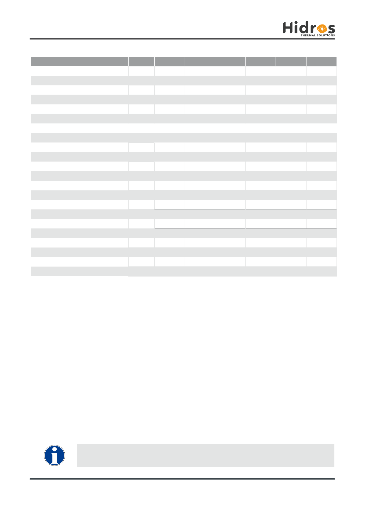
HMA/Z 270 350 450 550 750 950
l/24h 263,1 340,2 418,8 566,8 751,1 939,3
l/24h 185,1 262,3 336,3 425,0 596,4 759,7
l/24h 161,4 233,5 302,0 375,7 534,3 680,3
l/24h 111,4 168,5 223,9 267,1 391,0 501,0
l/24h 75,6 118,3 160,9 180,2 269,8 349,6
kW 12,93 16,96 19,83 25,57 35,56 43,17
kW 4,48 5,91 7,20 8,80 12,45 15,50
kW 4,38 5,69 9,04 10,09 15,52 20,01
kW 6,3 7,8 9,8 14,0 18,9 22,9
A 11,0 14,0 18,2 25,6 34,4 44,1
A 46,0 59,0 77,0 93,0 114,0 159,0
m3/h 3500 4200 4200 5500 7000 8500
m3/h 7500 7100 6700 15000 14200 21300
Pa 50÷150 50÷150 50÷150 50÷150 50÷150 50÷150
R410A R410A R410A R410A R410A R410A
Kg 6,0 5,0 5,5 10,0 14,8 12,0
2088 2088 2088 2088 2088 2088
t 12,52 10,44 11,48 20,88 30,90 25,05
dB(A) 70 71 71 73 73 73
dB(A) 63 64 64 66 66 66
dB(A) 39 41 40 40 42 43
V/Ph/Hz 400/3+N/50 400/3+N/50 400/3+N/50 400/3+N/50 400/3+N/50 400/3+N/50
I dati relativi alla carica del refrigerante possono cambiare senza preavviso; è perciò necessario fare SEMPRE
riferimento all’etichetta argentata posta sull’unità.
MTEC.6710.GB-D-1 Operation and maintenance manual HMA/Z series English
HMA/Z Industrial dehumidiers with temperature control
Performances are calculated with low fan speed and are referred to the following conditions:
(1) Sound Power level according to ISO 9614 fan with available static pressure 50 Pa.
(2)Sound pressure level measured at 1 mt from the unit in free eld conditions according to ISO 9614. fan with available static pressure 50 Pa.
(3)Sound pressure level measured at 10 mt from the unit in free eld conditions according to ISO 9614. fan with available static pressure 50 Pa.
3.3 Technical data
Moisture removed at 30°C - 80%
Moisture removed at 30°C - 60%
Moisture removed at 27°C - 60%
Moisture removed at 20°C - 60%
Moisture removed at 10°C - 70%
Total cooling cap. (30°C-80% - 35°C ext)
Sensible cooling cap. (30°C-80% - 35°C ext)
Nominal input power at 30°C-80%
Maximum input power
Maximum input current
Peak current
Air Flow indoor unit
Air Flow outdoor unit
Available static pressure
Refrigerant
Refrigerant charge
Global warming potential (GWP)
Equivalent CO2charge
Sound power (1)
Sound pressure (2)
Sound pressure (3)
Power supply
The refrigerant data may change without notice. It is therefore necessary to refer always to the silver label placed
on the unit.

Rev. D 02-2021
15
0
100
200
50
150
250
300
3000 3200 3400 3600 3800 4000 4200 4400 4600
0
50
100
150
200
250
300
3600 3800 4000 4200 4400 4600 4800 5000
0
100
200
50
150
250
300
3600 3800 4000 4200 4400 4600 4800 5000
0
200
400
600
100
300
500
4600 4800 5000 5200 5400 5600 5800 6000 6200 6400
0
200
400
500
100
300
6000 6200 6400 6600 6800 7000 7200 7400 7600 7800 8000
0
200
100
300
500
400
600
7400 7600 7800 8000 8200 8400 8600 8800 9000
A
B
A
B
A
B
A
B
A
B
A
B
Min Nominal Max
Min Nominal Max
Min Nominal Max Min Nominal Max
Min Nominal Max
Min Nominal Max
HMA 270 HMA 350
HMA 450 HMA 550
HMA 950HMA 750
(m3/h)
(m3/h)
(m3/h)
(m3/h)
(m3/h)
(m3/h)
(Pa)(Pa)(Pa)
(Pa)(Pa)(Pa)
270 350 450 550 750 950
$+LJKVSHHG kW 0,73 1,36 1,36 1,53 3,30 3,80
A 1,50 2,80 2,80 3,60 5,50 6,70
B (Low speed) kW 0,68 0,73 0,73 1,18 3,10 3,60
A 1,40 1,50 1,50 2,20 5,20 6,40
MTEC.6710.GB-D-1 Operation and maintenance manual HMA/Z series English
HMA/Z,QGXVWULDOGHKXPLGL¿HUVwith temperature control
3.3.1 Fans (standard - indoor unit)3.3.1 Fans
Input power
Input current
Input power
Input current
,QRUGHUWRHQDEOHWKHSURSHUIXQFWLRQLQJRIWKHXQLWLVLPSRUWDQWWRHQVXUHDFRQVWDQWDLUÀRZWRWKHXQLWFORVHWRWKH
QRPLQDOVWDWHGYDOXH7KHPD[LPXPGHYLDWLRQDOORZHGLV
Rev. D 02-2021
16
0
3000 3200 3400 3600 3800 4000 4200 4400 4600
100
200
300
400
500
0
100
200
300
400
500
3600 3800 4000 4200 4400 4600 4800 5000
0
100
200
300
400
500
3600 3800 4000 4200 4400 4600 4800 5000
0
100
200
300
400
500
4500 5000 5500 60004750 5250 5750 6250 6500
0
100
200
300
400
500
6000 6500 7000 7500 80006250 6750 7250 7750
0
100
200
300
400
7500 8000 8500 90007750 8250 8750 9250 9500
Min Nominal Max Min Nominal Max
Min Nominal Max Min Nominal Max
Min Nominal Max Min Nominal Max
A
B
C
F
D
E
A
B
C
F
D
E
A
B
C
F
D
E
A
B
C
F
D
E
A
B
C
F
D
E
A
B
C
F
D
E
(m3/h)
(m3/h)
(m3/h)
(m3/h)
(m3/h)
(m3/h)
(Pa)(Pa)(Pa)
(Pa)(Pa)(Pa)
HMA 270 HMA 350
HMA 450 HMA 550
HMA 950HMA 750
270 350 450 550 750 950
kW A kW A kW A kW A kW A kW A
A0,76 3,30 1,11 4,80 1,11 4,80 1,53 2,70 2,34 3,90 3,16 5,10
B0,46 2,00 0,55 2,40 0,55 2,40 0,95 1,70 1,48 2,60 2,42 4,10
C0,75 3,20 1,16 5,00 1,16 5,00 1,53 2,70 2,43 4,00 3,52 5,60
D0,55 2,40 0,78 3,30 0,78 3,30 1,07 2,06 2,04 3,44 3,14 5,07
E0,44 1,90 0,62 2,70 0,62 2,70 0,92 1,69 1,70 3,01 2,75 4,57
F0,73 3,10 1,14 4,90 1,14 4,90 1,49 2,60 2,42 4,10 3,60 5,70
MTEC.6710.GB-D-1 Operation and maintenance manual HMA/Z series English
HMA/Z,QGXVWULDOGHKXPLGL¿HUVZLWKWHPSHUDWXUHFRQWURO
3.3.2 E.C. Supply fan (VECE) (accessory - indoor unit)3.3.2 E.C. Supply fan (VECE) (accessory)
EC fan electrical data
,QRUGHUWRHQDEOHWKHSURSHUIXQFWLRQLQJRIWKHXQLWLVLPSRUWDQWWRHQVXUHDFRQVWDQWDLUÀRZWRWKHXQLWFORVHWRWKH
QRPLQDOVWDWHGYDOXH7KHPD[LPXPGHYLDWLRQDOORZHGLV

Rev. D 02-2021
17
2
NO
1345678 2
NO
1345678
OK NO
2
NO
1345678
2
NO
1345678 2
NO
1345678 2
NO
1345678 2
NO
1345678
2
NO
1345678 2
NO
1345678 2
NO
1345678
2
NO
1
R1
3V
4V
5V
6V
7V
8V
9V
10V
R10 R2 R3 R4 R5 R6 R7 R8 R9
345678
V1
V5
V2
V6
V3
V7
V4
V8
MTEC.6710.GB-D-1 Operation and maintenance manual HMA/Z series English
HMA/Z,QGXVWULDOGHKXPLGL¿HUVwith temperature control
$OOXQLWVDUHIDFWRU\VHWZLWKWKHQRPLQDODLUÀRZUDWHVDQGDYDLODEOHVWDWLFSUHVVXUHRI3D
The use of the minimum speed ( 1 and 2 ) must be carefully evaluated by skilled personnel because the operation at
very low fan speed could result in malfunction or even damage to the unit.
It is recommended to move a single micro switch for each operating speed . The displacement of two or more micro
switches may generate incorrect power supply voltages with malfunction or damage to the unit .
)DQVSHHGVHWWLQJ
V1 = Minimum speed V8 = Maximum speed
3.3.3 Supply fan Microswitches (Only with VECE - indoor unit)
$OOXQLWVHTXLSSHGZLWK(&IDQVDUHVXSSOLHGZLWKPLFURVZLWFKHVIRUWKHPDQDJHPHQWRIWKHVSHHGRIURWDWLRQ7KHPLFURVZLWFKHVFRQ¿JX-
UDWLRQLVGRQHDWWKHIDFWRU\EXWFDQEHPRGL¿HGE\WKHXVHUDFFRUGLQJWRWKHVSHFL¿FSODQWUHTXLUHPHQWV,QGLFDWLYHO\LWFDQEHFRQVLGHUHG
that the displacement of the micro switch from one number to the next or previous leads to an increase/decrease of the available static
SUHVVXUHRIDERXW·3DDWQRPLQDODLUÀRZ

Rev. D 02-2021
18
40
30
60
50
80
70
100
90
1050 152025303540
5
0
15
10
25
20
35
30
1050 15202530354045
MTEC.6710.GB-D-1 Operation and maintenance manual HMA/Z series English
HMA/Z,QGXVWULDOGHKXPLGL¿HUVZLWKWHPSHUDWXUHFRQWURO
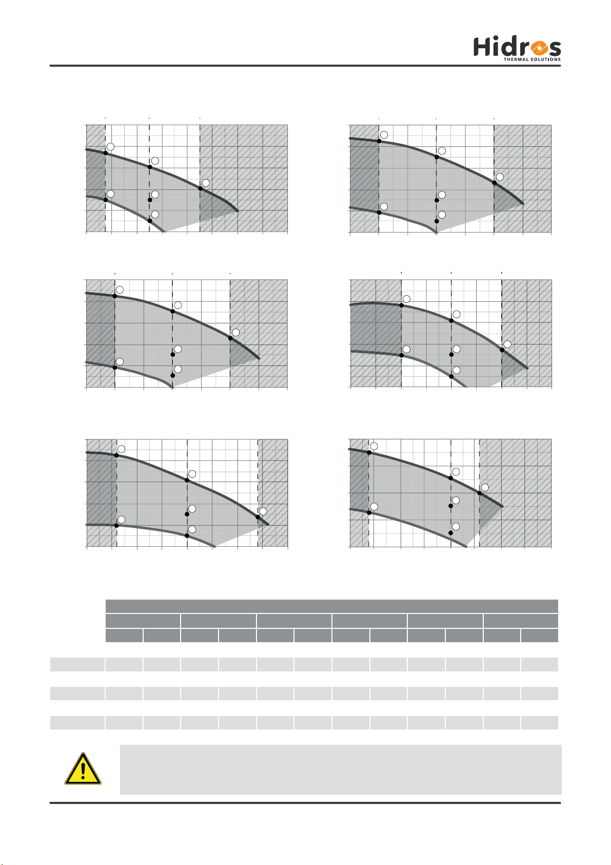
3.4 Operation limits
The units MUST be used within the operation limit indicated in the diagrams (see above). the warranty will be inva-
lidated if the units are used in ambient conditions outside the limits reported. If there is the necessity to operate in
GLIIHUHQWFRQGLWLRQVSOHDVHFRQWDFWRXUWHFKQLFDORI¿FH
RH (%)
Room temperature (°C)
The units are designed to operate within false ceiling and/or heated technical room. The units are NOT suitable for
outdoor installations and / or technical room w/o heat (attics, rooms communicating with the outside) as it may form
condensation on the walls and inside the unit cabinet causing damages.
The units are designed to work in clean ambients and with the standard characteristics of the ambient air.
It’s suitable not to install the unit in swimming pools or ambient with polluted and/or aggressive air.
Contact the Company in case of necessity.
Outdoor ambient temperature (°C)
Indoor ambient temperature (°C)

Rev. D 02-2021
19
Modd.
Lw Lp1
63 125 250 500 1K 2K 4K 8K dB dB(A) dB(A)
dB dB dB dB dB dB dB dB
270 83,1 74,3 68,2 66,7 65,6 60,2 56,8 47,7 83,9 70 63
350 84,1 75,3 69,2 67,7 66,6 61,2 57,8 48,7 84,9 71 64
450 84,1 75,3 69,2 67,7 66,6 61,2 57,8 48,7 84,9 71 64
550 86,1 77,3 71,2 69,7 68,6 63,2 59,8 50,7 86,9 73 66
750 86,1 77,3 71,2 69,7 68,6 63,2 59,8 50,7 86,9 73 66
950 86,1 77,3 71,2 69,7 68,6 63,2 59,8 50,7 86,9 73 66
Modd.
Lw Lp2
63 125 250 500 1K 2K 4K 8K dB dB(A) dB(A)
dB dB dB dB dB dB dB dB
270 59,1 50,3 44,2 42,7 41,6 36,2 32,8 23,7 59,9 46 39
350 61,1 52,3 46,2 44,7 43,6 38,2 34,8 25,7 61,9 48 41
450 60,1 51,3 45,2 43,7 42,6 37,2 33,8 24,7 60,9 47 40
550 60,1 51,3 45,2 43,7 42,6 37,2 33,8 24,7 60,9 47 40
750 62,1 53,3 47,2 45,7 44,6 39,2 35,8 26,7 62,9 49 42
950 63,1 54,3 48,2 46,7 45,6 40,2 36,8 27,7 63,9 50 43
MTEC.6710.GB-D-1 Operation and maintenance manual HMA/Z series English
HMA/Z,QGXVWULDOGHKXPLGL¿HUVwith temperature control
3.5 Sound data
Sound data - indoor unit
2FWDYHEDQG+]
Sound data - outdoor unit
2FWDYHEDQG+]
Lw: Sound power level according to ISO 9614 fan with available static pressure 50 Pa.
/S6RXQGSUHVVXUHOHYHOPHDVXUHGDWPWIURPWKHXQLWLQIUHH¿HOGFRQGLWLRQVGLUHFWLRQIDFWRU4 DFFRUGLQJWR,62fan with available static
pressure 50 Pa.
/S6RXQGSUHVVXUHOHYHOPHDVXUHGDWPWIURPWKHXQLWLQIUHH¿HOGFRQGLWLRQVGLUHFWLRQIDFWRU4 DFFRUGLQJWR,62fan with available static
pressure 50 Pa.
3.6 Safety devices
+LJKSUHVVXUHVZLWFK
The high pressure switch stops the unit when the discharge compressor pressure is higher than the set value. The restart is automatic, done
when the pressure is under the level set in the differential value.
3.6.2 Defrost sensor
It’s a device which signals to the electronic control, the necessity to make the defrost cycle. Once the defrost cycle is activated, the defrost
sensor also determines termination.
'HIURVWLQJ
7KHIURVWRQWKHFRLOREVWUXFWVWKHDLUÀRZUHGXFHVWKHDYDLODEOHH[FKDQJHDUHDDQGFRQVHTXHQWO\WKHXQLWSHUIRUPDQFHVDQGFDQVHULRXVO\
damage the system. All the units are supplied, standard, with a control which defrost automatically the heat exchanger if necessary. This
control provides a temperature probe (defrost thermostat) on the unit evaporator. When the defrost cycle is required, the microprocessor
control (according to set parameters), switches the compressor off, while the fan remains in operation. At the end of the defrost cycle, there
is a timer delay to allow condensate water to clear from the coil.
Rev. D 02-2021
20
MTEC.6710.GB-D-1 Operation and maintenance manual HMA/Z series English
HMA/Z,QGXVWULDOGHKXPLGL¿HUVZLWKWHPSHUDWXUHFRQWURO
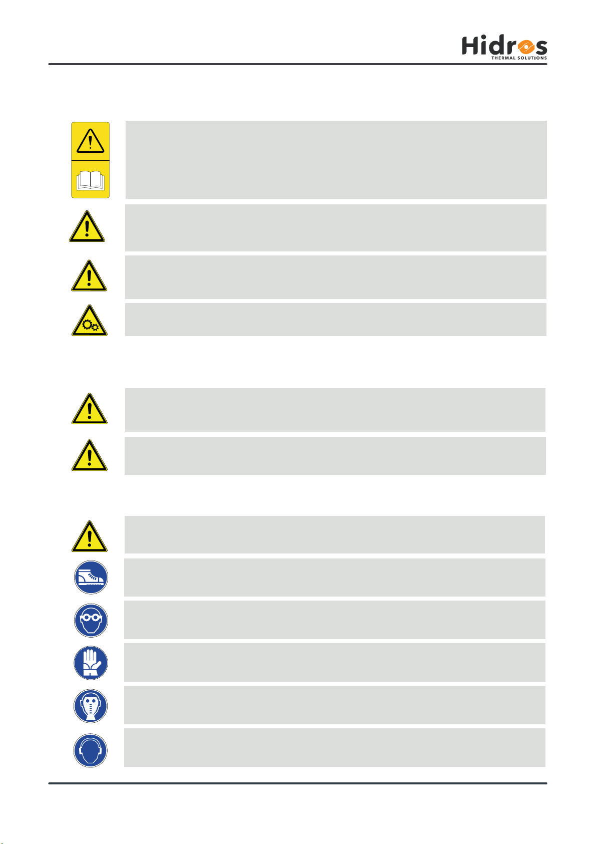
4. INSTALLATION
Before undertaking any task the operator must be fully trained in the operation of the machines to be used and
their controls. They must also have read and be fully conversant with all operating instructions.
All maintenance must be performed by TRAINED personnel and be in accordance with all national and local regu-
lations.
The installation and maintenance of the unit must comply with the local regulations in force at the time of the installa-
tion.
Avoid contact and do not insert any objects into moving parts.
*HQHUDOVDIHW\JXLGHOLQHVDQGDQGXVHRIV\PEROV
When operating and maintaining the unit, use the following personal protective equipment listed below as required
by law.
Protective footwear.
Eye protection.
Protective gloves.
Respiratory protection.
Hearing protection.
4.2 Health and safety Considerations
4.3 Personal protective equipment
The workplace must be kept clean, tidy and free from objects that may prevent free movement. Appropriate ligh-
ting of the work place shall be provided to allow the operator to perform the required operations safely. Poor or too
strong lighting can cause risks.
Ensure that work places are always adequately ventilated and that respirators are working, in good condition and
comply fully with the requirements of the current regulations.
This manual suits for next models
6
Table of contents
Other HIdRos Dehumidifier manuals

HIdRos
HIdRos HHA Series User manual

HIdRos
HIdRos SDA Series User manual

HIdRos
HIdRos SHH Series User manual

HIdRos
HIdRos SRH Series User manual

HIdRos
HIdRos HMA BT Series User manual

HIdRos
HIdRos SRH Series User manual

HIdRos
HIdRos iCHiLL 100CX User manual

HIdRos
HIdRos HDA Series User manual

HIdRos
HIdRos GH Series User manual

HIdRos
HIdRos SHA Series User manual


