HIdRos SHH Series User manual
SWIMMING POOL DEHUMIDIFIERS
SHH
SERIE
TECHNICAL MANUAL

SHH Swimming pool dehumidifiers
MTSHHGB REV.072008
2

SHH Swimming pool dehumidifiers
MTSHHGB REV.072008
3

SHH Swimming pool dehumidifiers
MTSHHGB REV.072008
4

SHH Swimming pool dehumidifiers
MTSHHGB REV.072008
5
INDEX
Declaration of conformity page 3
Aim and contents of this manual page 6
How to keep this manual page 6
Graphyc symbols page 6
Safety laws page 7
General safety guidelines page 7
Worker’s health and safety page 8
Protective equipment page 8
Safety signs page 8
Technical description page 9
Accessories page 10
Technical data page 11
Hot water coil page 17
Partial heat recovery page 18
Operation limits page 19
Sound data page 19
Safety devices page 20
Safety device setting page 20
Electrical data page 20
Inspection page 21
Lifting and handling page 21
Location and minimum technical clearances page 21
Condensate draining connections page 22
Duct unit connection page 23
Refrigerant lay-out page 24
Electrical connections page 25
Start up page 25
Control panel page 26
Unit switch off page 27
Refrigerant charge checking page 28
Energy saving page 28
Maintenance and periodic checks page 28
Refrigerant circuit repair page 28
Environment protection page 28
Unit out of service page 28
Unit under alarm page 29
Fault finding page 29
Wiring diagrams page 30
Dimensions page 50
SHH Swimming pool dehumidifiers
MTSHHGB REV.072008
6
The SHH manual, contains any information that is needed for a correct use of the equipment while safeguarding operator safety,
according to what indicated in the actual directives on units safety.
AIM AND CONTENTS OF THIS MANUAL
This manual provides basic information on the installation, operation and maintenance off the SHH unit. It is addressed to machine
operators and it enables them to use the equipment efficiently, even if they do not have any previous specific knowledge of it.
This manual describes the characteristics of the equipment at the time it is being put on the market; therefore it may not capture later
technological improvements introduced by HIDROS SRL as part of its constant endeavour to enhance the performance, ergonomics,
safety and functionality of its products.
HOW TO KEEP THIS MANUAL
The manual must be always with the unit it refers to. It must be stored in a safe place, away from the dust and moisture. It must be
accessible to all users who shall consult it any time they are in doubt on how to operate the equipment.
HIDROS SRL reserves the right to modify its products and related manuals without necessarily updating previous versions of the
reference material. The customer shall store any updated copy of the manual or parts of it delivered by the manufacturer as an
attachment to this manual.
HIDROS SRL is available to give any detailed information about this manual and to give information regarding the use and the
maintenance of its own units.
GRAPHIC SYMBOLS
Indicates operations that can be dangerous for people and/or disrupts the correct operation of the
equipment..
Indicates prohibited operations.
Indicates important information that the operator must follow in order to guarantee the correct operation
of the equipment in complete safety

SHH Swimming pool dehumidifiers
MTSHHGB REV.072008
7
SAFETY LAWS
The units single components or the complete units produced by HIDROS have been designed according to the actual CE and
national Directives. For the detailed list of the project technical Directives, refer to the CE declaration enclosed.
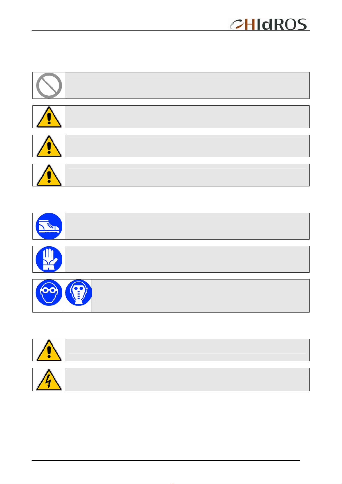
GENERAL SAFETY GUIDELINES
Before beginning to operate on SHH units every user must be perfectly knowledgeable about the functions of the equipment and its
controls and must have read and understood the information container in this manual.
It’s strictly forbidden to remove and/or camper with any safety device.
Any routine or not-routine maintenance operation shall be carried out when the equipment has been shut
down, disconnected from electric and pneumatic power source and after its pneumatic system has been
discharged.
Do not put your hands or insert screwdrivers, spanners or other tools into moving parts of the equipment.
The equipment supervisor and the maintenance man must receive training suitable for the performance of
their tasks in safety
Operators must know how to use personal protective devices and must know the accident-prevention
guidelines contained in national and international laws and norms.
SHH Swimming pool dehumidifiers
MTSHHGB REV.072008
8
WORKERS’ HEALTH AND SAFETY
The European Community has emanated some Directives about worker’s safety and health which the employers have to respect
and make the others respect. For the detailed list, see the CE declaration enclosed.
Do not tamper with or replace parts of the equipment without the specific consent of the manufacturer.
The manufacturer shall have no responsibility whatsoever in case of unauthorised operations.
Using components, expendable materials or spare parts that do not correspond to those recommended
by the manufacturer and/or listed in this manual may be dangerous for the operators and/or damage the
equipment
The operator’s workplace must be kept clean, tidy and free from objects that may camper free
movements. Appropriate lighting of the work place shall be provided so as to allow the operator to carry
out the required operations safely. Poor or too strong lighting can cause risks.
Ensure that work places are always adequately ventilated and that aspirators are working, in good
condition and in compliance with the requirements of the laws in force...
PERSONAL PROTECTIVE EQUIPMENT
When operating and maintaining the SHH unit, use the following personal protective equipment.
Equipment: people who make maintenance or work with the unit, must wear an equipment in accordance
with the safety Directives. They must wear accident prevention shoes with anti-slip sole where the paving
is slippery.
Gloves: During the cleanings and the maintenance operations, it’s necessary the use of appropriate
gloves. In case of gas recharge, it’s compulsory the use of appropriate gloves to avoid the risk of
freezing.
Mask and googles: Respiratory protection (mask) and eye protection (goggles) should be
used during cleaning and maintenance operations.
SAFETY SIGNS
The equipment features the following safety signs, which must be complied with:
General hazard
Electric shock hazard

SHH Swimming pool dehumidifiers
MTSHHGB REV.072008
9
TECHNICAL DESCRIPTION
SHH dehumidifiers series are high-performances units especially designed for swimming pool applications or where humidity level
should be controlled or water vapour condensation should be prevented.
Frame
All SHH units are made from hot-galvanised thick sheet metal, painted with polyurethane powder enamel at 180°C to ensure the
best resistance against the atmospheric agents. The frame is self-supporting with removable panels. The drip tray is present
standard in all SHH units and it’s in stainless steel. The colour of the units is RAL 7035
Refrigerant circuit
The refrigerant gas used in these units is R407C. The refrigerant circuit is made by using international primary brands components
and according to ISO 97/23 concerning welding procedures. The refrigerant circuit includes:
sight glass,
filter drier,
thermal expansion valve with external equalizer,
Schrader valves form maintenance and control,
pressure safety device (according to PED regulation)
Compressors
The compressor is scroll type with crankcase heater and thermal overload protection by a klixon embedded in the motor winding. It’s
mounted on rubber vibration dampers and, by request, it can be supplied with some jackets to reduce the noise (accessory). The
crankcase heater, when present, is always powered when the compressor is in stand-by. The inspection is possible through the
frontal panel of the unit.
Condensers and evaporators
Condensers and evaporators are made of copper pipes and aluminium fins. All evaporators are painted with epoxy powders to
prevent corrosion problem due to their use in aggressive environments. The diameter of the copper pipes is 3/8” and the thickness of
the aluminium fins is 0,1 mm. The tubes are mechanically expanded into the aluminium fins to improve the heat exchange factor.
The geometry of these heat exchangers guarantees a low air side pressure drop and then the use of low rotation (and low noise
emission) fans. All units are supplied, standard, with a Stainless steel drip tray and all evaporators are supplied with a temperature
sensor used as automatic defrost probe.
Fans
The fan is centrifugal type. It’s statically and dynamically balanced and supplied complete of the safety fan guard according to EN
294. It’s mounted on the unit frame by interposition of rubber vibration dampers. The electric motor is at 4 poles (about 1500 rpm).
Connected to the fan by belts and pulleys and it’s equipped of an integrated thermal overload protection. The protection class of the
motors is IP 54.
Air Filter
It’s supplied standard with the unit. It’s made of filtering material in synthetic fibre without electrostatic charge. It can be removed for
differential disposal, class G3, according to EN 779:2002
Electric box
The electric switch board is made according to electromagnetic compatibility norms CEE 73/23 and 89/336. The accessibility to the
board is possible after removing the front panel of the unit and the OFF positioning of the main switch. The moisture protection
degree is IP44. In all SHH units are installed, standard, the compressors sequence relay who disables the operation of the
compressor in case the power supply phase sequence is not the correct one (scroll compressors in fact, can be damaged if they
rotate reverse wise). The following components are also standard installed: main switch, magnetic-thermal switches (as a protection
of the fans), compressors fuses, control circuit automatic breakers, compressor contactors. The terminal board is also supplied with
voltage free contacts for remote ON-OFF.
Microprocessors
All SHH units are supplied standard with microprocessor controls. The microprocessor controls the following functions: compressor
timing, automatic defrost cycles, the management of fresh and exhaust air, post heating valve and alarms. An appropriate LCD
display shows the operation mode of the unit, set point and alarms

SHH Swimming pool dehumidifiers
MTSHHGB REV.072008
10
Control and protection devices
All units are supplied with the following control and protection devices: defrost thermostat, who signals to the microprocessor control
that a defrost cycle is needed and controls its termination, high pressure switch with manual reset, low pressure switch with
automatic reset, high pressure safety valve, compressor thermal overload protection, fans thermal overload protection
Test
All the units are fully assembled and wired at the factory, carefully evacuated and dried after leak tests under pressure and then
charged with refrigerant R407C. They are all fully operational tested before shipment. They all conform to European Directives and
are individually marked with the CE label and provided with Conformity Declaration
ACCESSORIES
Remote mechanical hygrostat: Supplied with a regulation knob and working range from 30% to 100% with precision of 3%.
Condensate discharge pump: Centrifugal package type, with high available static pressure, itis supplied with water tank,
one way valve and floating sensor device. The pump is supplied with an alarm contact who
stops the compressor operation in case the pump does not run properly.
Partial heat recovery: It is used to produce hot sanitary water or to warm up the pool; it is made of AISI 316
stainless steel braze-welded plates type with molybdenum alloy; for its operation it is required
a water connection to sanitary water or pool water.
Hot water coil: The hot water coil is made of copper pipes and aluminium fins. The diameter of the copper
pipes is 3/8” and the thickness of the aluminium fins is 0,1 mm. The tubes are mechanically
expanded into the aluminium fins to improve the heat exchange factor.
On/Off 3 way valve kit: To be supplied to control the water flow in the hot water coil. The valve is controlled by the
unit microprocessor.
Version for outdoor installation: Suitable for outdoor installation.
Air filter with ducted installation: Complete with EU2 efficiency air filter which can be removed by the side and frame for ducted
installation.
Low noise version (LS): The low noise version LS includes the complete insulation of the compressor vane with high
density sound absorption material.

SHH Swimming pool dehumidifiers
MTSHHGB REV.072008
11
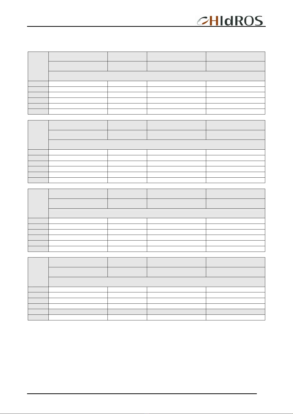
TECHNICAL DATA
Mod. 330 400 560 740 940
Refrigerant R407C R407C R407C R407C R407C
Dehumidification capacity (1) l/24h 329,9 414,8 564,1 738,5 937,3
Cooling capacity (2) kW --- --- --- --- ---
Compressor input power (1) kW 5,3 6,6 8,7 11,7 15,6
Maximum input power (1) kW 5,8 7,3 9,5 12,8 17,1
Partial heat recovery(3) kW 4,8 5,8 8 10,5 13,5
Hot water coil(4) kW 21,8 21,8 36,2 46 55,7
Nominal input current (1) A 13,5 15,3 16 19,4 25,2
Maximum input current (2) A 14,2 16,5 18,4 21,2 24,7
Power supply V/Ph/Hz 400/3+N/50
Total air flow m3/s 1,055 1,055 1,430 1,903 2,277
Supply fan available static pressure Pa 230 230 250 250 250
tipo SCROLL
Compressor n° 1 1 1 1 1 1
Refrigerants circuits n° 1 1 1 1 1 1
Steppower control 1 1 1 1 1 1
Sound power level (5) dB(A) 74 75 79 80 81
Sound pressure level (6) dB(A) 67 69 72 73 74
Length mm 1004 1004 1630 1630 1630
Width mm 635 635 1010 1010 1010
Height mm 1283 1283 1410 1410 1410
Weight Kg 195 209 405 421 450
Performances are referred to the following conditions:
(1) Ambient temperature 30 °C relative humidity 80%.
(2) Ambient temperature 35 °C relative humidity 80%;
(3) Water temperature inlet/outlet 25/30°C.
(4) Room temperature 32°C; Water temperature 80/70°C.
(5) Sound power level calculated according to ISO 3746.
(6) Sound pressure level measured in free field, at 1 mt from the unit, directional factor Q=2 according to ISO 3746.
SHH Swimming pool dehumidifiers
MTSHHGB REV.072008
12
SHH 330
PERFORMANCE TABLES
Dehumidification capacity Input Power Air temperature increase Thermal load in the room
[l/24h] [kW] [°C] [kW]
Ambient
temperature
Relative humidity 50%
10°C 47,3 2,8 3,2 4,6
15°C 58,0 3,0 3,6 5,1
20°C 84,8 3,4 4,5 6,3
25°C 122,3 3,8 5,8 7,9
30°C 158,4 4,4 7,0 9,5
35°C 190,1 4,9 8,1 10,9
Dehumidification capacity Input Power Air temperature increase Thermal load in the room
[l/24h] [kW] [°C] [kW]
Ambient
temperature
Relative humidity 60%
10°C 62,2 2,8 3,6 5,1
15°C 86,1 3,1 4,3 6,1
20°C 119,1 3,5 5,4 7,4
25°C 167,7 4,0 6,9 9,3
30°C 215,9 4,5 8,4 11,2
35°C 255,7 5,0 9,7 12,9
Dehumidification capacity Input Power Air temperature increase Thermal load in the room
[l/24h] [kW] [°C] [kW]
Ambient
temperature
Relative humidity 70%
10°C 80,2 2,9 4,0 5,7
15°C 113,3 3,2 5,0 7,0
20°C 158,9 3,6 6,4 8,7
25°C 210,7 4,1 7,9 10,7
30°C 269,9 4,7 9,7 13,0
35°C 306,9 5,2 11,0 14,5
Dehumidification capacity Input Power Air temperature increase Thermal load in the room
[l/24h] [kW] [°C] [kW]
Ambient
temperature
Relative humidity 80%
10°C 98,3 2,9 4,4 6,2
15°C 142,2 3,2 5,7 7,8
20°C 198,7 3,7 7,3 9,9
25°C 258,0 4,2 9,1 12,1
30°C 329,9 4,8 11,2 14,8
35°C 370,1 5,3 12,5 16,5
NOTE Shadowed fields refer to nominal condition capacities.

SHH Swimming pool dehumidifiers
MTSHHGB REV.072008
13
SHH 400
PERFORMANCE TABLES
Dehumidification capacity Input Power Air temperature increase Thermal load in the room
[l/24h] [kW] [°C] [kW]
Ambient
temperature
Relative humidity 50%
10°C 60,8 3,5 3,9 5,8
15°C 74,5 3,7 4,4 6,4
20°C 108,4 4,3 5,5 7,9
25°C 155,4 4,9 6,9 9,9
30°C 200,4 5,6 8,4 11,9
35°C 240,4 6,2 9,7 13,6
Dehumidification capacity Input Power Air temperature increase Thermal load in the room
[l/24h] [kW] [°C] [kW]
Ambient
temperature
Relative humidity 60%
10°C 80,0 3,5 4,3 6,3
15°C 110,3 3,9 5,2 7,6
20°C 151,6 4,4 6,5 9,3
25°C 212,5 5,0 8,3 11,7
30°C 272,4 5,8 10,1 14,1
35°C 322,5 6,4 11,6 16,2
Dehumidification capacity Input Power Air temperature increase Thermal load in the room
[l/24h] [kW] [°C] [kW]
Ambient
temperature
Relative humidity 70%
10°C 103,0 3,6 4,9 7,1
15°C 144,7 4,0 6,1 8,7
20°C 201,9 4,6 7,7 10,9
25°C 266,5 5,2 9,6 13,4
30°C 340,1 6,0 11,7 16,3
35°C 386,7 6,6 13,2 18,3
Dehumidification capacity Input Power Air temperature increase Thermal load in the room
[l/24h] [kW] [°C] [kW]
Ambient
temperature
Relative humidity 80%
10°C 126,2 3,6 5,4 7,7
15°C 181,3 4,1 6,9 9,8
20°C 251,9 4,7 8,9 12,4
25°C 325,6 5,3 10,9 15,2
30°C 414,8 6,1 13,4 18,6
35°C 465,2 6,8 15,0 20,7
NOTE Shadowed fields refer to nominal condition capacities.

SHH Swimming pool dehumidifiers
MTSHHGB REV.072008
14
SHH 560
PERFORMANCE TABLES
Dehumidification capacity Input Power Air temperature increase Thermal load in the room
[l/24h] [kW] [°C] [kW]
Ambient
temperature
Relative humidity 50%
10°C 83,0 4,9 4,2 8,0
15°C 101,5 5,2 4,7 8,9
20°C 147,2 5,8 5,8 10,8
25°C 210,7 6,5 7,3 13,4
30°C 271,3 7,4 8,8 16,0
35°C 324,2 8,1 10,1 18,2
Dehumidification capacity Input Power Air temperature increase Thermal load in the room
[l/24h] [kW] [°C] [kW]
Ambient
temperature
Relative humidity 60%
10°C 109,3 4,9 4,6 8,8
15°C 150,2 5,3 5,6 10,4
20°C 206,2 5,9 6,8 12,6
25°C 288,6 6,7 8,6 15,7
30°C 369,5 7,5 10,5 18,9
35°C 435,9 8,3 12,0 21,6
Dehumidification capacity Input Power Air temperature increase Thermal load in the room
[l/24h] [kW] [°C] [kW]
Ambient
temperature
Relative humidity 70%
10°C 140,6 5,0 5,2 9,8
15°C 197,1 5,5 6,4 11,9
20°C 247,5 6,1 8,1 14,8
25°C 362,0 6,9 10,0 18,1
30°C 461,6 7,7 12,1 21,8
35°C 522,8 8,6 13,6 24,4
Dehumidification capacity Input Power Air temperature increase Thermal load in the room
[l/24h] [kW] [°C] [kW]
Ambient
temperature
Relative humidity 80%
10°C 172,3 5,0 5,7 10,7
15°C 247,0 5,6 7,3 13,4
20°C 342,8 6,2 8,1 14,8
25°C 442,8 7,0 11,4 20,5
30°C 564,1 7,9 13,9 24,9
35°C 630,5 8,7 15,5 27,6
NOTE Shadowed fields refer to nominal condition capacities.

SHH Swimming pool dehumidifiers
MTSHHGB REV.072008
15
SHH 740
PERFORMANCE TABLES
Dehumidification capacity Input Power Air temperature increase Thermal load in the room
[l/24h] [kW] [°C] [kW]
Ambient
temperature
Relative humidity 50%
10°C 113,5 6,2 4,1 10,5
15°C 138,2 6,6 4,6 11,6
20°C 198,0 7,4 5,7 14,2
25°C 280,5 8,4 7,1 17,6
30°C 358,5 9,5 8,6 20,9
35°C 427,9 10,5 9,9 24,0
Dehumidification capacity Input Power Air temperature increase Thermal load in the room
[l/24h] [kW] [°C] [kW]
Ambient
temperature
Relative humidity 60%
10°C 149,4 6,2 4,5 11,6
15°C 203,4 6,7 5,5 13,7
20°C 276,1 7,5 6,7 16,6
25°C 382,7 8,5 8,5 20,7
30°C 486,5 9,7 10,3 24,8
35°C 573,3 10,8 11,8 28,4
Dehumidification capacity Input Power Air temperature increase Thermal load in the room
[l/24h] [kW] [°C] [kW]
Ambient
temperature
Relative humidity 70%
10°C 191,6 6,3 5,1 13,0
15°C 265,7 7,0 6,3 15,7
20°C 366,3 7,8 7,9 19,4
25°C 478,7 8,8 9,8 23,7
30°C 606,2 10,0 11,9 28,6
35°C 686,2 11,1 13,4 32,0
Dehumidification capacity Input Power Air temperature increase Thermal load in the room
[l/24h] [kW] [°C] [kW]
Ambient
temperature
Relative humidity 80%
10°C 234,9 6,3 5,7 14,2
15°C 331,8 7,1 7,2 17,8
20°C 455,4 7,9 9,1 22,2
25°C 583,5 9,0 11,2 26,9
30°C 738,5 10,2 13,6 32,6
35°C 824,8 11,3 15,2 36,2
NOTE Shadowed fields refer to nominal condition capacities.

SHH Swimming pool dehumidifiers
MTSHHGB REV.072008
16
SHH 940
PERFORMANCE TABLES
Dehumidification capacity Input Power Air temperature increase Thermal load in the room
[l/24h] [kW] [°C] [kW]
Ambient
temperature
Relative humidity 50%
10°C 146,0 8,0 4,4 13,7
15°C 178,0 8,6 5,0 15,2
20°C 254,4 9,6 6,1 18,5
25°C 359,7 11,0 7,7 22,8
30°C 458,3 12,5 9,3 27,2
35°C 547,3 13,8 10,7 31,1
Dehumidification capacity Input Power Air temperature increase Thermal load in the room
[l/24h] [kW] [°C] [kW]
Ambient
temperature
Relative humidity 60%
10°C 192,0 8,0 4,9 15,1
15°C 261,1 8,8 5,9 17,8
20°C 353,7 9,9 7,3 21,6
25°C 489,1 11,2 9,2 26,8
30°C 620,1 12,7 11,1 32,1
35°C 731,3 14,1 12,7 36,7
Dehumidification capacity Input Power Air temperature increase Thermal load in the room
[l/24h] [kW] [°C] [kW]
Ambient
temperature
Relative humidity 70%
10°C 246,4 8,3 5,6 16,9
15°C 340,7 9,1 6,9 20,5
20°C 468,5 10,2 8,6 25,2
25°C 610,9 11,6 10,6 30,7
30°C 771,6 13,1 12,8 36,9
35°C 874,0 14,6 14,4 41,3
Dehumidification capacity Input Power Air temperature increase Thermal load in the room
[l/24h] [kW] [°C] [kW]
Ambient
temperature
Relative humidity 80%
10°C 302,0 8,3 6,1 18,5
15°C 424,7 9,3 7,8 23,0
20°C 580,8 10,4 9,8 28,7
25°C 742,4 11,8 12,0 34,7
30°C 937,3 13,4 14,6 41,9
35°C 1047,8 14,9 16,3 46,6
NOTE Shadowed fields refer to nominal condition capacities.

SHH Swimming pool dehumidifiers
MTSHHGB REV.072008
17
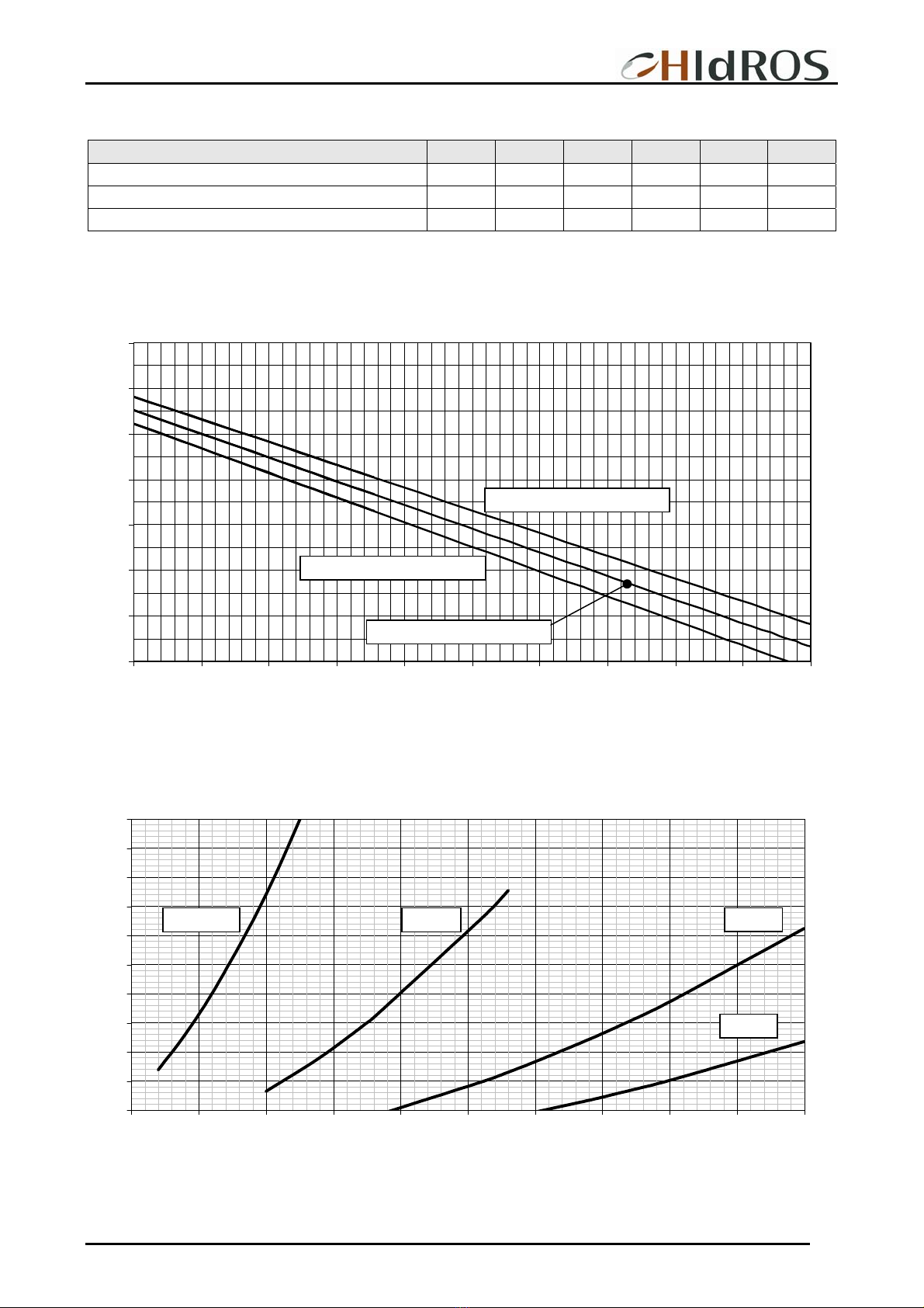
HOT WATER COIL (ACCESSORY)
Mod. 330 400 560 740 940
Hot water coil capacity kW 21,8 21,8 36,2 46 55,7
Water flow l/h 1920 1920 3110 3960 4800
Water pressure drops kPa 22 22 10 11 10
Nominal data are referred to room temperature 32°C and water temperature 80/70°C .
0,3
0,4
0,5
0,6
0,7
0,8
0,9
1
1,1
1,2
1,3
1,4
1,5
20 25 30 35 40 45 50 55 60 65 70
The hot water coil capacity in different conditions can be obtained multiplying the nominal capacity (See above), by the correction
factor indicated in the table.
WATER PRESSURE DROPS
10
15
20
25
30
35
40
1500 1700 1900 2100 2300 2500
5
10
15
20
25
2500 3000 3500 4000 4500 5000 5500
Thermal difference water inlet temperature – room temperature °C
kPa
Heating coil water flow (l/h)
SHH 560
SHH 330-400
kPa
Heating coil water flow (l/h)
SHH 740
SHH 940
SHH Swimming pool dehumidifiers
MTSHHGB REV.072008
18
PARTIAL HEAT RECOVERY (ACCESSORY)
Mod. 330 400 560 740 940
Partial heat recovery nominal capacity kW 4,8 5,8 8,0 10,5 13,5
Water flow l/h 820 1000 1380 1810 2320
Water pressure drops kPa 32 47 25 15 13
The nominal value refers to an ambient temperature of 30°C and outlet water temperature of 32°C (Dt 5°C).
The heat recovery capacity in different conditions can be obtained multiplying the nominal capacity (See above), by the correction
factor indicated in the table.
0,5
0,6
0,7
0,8
0,9
1
1,1
1,2
30 32 34 36 38 40 42 44 46 48 50
Water side pressure drops
10
15
20
25
30
35
40
45
50
55
60
500 750 1000 1250 1500 1750 2000 2250 2500 2750 3000
Ambient temperature 32°C
Ambient temperature 30°C
Ambient temperature 28°C
Outlet water temperature °C
kPa
Partial heat recovery water flow (l/h)
SHH 330-400 SHH 740
SHH 940
SHH 560
SHH Swimming pool dehumidifiers
MTSHHGB REV.072008
19
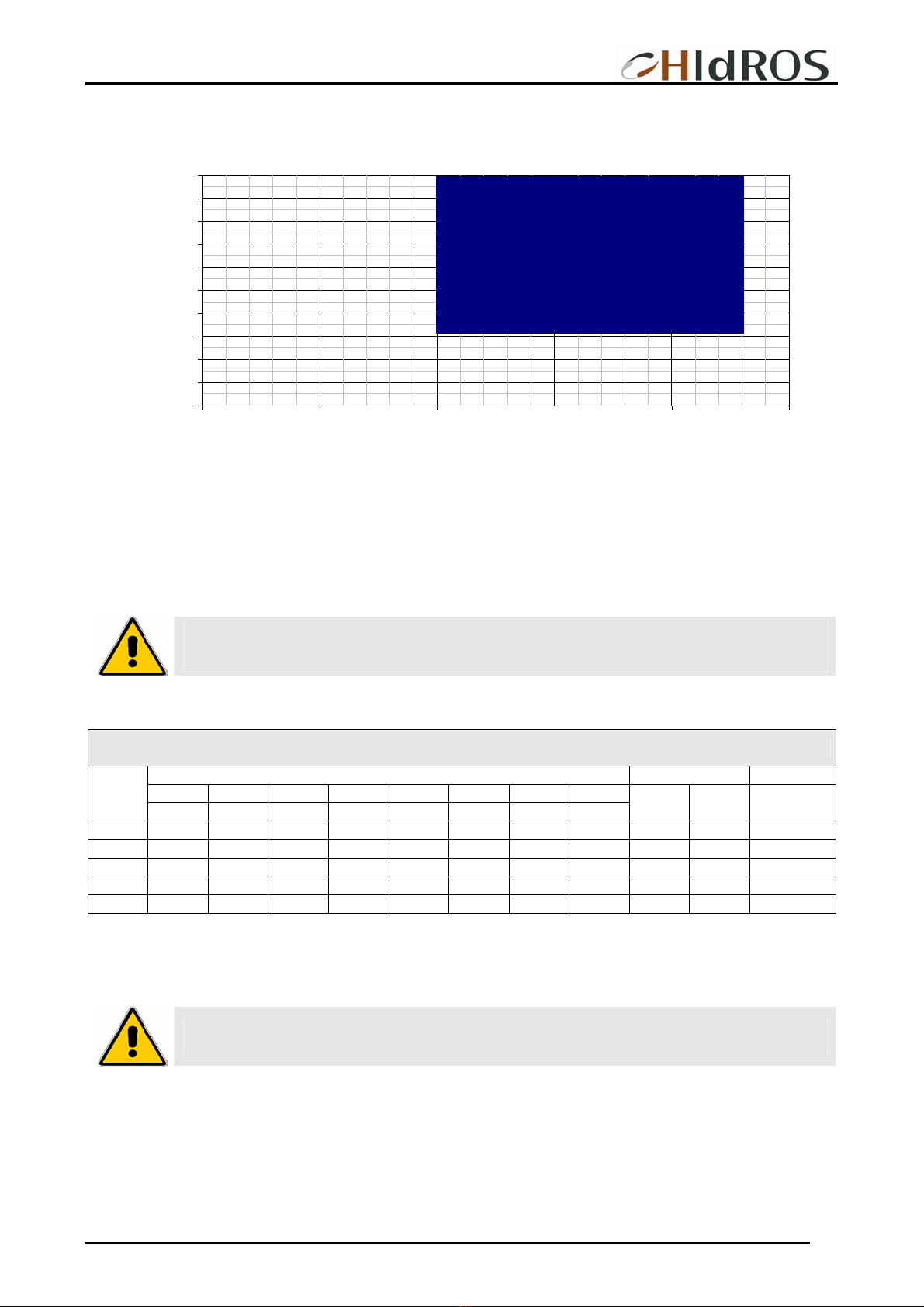
OPERATION LIMITS
Relative humidity (%)
0%
10%
20%
30%
40%
50%
60%
70%
80%
90%
100%
-10 0 10 20 30 40
Air temperature (°C)
Ambient temperatures
SHH units are designed to operate with ambient temperatures from 10°C to 36°C, relative humidity from 50% to 99%
WARNING: The units MUST be used within the operation limit indicated in the diagrams (see above). the
warranty will be invalidated if the units are used in ambient conditions outside the limits reported. If there
is the necessity to operate in different conditions, please contact our technical office
SOUND DATA STANDARD VERSIONS
Octave band (Hz) Lw Lp
63 125 250 500 1K 2K 4K 8K
Mod.
dB dB dB dB dB dB dB dB dB dB(A) dB(A)
330 88,1 79,3 73,2 71,7 70,6 65,2 61,8 52,7 88,9 75 67
400 90,1 81,3 75,2 73,7 72,6 67,2 63,8 54,7 90,9 77 69
560 93,1 84,3 78,2 76,7 75,6 70,2 66,8 57,7 93,9 80 72
740 94,1 85,3 79,2 77,7 76,6 71,2 67,8 58,7 94,9 81 73
940 95,1 86,3 80,2 78,7 77,6 72,2 68,8 59,7 95,9 82 74
Lw: Sound power level according to ISO 3746.
Lp1: Sound pressure level measured at 1 mt from the unit in free field conditions direction factor Q=2 according to ISO 3746.
WARNING: The sound pressure level of the Low noise versions with compressors vane insulation is
approx. 1,5 dB(A) lower than the equivalent standard versions.
Standard operation
99%
SHH Swimming pool dehumidifiers
MTSHHGB REV.072008
20
SAFETY DEVICES
DEFROSTING
The frost on the coil, obstructs the air flow, reduces the available exchange area and consequently the unit performances and can
seriously damage the system. All the units are supplied, standard, with a control which defrost automatically the heat exchanger if
necessary. This control provides a temperature probe (defrost thermostat) on the unit evaporator. When the defrost cycle is required,
the microprocessor control (according to set parameters) starts working (the yellow led turns on), the compressor is switched off
while the fan keeps on working. At the end of the defrost cycle, there is the dripping time (the green led starts flashing
HYGROSTAT (optional)
Hygrostat enables or disables unit operation depending on the humidity value desired.
To verify its correct operation, rotate the control knob clock wise (or set the desired value through the instrument keyboard if a
keyboard instrument should be present) and set the humidity desired value close to lower limit. At this point verify that fan and
compressor (after a time delay) will be started in sequence. Verify as well that the unit is stopped when humidity set is reached
THERMOSTAT (optional)
The thermostat is used when the unit is supplied with hot water coil.
To verify its correct operation, rotate the control knob clock wise (or set the desired value through the instrument keyboard if a
keyboard instrument should be present) and set the temperature desired value close to lower limit. At this point verify the fan is all
the time running and that compressor, after a time delay, is started.
Verify as well that the compressor is stopped when temperature set is reached.
HIGH PRESSURE SWITCH
The high pressure switch stops the unit when the condensing pressure is higher than the set value. The restart is manual (you need
to press the button on the pressure switch) and it can be carried out only when the pressure is under the value indicated by the
differential set (see table below).
LOW PRESSURE SWITCH
The low pressure switch stops the unit when the evaporation pressure is lower than the set value. The restart is automatic and it is
only possible when the pressure back over the value indicated by the differential set (see table below).
DEFROST THERMOSTAT
It’s a device which signals to the electronic control, the necessity to make the defrost cycle. Once the defrost cycle is activated, the
defrost thermostat determines also its conclusion
SAFETY DEVICE SETTING
Device Set-point Differential Reset type
Antifreeze thermostat °C 1 3 MANUAL
High pressure switch Bar 26 7,7 MANUAL
Low pressure switch Bar 0,7 1 MANUAL
ELECTRICAL DATA
Power supply V/~/Hz 400 / 3+N/ 50 Control circuit V/~/Hz 24 / 1 / 50
Auxiliary circuit V/~/Hz 230 / 1 / 50 Fans power supply V/~/Hz 400 / 3 / 50*
* 230/1/50 for SHH 330 and 400.
This manual suits for next models
5
Table of contents
Other HIdRos Dehumidifier manuals

HIdRos
HIdRos HMA/Z Series User manual

HIdRos
HIdRos SHA Series User manual

HIdRos
HIdRos HHA Series User manual

HIdRos
HIdRos SMA Series User manual

HIdRos
HIdRos GHE Series User manual

HIdRos
HIdRos HMA BT Series User manual

HIdRos
HIdRos SRH Series User manual

HIdRos
HIdRos SRH Series User manual

HIdRos
HIdRos HDA Series User manual

HIdRos
HIdRos GH Series User manual


