Parker CDAS HL 050 Series User manual

Compressed Air Dryers
CDAS / OFAS HL 050 - 085
Original Language
User Guide
aerospace
climate control
electromechanical
filtration
fluid & gas handling
hydraulics
pneumatics
process control
sealing & shielding
PL RU
NL DE FR SV NO DA ES IT
EN


CONTENTS
1 Safety Information ........................................................................................................................................................................................1
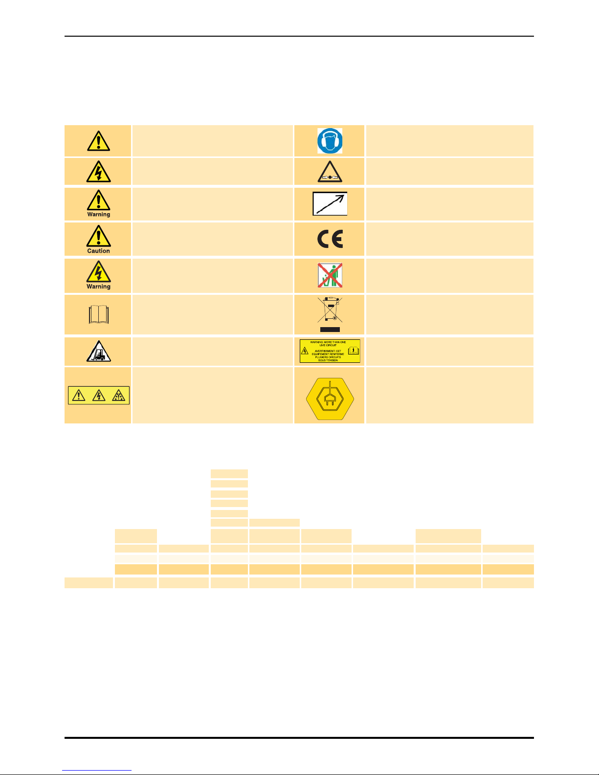
1.1 Markings and Symbols ........................................................................................................................................................................2
1.2 Dryer Model Number Identification.....................................................................................................................................................2
2 Description ....................................................................................................................................................................................................3
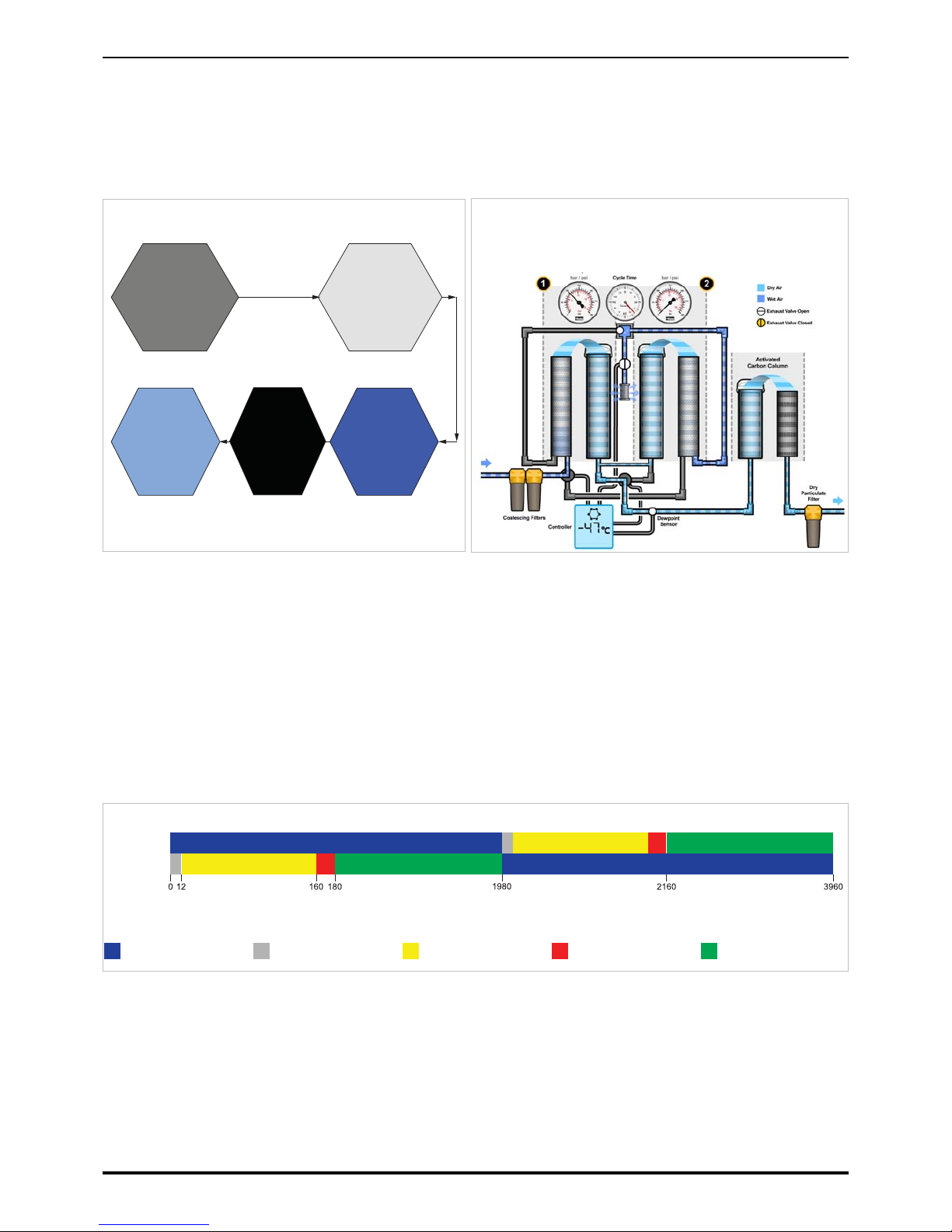
2.1 Overview of Operation .........................................................................................................................................................................3
2.1.1 Operation......................................................................................................................................................................................3
2.2 EST - Energy Saving Technology .......................................................................................................................................................4
2.3 Moisture Over-ride................................................................................................................................................................................5
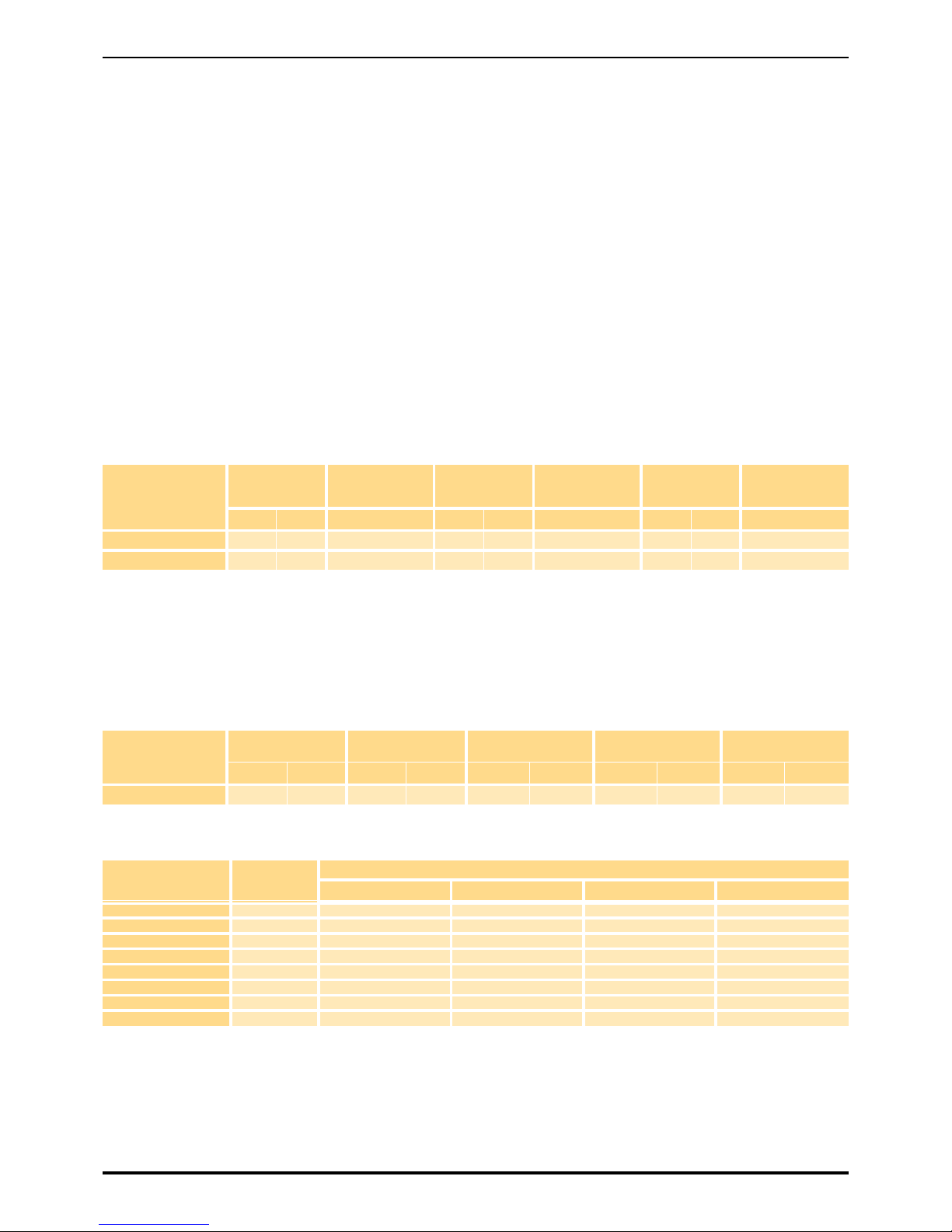
2.4 Technical Specification........................................................................................................................................................................5
2.5 Approvals Compliance and Exemptions............................................................................................................................................7
2.5.1 Approvals .....................................................................................................................................................................................7
2.5.2 3rd Party Performance Verification ..............................................................................................................................................7
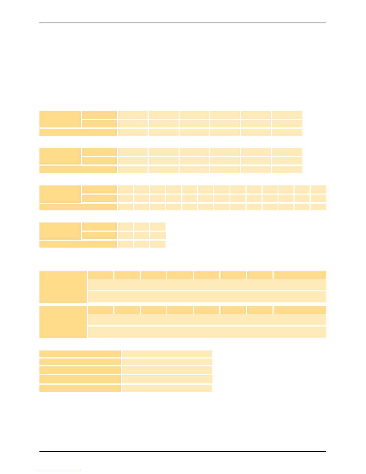
2.6 Weights and Dimensions.....................................................................................................................................................................8
2.7 Receiving and Inspecting the Equipment ........................................................................................................................................10
2.7.1 Storage.......................................................................................................................................................................................10
2.7.2 Unpacking ..................................................................................................................................................................................10
2.8 Overview of the equipment................................................................................................................................................................11
3 Installation and Commissioning................................................................................................................................................................13
3.1 Commissioning Check List ...............................................................................................................................................................13
3.2 Recommended System Layout .........................................................................................................................................................14
3.3 Locating the Equipment.....................................................................................................................................................................15
3.3.1 Environment ...............................................................................................................................................................................15
3.3.2 Space Requirements..................................................................................................................................................................15
3.4 Mechanical Installation ......................................................................................................................................................................15
3.4.1 General Requirements ...............................................................................................................................................................15
3.4.2 Securing the Dryer .....................................................................................................................................................................16
3.4.3 Attach the Exhaust Silencer .......................................................................................................................................................16
3.4.4 Purge Settings............................................................................................................................................................................16
3.5 Electrical Installation..........................................................................................................................................................................17
3.5.1 Dryer Supply...............................................................................................................................................................................17
3.5.2 Dryer Auxilliary Connections ......................................................................................................................................................17
3.5.3 Remote Alarm Connection .........................................................................................................................................................18
3.5.4 Remote Start / Stop (Standby) ...................................................................................................................................................18
3.5.5 Purge Economy..........................................................................................................................................................................19
3.5.6 Dewpoint Selection / Alarm Values ............................................................................................................................................19
3.5.7 Temperature Units......................................................................................................................................................................20
3.5.8 Configuring Inlet Valves .............................................................................................................................................................21
3.6 First Time Start Up .............................................................................................................................................................................21
4 Operating the Dryer ....................................................................................................................................................................................22
4.1 Displays and Indicators .....................................................................................................................................................................22
4.1.1 Column Status Indicators ...........................................................................................................................................................22
4.1.2 Status and Warning Indicators ...................................................................................................................................................23
4.2 Starting the equipment ......................................................................................................................................................................24
4.3 Dryer Shutdown..................................................................................................................................................................................24
5 Servicing......................................................................................................................................................................................................25
5.1 Service intervals ................................................................................................................................................................................25
6 Troubleshooting..........................................................................................................................................................................................29
6.1 Dewpoint Failure.................................................................................................................................................................................29
6.2 High Pressure drop ............................................................................................................................................................................30
6.3 Downstream air supply interrupted ..................................................................................................................................................30
7 Declaration of Conformity..........................................................................................................................................................................31
8 Schematics..................................................................................................................................................................................................32


1
1 Safety Information
Do not operate this equipment until the safety information and instructions in this user guide have been read and understood by all
personnel concerned.
USER RESPONSIBILITY
FAILURE OR IMPROPER SELECTION OR IMPROPER USE OF THE PRODUCTS DESCRIBED HEREIN OR RELATED ITEMS CAN CAUSE
DEATH, PERSONAL INJURY AND PROPERTY DAMAGE.
This document and other information from Parker Hannifin Corporation, its subsidiaries and authorised distributors provide product or system
options for further investigation by users having technical expertise.
The user, through its own analysis and testing, is solely responsible for making the final selection of the system and components and assuring
that all performance, endurance, maintenance, safety and warning requirements of the application are met. The user must analyse all aspects of
the application, follow applicable industry standards, and follow the information concerning the product in the current product catalogue and in
any other materials provided from Parker or its subsidiaries or authorised distributors.
To the extent that Parker or its subsidiaries or authorised distributors provide component or system options based upon data or specifications
provided by the user, the user is responsible for determining that such data and specifications are suitable and sufficient for all applications and
reasonably foreseeable uses of the components or systems.
Only competent personnel trained, qualified, and approved by Parker Hannifin should perform installation, commissioning, service and repair
procedures.
Use of the equipment in a manner not specified within this user guide may result in an unplanned release of pressure, which may cause serious
personal injury or damage.
When handling, installing or operating this equipment, personnel must employ safe engineering practices and observe all related regulations,
health & safety procedures, and legal requirements for safety.
Ensure that the equipment is depressurised and electrically isolated, prior to carrying out any of the scheduled maintenance instructions specified
within this user guide.
Parker Hannifin can not anticipate every possible circumstance which may represent a potential hazard. The warnings in this manual cover the
most known potential hazards, but by definition can not be all-inclusive. If the user employs an operating procedure, item of equipment or a
method of working which is not specifically recommended by Parker Hannifin the user must ensure that the equipment will not be damaged or
become hazardous to persons or property.
Most accidents that occur during the operation and maintenance of machinery are the result of failure to observe basic safety rules and
procedures. Accidents can be avoided by recognising that any machinery is potentially hazardous.
Should you require an extended warranty, tailored service contracts or training on this equipment, or any other equipment within the Parker
Hannifin range, please contact your local Parker Hannifin office.
Details of your nearest Parker Hannifin sales office can be found at www.parker.com/gsfe
Retain this user guide for future reference.

2
1.1 Markings and Symbols
The following markings and international symbols are used on the equipment or within this manual:
1.2 Dryer Model Number Identification
‘
Caution, Read the User Guide. Wear ear protection
Risk of electric shock. Pressurised components on the system
Highlights actions or procedures which, if not performed
correctly, may lead to personal injury or death. Remote control. The dryer may start automatically without
warning.
Highlights actions or procedures which, if not performed
correctly, may lead to damage to this product. Conformité Européenne
Highlights actions or procedures which, if not performed
correctly, could lead to electric shock. When disposing of old parts always follow local waste
disposal regulations.
Read the User Guide Waste electrical and electronic equipment should not be
disposed of with municipal waste.
Use a fork lift truck to move the dryer. Warning: More than one live circuit
The dryer may start automatically without warning. Energy Saving
050
055
060
065
070
075 -20
CDAS 080 -40 G (BSPP) A (AC 85-265V 50/
60Hz)
OFAS HL (Heatless) 085 -70 N (NPT) 16 D (DC 24V) E (EST)
SERIES REGEN TYPE MODEL DEWPOINT CONNECTIONS MAX PRESSURE POWER SUPPLY CONTROLLER
Example CDAS HL 50 -40 G16 A E

3
2 Description
2.1 Overview of Operation
Adsorption dryers operate on the principle of two drying beds, one to dry the process air whilst the other is being regenerated and readied for use,
swapping periodically. CDAS HL / OFAS HL dryers operate on the Pressure Swing Adsorption (PSA) principle which uses a proportion of the dry
process air to regenerated the off-line bed. The diagram below illustrates the drying / regeneration cycle of a CDAS HL / OFAS HL operating at
maximum (Full Flow / Minimum Inlet Pressure / Maximum Inlet Temperature)
2.1.1 Operation
CDAS HL & OFAS HL are complete purification systems designed to reduce the major contaminants found in a compressed air system.
CDAS HL provides 4 stages of contamination reduction for 7 contaminants (if liquid water or oil is present, the CDAS HL must be protected by an
optional OIL-X WS grade Water Separator).
Side A
Side B
Drying Depressurisation Regeneration Repressurisation Energy Saving (DDS)
Standard Drying and Regeneration Cycle
Time (Seconds)
Stage 1 - General Purpose
Coalescing Filter
For the reduction of water
and air aerosols down to
0.5mg/m3(0.5ppm(w) and
particulate down to 1
micron.
Provides protection of the
High Efficiency Coalescing
Filter and Dryer.
Stage 2 - High Efficiency
Coalescing Filter
For the reduction of water
and air aerosols down to
0.01mg/m3(0.01ppm(w)
and particulate down to
0.01 micron.
Provides protection for the
Dryer.
Stage 3 - Adsorption Dryer
For the reduction of water
vapour.
Standard PDP of -40oC
Option for -70oC PDP or
-20oC PDP
Stage 4 - General Purpose
Dry Particulate Filter
For the reduction of
particulate down to 1
micron
Stages of Purification: 4
Contaminants Reduced: 7 (9 with optional Water Separator*)
* Optional Water Separator only needed if liquid oil or water is
present at the inlet to purification system (Not a requirement
for all compressed air systems).
CDAS Operation

4
OFAS HL provides 5 stages of contamination reduction for 8 contaminants (if liquid water or oil is present, the CDAS HL must be protected by an
optional OIL-X WS grade Water Separator)
2.2 EST - Energy Saving Technology
Heatless adsorption dryers consume energy through the use of process air called purge air which is used to regenerate the off-line desiccant bed.
In order to provide a consistent outlet dewpoint, any compressed air dryer must be sized to reduce the highest amount of water vapour the dryer
will see (full flow demand in summer conditions). Adsorption dryers typically operate on fixed timing cycles based upon these worst case
conditions, however in periods of low demand and or in winter, when the moisture loading is reduced, the fixed cycle will consume more energy
than is required. In order to significantly reduce this energy loss, each CDAS HL/ OFAS HL dryer is fitted with energy saving technologies as
standard.
Each CDAS HL / OFAS HL includes an electronic control system with colour display, providing a visual indication of the unit's performance.
Linked to this control system is the a dewpoint sensor which constantly monitors the outlet dewpoint and adjusts the regenerating cycle to exactly
match the water vapour loading of the dryer. From the minute the system is operated, it is automatically adapting to ambient and duty conditions,
saving air, energy and money.
Stage 1 - General Purpose
Coalescing Filter
For the reduction of water
and air aerosols down to
0.5mg/m3(0.5ppm(w) and
particulate down to 1
micron.
Provides protection of the
High Efficiency Coalescing
Filter and Dryer.
Stage 2 - High Efficiency
Coalescing Filter
For the reduction of water
and air aerosols down to
0.01mg/m3(0.01ppm(w)
and particulate down to
0.01 micron.
Provides protection for the
Dryer.
Stage 3 - Adsorption Dryer
For the reduction of water
vapour.
Standard PDP of -40oC
Option for -70oC PDP or
-20oC PDP
Stage 5 - General Purpose
Dry Particulate Filter
For the reduction of
particulate down to 1
micron
Stage 4 - Oil Vapour
Removal Filter
For the reduction of oil
vapour down to
0.003mg/m3
Stages of Purification: 5
Contaminants Reduced: 8 (10 with optional Water Separator*)
* Optional Water Separator only needed if liquid oil or water is
present at the inlet to purification system (Not a requirement
for all compressed air systems).
Drying Depressurisation Regeneration Repressurisation Energy Saving (EMS)
Time (Seconds)
EMS Drying and Regeneration Cycle
Side A
Side B
OFAS Operation

5
2.3 Moisture Over-ride
In certain geographical locations, a dryer can be operated for extended periods with low amounts of water vapour in the inlet air (for example,
some countries can have an ambient temperature up to +40 °C in summer and as low as -40 °C in winter). As the dryer must be sized for summer
conditions, during winter, months, the EST - Energy Saving Technology will save the user air, energy & money.
However, due to the way a desiccant bed adsorbs water vapour, during winter months with low levels of water vapour in the incoming air, the
saturation profile of the desiccant bed changes and a condition may occur where the bed becomes too saturated to be regenerated by the
standard purge regeneration cycle.
Therefore, the CDAS / OFAS EST - Energy Saving Technology also incorporates a safety feature to protect the desiccant material. The safety
feature, called Moisture Override activates after 30 minutes, interrupting the energy management function and changing the drying columns over.
This allows a full 2 ½ minute regeneration cycle of the desiccant material to take place before going back into energy saving mode. This allows
energy savings to be realised without causing damage to the desiccant bed.
CDAS / OFAS dryers are typically fitted with a dewpoint monitor as standard (not on pneumatic models). This can be in the form of a digital PDS
(Parker Dewpoint Sensor) or analogue hygrometer (-70 °C PDP / -100°F PDP dryers). This moisture override functionality is only applicable if
either a are fitted. If neither is fitted, this feature has no effect upon the timing cycles.
2.4 Technical Specification
Dryer Performance
Important Note Regarding -70°C (-100°F) Dewpoint.
A compressed air dryer supplying a pressure dewpoint of -70°C (-100°F) requires a different desiccant fill to dryers supplying a standard -40°C / -
20°C pressure dewpoint. During shipping, desiccant material adsorbs atmospheric moisture. Following installation, commissioning and initial
operation, the dryer will start to "dry down" until it provides the desired -70°C (-100°F). Once achieved, the dryer will continue to supply air at the
required dewpoint, however it is important to note that the dry down period may take several days / weeks to achieve the -70°C (-100°F)
dewpoint.
Technical Data
Flow Rates
Stated flows are for operation at 7 bar g (100 psi g / 0.7 MPa g) with reference to 20ºC, 1 bar a, 0% relative water vapour pressure.
Dryer Model
Pressure
Dewpoint
(Standard)
ISO 8573-1:2010
Water Classification
Pressure
Dewpoint
(Optional)
ISO 8573-1:2010
Water Classification
Pressure
Dewpoint
(Optional)
ISO 8573-1:2010
Water Classification
oCoF(Standard) oCoF(Optional) oCoF(Optional)
CDAS HL -40 -40 Class 2.2.2 -70 -100 Class 2.1.2 -20 -4 Class 2.3.2
OFAS HL -40 -40 Class 2.2.0 -70 -100 Class 2.1.0 -20 -4 Class 2.3.0
Dryer Model
Min Operating
Pressure
Max Operating
Pressure
Min Operating
Temperature
Max Operating
Temperature
Max Ambient
Temperature
bar g psi g bar g psi g oCoFoCoFoCoF
CDAS/OFAS HL 458 16 232 541 50 122 55 131
Dryer Model Pipe Size BSPP
or NPT
Inlet Flow Rates
L/s m3/min m3/hr cfm
CDAS/OFAS HL 050 1/2” 15 0.92 55 32
CDAS/OFAS HL 055 1/2” 19 1.17 70 41
CDAS/OFAS HL 060 1/2” 25 1.50 90 53
CDAS/OFAS HL 065 1/2” 31 1.84 110 65
CDAS/OFAS HL 070 3/4” 42 2.51 150 88
CDAS/OFAS HL 075 1” 51 3.09 185 109
CDAS/OFAS HL 080 1” 61 3.67 220 129
CDAS/OFAS HL 085 1 1/2” 83 5.01 300 177

6
Product Selection & Correction Factors
For correct operation, compressed air dryers must be sized using for the minimum pressure, maximum temperature and maximum flow rate of
the installation. To select a dryer, first calculate the MDC (Minimum Drying Capacity) using the formula below then select a dryer from the flow
rate table above with a flow rate equal to or above the MDC.
Minimum Drying Capacity = System Flow x CFIT x CFAT x CFP x CFD
CFIT - Correction Factor Maximum Inlet Temperature
CFAT - Correction Factor Maximum Ambient Temperature
CFP - Correction Factor Maximum Inlet Pressure
CFD - Correction Factor Dewpoint
Electrical Data
Environmental Data
Maximum Inlet
Temperature
oC25 30 35 40 45 50
oF77 86 95 104 113 122
Correction Factor 1.00 1.00 1.00 1.04 1.14 1.37
Maximum Ambient
Temperature
oC25 30 35 40 45 50
oF77 86 95 104 113 122
Correction Factor 1.00 1.00 1.00 1.00 1.00 1.00
Maximum Inlet
Pressure
oC4 5 6 7 8 9 10 11 12 13 14 15 16
oF58 73 87 100 116 131 145 160 174 189 203 218 232
Correction Factor 1.60 1.33 1.14 1.00 0.89 0.80 0.73 0.67 0.62 0.57 0.53 0.50 0.47
Maximum Inlet
Pressure
oC-20 -40 -70
oF-4 -40 -100
Correction Factor 0.91 1.00 2.00
Dryer Model CDAS HL 50 CDAS HL 55 CDAS HL 60 CDAS HL 65 CDAS HL 70 CDAS HL 75 CDAS HL 80 CDAS HL 85 CDAS HL 90
Supply Voltage
(Standard) 85 - 265V 1PH 50/60Hz
Supply Voltage
(optional) 24V DC
Dryer Model OFAS HL 50 OFAS HL 55 OFAS HL 60 OFAS HL 65 OFAS HL 70 OFAS HL 75 OFAS HL 80 OFAS HL 85 OFAS HL 90
Supply Voltage
(Standard) 85 - 265V 1PH 50/60Hz
Supply Voltage
(optional) 24V DC
Relative Humidity 55%
IP Rating IP55, indoor use only
Pollution Degree 1
1 Pollution Degree 2 indicates that in order for this equipment to operate safely, only non-conductive
pollution (i.e. solids, liquids or ionised gases) or temporary condensation may be present within the
environment.
2
Maximum Altitude 800 m
(2625) (ft)
Noise < 75 dB(A)

7
2.5 Approvals Compliance and Exemptions
2.5.1 Approvals
Safety and Electromagnetic Compatibility
This equipment has been tested and complies with the following European Standards:
BS EN 60204-1:2006 (Including: Amendment1:2009) - Safety of machinery. Electrical equipment
of machines. General requirements.
EN61326: 2006 - Electrical Equipment for Measurement, Control, and Laboratory use, EMC
Requirements.
EN 55011:2009 (Including: Amendment1:2010) - Industrial, scientific and medical equipment.
Radio-frequency disturbance characteristics. Limits and methods of measurement.
Generally in accordance with ASMEVIII Div 1 : 2010 + 2011a Addenda.
2.5.2 3rd Party Performance Verification
OIL-X Coalescing Filters tested in accordance with ISO12500-1 & ISO8573-4
OIL-X Dry Particulate Filters tested in accordance with ISO8573-4
CDAS / OFAS HL Dryers tested in accordance with ISO7183 to meet the requirements of
8573-1 7.2 class 1, 2 and 3.
Performance validation independently verified by Lloyds Register
APPROVALS, ACCREDITATIONS AND
ASSOCIATIONS
INTERNATIONAL APPROVALS

8
2.6 Weights and Dimensions
Dryer Model
Dryer Dimensions Weight
H W D (a) (b) (c) (d)
mm ins mm ins mm ins mm ins mm ins mm ins mm ins Kg lbs
CDAS HL 050 1133 44.6 559 22.0 490 19.3 416 16.4 371 14.6 410 16.1 76 3.0 76 168
CDAS HL 055 1313 51.7 559 22.0 490 19.3 416 16.4 371 14.6 410 16.1 56 2.2 84 185
CDAS HL 060 1510 59.4 559 22.0 490 19.3 416 16.4 371 14.6 410 16.1 53 2.1 93 205
CDAS HL 065 1660 65.4 559 22.0 490 19.3 416 16.4 371 14.6 410 16.1 103 4.1 100 220
CDAS HL 070 2020 79.5 559 22.0 490 19.3 416 16.4 371 14.6 410 16.1 263 10.4 120 265
CDAS HL 075 1595 62.8 559 22.0 682 26.9 416 16.4 371 14.6 410 16.1 53 2.1 165 364
CDAS HL 080 1745 68.7 559 22.0 682 26.9 416 16.4 371 14.6 410 16.1 103 4.1 180 397
CDAS HL 085 2105 82.9 559 22.0 682 26.9 416 16.4 371 14.6 410 16.1 263 10.4 210 463
H
(a)
W
(c)
(d)
D
(b)
(c)
(b)
(d)
H
(a)
WD
CDAS HL 050 to CDAS HL 070 CDAS HL 075 to CDAS HL 085

9
Dryer Model
Dryer Dimensions Weight
H W D (a) (b) (c) (d)
mm ins mm ins mm ins mm ins mm ins mm ins mm ins Kg lbs
OFAS HL 050 1133 44.6 559 22.0 512 20.2 416 16.4 371 14.6 410 16.1 76 3.0 90 198
OFAS HL 055 1313 51.7 559 22.0 512 20.2 416 16.4 371 14.6 410 16.1 56 2.2 97 214
OFAS HL 060 1510 59.4 559 22.0 496 19.5 416 16.4 371 14.6 410 16.1 53 2.1 106 234
OFAS HL 065 1660 65.4 559 22.0 496 19.5 416 16.4 371 14.6 410 16.1 103 4.1 112 247
OFAS HL 070 2020 79.5 559 22.0 496 19.5 416 16.4 371 14.6 410 16.1 263 10.4 132 291
OFAS HL 075 1595 62.8 559 22.0 682 27 416 16.4 371 14.6 410 16.1 53 2.1 184 406
OFAS HL 080 1745 68.7 559 22.0 682 27 416 16.4 371 14.6 410 16.1 103 4.1 196 432
OFAS HL 085 2105 82.9 559 22.0 682 27 416 16.4 371 14.6 410 16.1 263 10.4 232 511
OFAS HL 050 to OFAS HL 070 OFAS HL 075 to OFAS HL 085
(d)
D
H
(a)
W
(c)
(b)
(d)
D
H
(a)
W
(c)
(b)

10
2.7 Receiving and Inspecting the Equipment
The dryer is supplied in a sturdy wooden crate designed to be moved using a forklift truck or pallet truck. Refer to the technical specification for
packed weights and dimensions. On delivery of the equipment check the crate and its contents for damage. If there are any signs of damage to
the crate, or there are any parts missing please inform the delivery company immediately and contact your local Parker domnick hunter office.
2.7.1 Storage
The equipment should be stored, within the packing crate, in a clean dry environment. If the crate is stored in an area where the environmental
conditions fall outside of those specified in the technical specification, it should be moved to its final location (installation site) and left to stabilise
prior to unpacking. Failure to do this could cause condensing humidity and potential failure of the equipment.
2.7.2 Unpacking
Remove the lid (A) and then all four sides of the packing crate (B). Carefully move the dryer to its final location, using a forklift truck or pallet truck
(C).
A B C

11
2.8 Overview of the equipment
Key:
Ref Description Ref Description
1Display 7Exhaust Silencer
2Column A pressure gauge 8Dewpoint Sensor
3Column B pressure gauge 9Control Box
4General Purpose Coalescing Filter (Grade AO) 10 Column Caps
5High Efficiency Coalescing Filter (Grade AA) 11 Adjustable Purge Disc
6General Purpose Dry Particulate Filter (Grade AO) 12 Pallet Truck lifting points
1
23
4
8
5
6
11
9
12
10
7
Reresentative of models CDAS HL 050 to CDAS HL 070
CDAS - Clean Dry Air System
Reresentative of models CDAS HL 075 to CDAS HL 085
1
23
4
8
5
6
7
11
9
12
10

12
Key:
Ref Description Ref Description
1Display 8Dewpoint sensor
2Column A pressure gauge 9Control box
3Column B pressure gauge 10 Column caps
4General Purpose Coalescing Filter (Grade AO) 11 Adjustable purge disc
5High Efficiency Coalescing Filter (Grade AA) 12 Pallet truck lifting points
6General Purpose Dry Particulate Filter (Grade AO) 13 Oil vapour removal stage
7Exhaust silencer
1
10
2
13
4
5
7
6
12
9
3
811
Reresentative of models OFAS HL 050 to OFAS HL 070
OFAS - Oil Free Air System
Reresentative of models OFAS HL 075 to OFAS HL 085
811
1
2
13
4
5
7
6
3
10
9
12

13
3 Installation and Commissioning
3.1 Commissioning Check List
Only competent personnel trained, qualified, and approved by Parker domnick hunter should perform installation,
commissioning, service and repair procedures.
Task Page Section Tick when OK
Positioning
Ensure adequate space for installation / maintenance 15 3.3.2 Space Requirements
Piping Installation 15 3.4.1 General Requirements
Electrical Installation
Power connections 17 3.5.1 Dryer Supply
Ancillary connections 17 3.5.2 Dryer Auxiliary Connections
Remote alarm connection 18 3.5.3 Remote Alarm Connection
Remote Stop / Start 18 3.5.4 Remote Start / Stop
Purge economy 19 3.5.5 Purge Economy
Check / Setup control box
ECO Set point 19 3.5.8 ECO Digital Input
Temperature units oC or oF17 3.5.2 Dryer Auxiliary Connections
Check / change inlet valve configuration
Normally Closed (standard) 17 3.5.2 Dryer Auxiliary Connections
Normally Open (option) 17 3.5.2 Dryer Auxiliary Connections
Dipswitch change when changing inlet valve configuration from N/C to N/O
please note setting up dryer for N/O configuration may affect warranty 17 3.5.2 Dryer Auxiliary Connections
Pressurisation / Leak check
Purge setting 16 3.4.4 Purge Settings
Set purge for minimum inlet pressure 16 3.4.4 Purge Settings
Operation
Dryer start-up procedure 20 3.6 First Time Start-Up
Monitor operation / performance 21/22/23 4 Operating the Dryer
Troubleshooting (if required) 28 6 Troubleshooting
Installation and Commissioning Complete

14
3.2 Recommended System Layout
The dryer should ideally be installed, downstream of a 'wet' air receiver, with the pre-filtration supplied and optional condensate management
equipment to meet both the specification and local environmental requirements. This includes the following components:
Water separators (Optional) - Water separators are used to protect coalescing filters attached to the CDAS HL / OFAS HL against liquid
contamination, where excessive cooling takes place in air receivers and distribution piping. If liquid water or oil is present, Parker domnick hunter
Grade WS water separators must be installed or dewpoint performance may not be achieved and any remaining warranty will be invalidated.
General purpose and high efficiency coalescing filters (included) - Coalescing filters are probably the single most important items of
purification equipment in a compressed air system. They are designed to not only reduce aerosols (droplets) of oil and water using mechanical
filtration techniques, but also to reduce solid particulate to very low levels (as small as 0.01micron in size). Installed in pairs, the first filter is a
'general purpose filter' which protects the second 'high efficiency filter' from bulk contamination. The dual filter installation from Parker domnick
hunter ensures a continuous supply of high quality compressed air with the additional benefits of low operational costs and minimal maintenance.
Dry particulate filters (included) - Dust removal filters are used for the removal of dry particulates. They provide identical particulate removal
performance to the equivalent coalescing filter and use the same mechanical filtration techniques to provide particle reduction.
Note. Failure to install and maintain the pre and after filtration, supplied with the dryer and configured as illustrated below, will
invalidate the dryers warranty.
Ref Description Ref Description
1Adsorption Dryer 5General Purpose Dry Particulate Filter
2Water Separator (Optional) 6Isolation Valve (Not Included)
3General Purpose Coalescing Filter 7Electronic Condensate Drain (Optional)
4High Efficiency Coalescing Filter
1
4
2
6
6
7
35

15
3.3 Locating the Equipment
3.3.1 Environment
The equipment should be located indoors in an environment that protects it from direct sunlight, moisture, and dust. Changes in temperature,
humidity, and airborne pollution will affect the environment in which the equipment is operating and may impair the safety and operation. It is the
customers' responsibility to ensure that the environmental conditions specified for the equipment are maintained.
3.3.2 Space Requirements
The equipment should be mounted on a flat surface capable of supporting its own weight plus the weight of all ancillary parts. There must be
adequate space around the equipment to allow airflow and access for maintenance purposes and lifting equipment. A minimum spacing of
approximately 500mm (20 ins) is recommended around all sides of the dryer and 750mm (29.5 ins) above it for the removal of the desiccant
cartridges.
Do Not position the equipment so that it is difficult to operate or disconnect from the electrical supply.
3.4 Mechanical Installation
3.4.1 General Requirements
Ensure that each condensate drain is suitably piped away and any effluent is disposed of in a legal and responsible manner and in accordance
with local environmental regulations. Condensate drain lines should never be connected together - connect to a common, vented condensate
manifold. Condensate drain lines should be of large internal diameter and short length to prevent back pressure which would prevent drainage of
condensate. Condensate discharged from water separator and filter float drains will lose pressure once it enters the piping. Installing drain lines at
height will result in a failure to remove condensate and loss of dryer dewpoint. Important Note: Dryer performance and warranty will be invalid if
above requirements are not followed.
It is important to ensure that all inlet and outlet piping materials are suitable for the application, clean and debris free. The diameter of the pipes
must be sufficient to allow unrestricted inlet air supply to the equipment and outlet air supply to the application. When routing, the pipes ensure
that they are adequately supported to prevent damage and leaks in the system.
The system must be protected with a suitably rated thermal pressure relief valve.

16
3.4.2 Securing the Dryer
Mounting holes are provided in the feet of the dryer. Once the dryer has been
positioned in its final location ensure that it is securely fixed in place using
M15 fixing bolts.
3.4.3 Attach the Exhaust Silencer
The dryer is supplied with an exhaust silencer. If the dryer is to be located in a
noise sensitive area, exhaust air can also be remotely piped away. If the
exhaust is to be piped away then a minimum pipe size of 50mm (2 ins) should
be used initially, expanding to larger diameter the longer the piping run
becomes. As a rule of thumb a minimum bend radius of four times the radius
of the pipe should be employed. Failure to pipe away correctly results in back
pressure (indicated by a minimal pressure on the off-line pressure gauge)
which prevents full regeneration of the off-line bed and results in loss of
dewpoint.
3.4.4 Purge Settings
The nominal flow rates for CDAS HL / OFAS HL dryers are based upon an
operating pressure of 7 bar g (102 psi g). If the minimum operating pressure of
the site is higher or lower than the nominal pressure, the purge setting must
be reset for the minimum pressure into the dryer. Failure to correctly set purge
during commissioning will seriously affect dryer performance, operational
costs and will invalidate warranty
Before setting the purge, fully close the valve and ensure that the screwdriver
slot is aligned with the number 12 on the purge dial.
Purge settings comprise of a number of full turns of the adjusting screw plus a
partial turn to the numbered position on the dial. See the table below for the
correct settings.
Example: To set the purge for a CDAS HL 050 operating at 6 Bar g.
Fully close the valve
Turn the screw anti-clockwise 5 full turns
Turn the screw a further partial turn until the screwdriver slot is
half way between No. 1 and No. 2.
Unless otherwise specified, all dryers are factory set at 6 Bar g.
Pressure (Bar g)
CDAS /
OFAS
Purge Flow Dial
Setting 4 5 6 7 8 9 10 11 12 13 14 15 16
(m3/hr) (L/m)
HL 050 11 183 Full Turns 6554443333333
+ dial No. 610 1.5 8.5 4.5 1.5 11.5 9.5 7.5 5.5 4.5 3.5 2.5
HL 055 14 233 Full Turns 6665544443333
+ dial No. 11 7.5 1.5 7 2 10 6.5 4 1 11 9.5 8 7
HL 060 18 300 Full Turns 7766655544444
+ dial No. 4.5 0 9 6 2 8.5 4.5 0.5 96.5 4.5 2.5 1.5
HL 065 22 367 Full Turns 7776666555444
+ dial No. 8.5 4.5 1.5 10.5 85.5 29.5 5 2 11 8.5 7
HL 070 30 500 Full Turns 8777776666655
+ dial No. 411.5 8 5 2 0 10 8.5 7 5 1.5 10 8
HL 075 37 617 Full Turns 8887777766666
+ dial No. 9.5 40.5 9.5 74.5 3 1 11 9.5 8 7 5
HL 080 44 733 Full Turns 9888777777766
+ dial No. 3 9 4.5 1.5 10.5 8 6 4.5 31.5 010.5 9
HL 085 60 1000 Full Turns 10 9 9 8 8 8 8 7 7 7 7 7 7
+ dial No. 372963111 97.5 6.5 53.5
3
1
2
1M15 fixing bolts (not supplied)
2Exhaust Silencer
3Adjustable Purge Dial
Other manuals for CDAS HL 050 Series
1
This manual suits for next models
14
Table of contents
Languages:
Other Parker Dehumidifier manuals

Parker
Parker Airtek MSC Series User manual

Parker
Parker Airtek SMART CYCLE PLUS 80 User manual

Parker
Parker K-MT 1-8 User manual

Parker
Parker DTX 10 User manual

Parker
Parker CDAS HL 050 Series Manual

Parker
Parker Domnick Hunter PNEUDRI DME012 User manual

Parker
Parker DME012-RX User manual

Parker
Parker Airtek MSC4000 User manual

Parker
Parker Airtek TW 10 Instruction manual

Parker
Parker HDK-CNG Series User manual