HIdRos SRH Series User manual

SWIMMING POOLS DEHUMIDIFIERS
SRH
SERIES
TECNICAL MANUAL

SRH Swimming Pools Dehumidifiers
MTSRHGB 2 REV.072008

SRH Swimming Pools Dehumidifiers
MTSRHGB 3 REV.072008

SRH Swimming Pools Dehumidifiers
MTSRHGB 4 REV.072008

SRH Swimming Pools Dehumidifiers
MTSRHGB 5 REV.072008
INDEX
Declaration of conformity page 3
Aim and contents of this manual page 6
How to keep this manual page 6
Graphic symbols page 6
Safety laws page 7
General safety guidelines page 7
Workers’ health and safety page 8
Protective equipment page 8
Safety signs page 8
Technical characteristics page 9
Technical data page 11
Performances data page 12
Unit configurations page 18
Typical installation page 19
Refrigerant circuits page 20
Partial heat recovery page 22
Hot water coil page 23
Operation limits page 24
Sound Data page 26
Safety devices page 25
Safety devices setting page 25
Electrical data page 25
Inspection page 25
Lifting and handling page 26
Location and mimimun technical clearances page 26
Condensate draining connections page 27
Duct connections page 27
Air filters page 28
Partial heat recovery hydraulic connections (option) page 28
Hot water coil hydraulic connections (option) page 28
Electrical connections page 29
Start up page 29
Control panels page 29
Basic control panel page 30
Advanced control panel page 31
Maintenance and periodic checks page 37
Refrigerant circuit repair page 38
Environment protection page 38
Unit out of service page 38
Trouble shooting page 38
Wiring diagrams page 40
Dimensions page 57
SRH Swimming Pools Dehumidifiers
MTSRHGB 6 REV.072008
The SRH manual, contains any information that is needed for a correct use of the equipment while safeguarding operator safety,
according to what indicated in the actual directives on units safety.
AIM AND CONTENTS OF THIS MANUAL
This manual provides basic information on the installation, operation and maintenance off the SRH unit. It is addressed to machine
operators and it enables them to use the equipment efficiently, even if they do not have any previous specific knowledge of it.
This manual describes the characteristics of the equipment at the time it is being put on the market; therefore it may not capture later
technological improvements introduced by HIDROS SRL as part of its constant endeavour to enhance the performance, ergonomics,
safety and functionality of its products.
HOW TO KEEP THIS MANUAL
The manual must be always with the unit it refers to. It must be stored in a safe place, away from the dust and moisture. It must be
accessible to all users who shall consult it any time they are in doubt on how to operate the equipment.
HIDROS SRL reserves the right to modify its products and related manuals without necessarily updating previous versions of the
reference material. The customer shall store any updated copy of the manual or parts of it delivered by the manufacturer as an
attachment to this manual.
HIDROS SRL is available to give any detailed information about this manual and to give information regarding the use and the
maintenance of its own units.
GRAPHIC SYMBOLS
Indicates operations that can be dangerous for people and/or disrupts the correct operation of the
equipment..
Indicates prohibited operations.
Indicates important information that the operator must follow in order to guarantee the correct operation
of the equipment in complete safety

SRH Swimming Pools Dehumidifiers
MTSRHGB 7 REV.072008
SAFETY LAWS
The units single components or the complete units produced by HIDROS have been designed according to the actual CE and
national Directives. For the detailed list of the project technical Directives, refer to the CE declaration enclosed.
GENERAL SAFETY GUIDELINES
Before beginning to operate on SRH units every user must be perfectly knowledgeable about the functions of the equipment and its
controls and must have read and understood the information container in this manual.
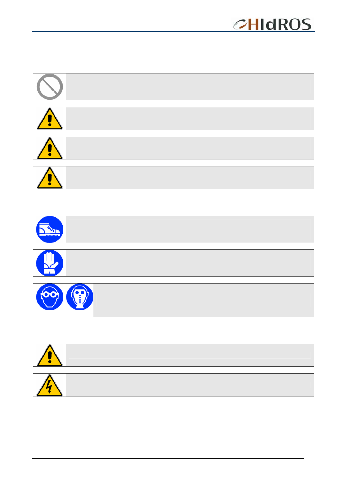
It’s strictly forbidden to remove and/or camper with any safety device.
Any routine or not-routine maintenance operation shall be carried out when the equipment has been shut
down, disconnected from electric and pneumatic power source and after its pneumatic system has been
discharged.
Do not put your hands or insert screwdrivers, spanners or other tools into moving parts of the equipment.
The equipment supervisor and the maintenance man must receive training suitable for the performance of
their tasks in safety
Operators must know how to use personal protective devices and must know the accident-prevention
guidelines contained in national and international laws and norms.
SRH Swimming Pools Dehumidifiers
MTSRHGB 8 REV.072008
WORKERS’ HEALTH AND SAFETY
The European Community has emanated some Directives about worker’s safety and health which the employers have to respect
and make the others respect. For the detailed list, see the CE declaration enclosed.
Do not tamper with or replace parts of the equipment without the specific consent of the manufacturer.
The manufacturer shall have no responsibility whatsoever in case of unauthorised operations.
Using components, expendable materials or spare parts that do not correspond to those recommended
by the manufacturer and/or listed in this manual may be dangerous for the operators and/or damage the
equipment
The operator’s workplace must be kept clean, tidy and free from objects that may camper free
movements. Appropriate lighting of the work place shall be provided so as to allow the operator to carry
out the required operations safely. Poor or too strong lighting can cause risks.
Ensure that work places are always adequately ventilated and that aspirators are working, in good
condition and in compliance with the requirements of the laws in force...
PERSONAL PROTECTIVE EQUIPMENT
When operating and maintaining the SRH unit, use the following personal protective equipment.
Equipment: people who make maintenance or work with the unit, must wear an equipment in accordance
with the safety Directives. They must wear accident prevention shoes with anti-slip sole where the paving
is slippery.
Gloves: During the cleanings and the maintenance operations, it’s necessary the use of appropriate
gloves. In case of gas recharge, it’s compulsory the use of appropriate gloves to avoid the risk of
freezing.
Mask and googles: Respiratory protection (mask) and eye protection (goggles) should be
used during cleaning and maintenance operations.
SAFETY SIGNS
The equipment features the following safety signs, which must be complied with:
General hazard
Electric shock hazard

SRH Swimming Pools Dehumidifiers
MTSRHGB 9 REV.072008
TECHNICAL CHARACTERISTICS
SRH dehumidifiers series are highly performances units designed for swimming pool applications where it is necessary to control
humidity and to prevent condensation to guarantee optimal comfort.
Frame
All SRH units are made from hot-galvanised thick sheet metal, painted with polyurethane powder enamel at 180°C to ensure the
best resistance against the atmospheric agents. The frame is self-supporting with removable panels. All screws and rivets are in
stainless steel. The colour of the units is RAL 7035
Refrigerant circuit
The refrigerant gas used in these units is R407C. The refrigerant circuit is made by using international primary brands components
and according to ISO 97/23 concerning welding procedures. All units are supplied with two circuits, each refrigerant circuit is totally
independent from the other. Any incorrect operation of one circuit does not influence the other circuit. The refrigerant circuit includes:
SRH liquid line manual shut-off valve, sight glass, filter drier, thermal expansion valve with external equalizer, Schrader valves
form maintenance and control, pressure safety device (according to PED regulation).
SRH/WZ these versions are supplied with one refrigerant circuit identical to the SRH version, the second circuit includes: one way
valves, solenoid valves, liquid receiver, water heat recovery, liquid line shut-off valve, sight glass, filter drier, thermal expansion valve
with externalequalizer, Schrader valves formaintenance andcontrol,pressuresafety device.
Compressors
The compressors are scroll type with crankase heater and thermal overload protection by a klixon embedded in the motor winding.
The compressors are mounted on rubber vibration dampers and they can be supplied wih sound attenuation jacket to reduce the
noise emission (option). The compressor crankcase heater is always powered when the unit is in stand-by. The inspection on the
compressors is possible only through the unit front panel.
Condensers and evaporators
Condensers and evaporators are made of copper pipes and aluminium fins. All evaporators are painted with epoxy powders to
prevent corrosion problem due to their use in aggressive environments.The diameter of the copper pipes is 3/8” and the thickness of
the aluminium fins is 0,1 mm. The tubes are mechanically expanded into the aluminium fins to improve the heat exchange factor.
The geometry of these heat exchangers guarantees a low air side pressure drop and then the use of low rotation (and low noise
emission) fans. All units are supplied, standard, with a Stainless steel drip tray and all evaporators are supplied with a temperature
sensor used as automatic defrost probe.
Heat recovery
It is supplied on the SRH/WZ, factory mounted, it is composed by a plate heat exchanger in molibdenum alloy, suitable for operation
with chlorine water; the heat recovery is designed to reject on water about 50% of the total thermal load generated by the unit. When
the heat recovery is activated, the supply air temperature of the unit is, basically, the same of the return air.
Fans
The fans are made of galvanized steel, centrifugal type, double inlet with forward curved blades. They are statically and dynamically
balanced and supplied complete of the safety fan guard according to EN 294. They are mounted on the unit frame by interposition of
rubber vibration dampers. The electric motors are 4 poles (about 1500 rpm), three-phase power supply. The motors are connected to
the fans by pulleys and belts. The protection class of the motors is IP 54.
Air Filter
Supplied as standard with the unit, it is made of G3 class sysnthetic fibre filtering media (efficiency 85% by weight), 48 mm
thickness.
Electric enclosure
The electric switch board is made according to electromagnetic compatibility norms CEE 73/23 and 89/336. The accessibility to the
board is possible after removing the front panel of the unit and the OFF positioning of the main switch. The moisture protection
degree is IP55. In all SRH units are installed, standard, the compressors sequence relay who disables the operation of the
compressor in case the power supply phase sequence is not the correct one (scroll compressors in fact, can be damaged if they
rotate reverse wise). The following components are also standard installed: main switch, magnetic-thermal switches (as a protection
fans and compressors), control circuit automatic breakers, compressor contactors, fan contactors. The terminal board is supplied
with voltage free contacts for remote ON-OFF and general alarm.

SRH Swimming Pools Dehumidifiers
MTSRHGB 10 REV.072008
Microprocessors
All SRH units can be supplied with 2 kind of controls:
Basic control; it manages the following features: antifreeze protection, compressor timing, compressor automatic
starting sequence, defrost cycle, alarm reset, potential free contact for remote general alarm,
Advanced control; in addition to the basic control it manages a wider range of features as: setting the priority operation
mode (SRH/WZ only), managing of the main and the secondary set points, display of the alarms with
historical list, time band operation, integration with hot water coil and modulating valve. Upon request
the advanced control can be connected to a BMS system for the remote control and management. The
technical department is available to study, together with the customer, different solutions using
MODBUS; LONWORKS; BACNET or TREND protocols.
Electronic probe temperature-humidity
This sensor is supplied standard on the SRH/WZ versions supplied with advanced control.
It can be installed either in the room or in the return duct (to be specified before order) and allow the operation of the unit in the
following modes:
•Dehumidification,
•Heating ( by hot water coil),
•Dehumidification + heating,
•Dehumidification + heat recovery.
Control and protection devices
All units are supplied with the following control and protection devices: antifreeze protection sensor, high pressure switch with
manual reset, low pressure switch with automatic reset, high pressure safety valve, compressor thermal overload protection, fans
thermal overload protection.
Testing
All units are totally assembled and charged with refrigerant R407c. They are completely tested before the expedition. All units are in
accordance to the European Directives and they are provided of CE branding and relative conformity certificate.
OTHER VERSIONS
SRH/WZ Unit with heat recovery;
The unit is designed to have one refrigerant circuit condensed by air, the other one condensed both by water and air. If the unit is
supplied with the advanced control panel it is possible to set operation priorities (air or water).
In the SRH/WZ versions the heat recovery is designed to reject on the water about 50% of the total thermal load generated by the
unit. When the heat recovery is activated, the supply air temperature of the unit is, basically, the same of the return air, so,in this
case, the dehumidification is performed without air temperature increase. This operation mode is suitable during intermediate
seasons when the humidity in the swimming pool has to be controlled but also the room air temperature overheating has to be
avoided.
Low noise version (LS)
The low noise version LS is supplied with compressors jacket and complete acoustic insulation of the compressor vane with high
density sound absorbtion material.
ACCESSORIES
•Basic control panel.
•Advanced control panel.
•Hot water coil.
•3 way ON/OFF valve kit to be connected to the hot water coil.
•3 way modulating valve to be connected to the hot water coil.
•Low noise version.
•High static pressure centrifugal fan.
•Horizontalair discharge.
•Pressure gauges.
•Air filter with frame for ducted installation.
SRH Swimming Pools Dehumidifiers
MTSRHGB 11 REV.072008
SWIMMING POOL DEHUMIDIFIERS
SRH
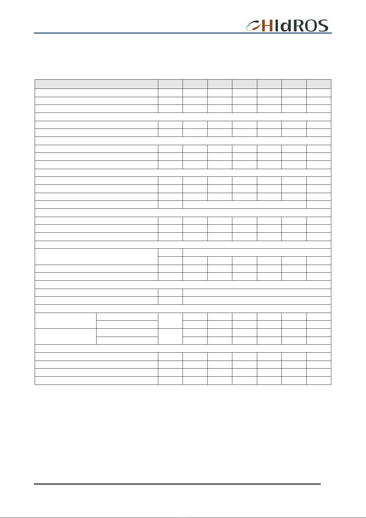
TECHNICAL DATA
Mod. 1100 1300 1500 1800 2200 3000
Refrigerant R407C R407C R407C R407C R407C R407C
Dehumidification capacity (1) l/24h 1130 1280 1490 1880 2310 3050
Compressor input power (1) Kw 14,1 16,5 19,3 23,6 27,6 37
Partial heat recovery (3) kW 19 24 25 32 40 50
Water flow l/h 3280 4200 4300 5500 6900 8600
Hot water coil (4) kW 72 75 94 110 125 155
Water flow l/h 6230 6400 7750 9580 10450 12960
Pressure drops kPa 18 26 16 12 19 22
Nominal input current (1) A 30,8 34,4 36,8 41,2 51,2 62,2
Peak current (1) A 119 146,8 142,8 197,2 233,4 269,8
Maximum input current (2) A 37,8 43,8 47,4 57,8 68,2 87,5
Power supply V/Ph/Hz 400/3+N/50
Air flow m3/h 9500 10500 13000 15000 17000 26000
Fans n° 2 2 2 2 2 3
Available static pressure Pa 250 250 250 250 250 250
tipo SCROLL
Compressor n° 2 2 2 2 2 2
Refrigerant circuits n° 2 2 2 2 2 2
Capacity steps 2 2 2 2 2 2
Temperature range °C 10 – 36
Humidity range % 30 – 99
Standard version 79 80 82 82 83 84
Sound power level (5) (LS) Low noise version dB(A) 77 78 80 80 81 82
Standard version 71 72 74 74 75 76
Sound pressure level (6) (LS) Low noise version dB(A) 69 70 72 72 73 74
standard Unit lenght mm 1870 1870 2608 2608 2608 3608
standard unit depth mm 850 850 1105 1105 1105 1105
standard unit height mm 1270 1270 1566 1566 1566 1566
weight Kg 640 710 770 830 940 1290
(1) Referred to: external temp 30 °C relative humidity 80%
(2) Referred to external temp. 35 °C relative humidity 80%
(3) Referred to water temp. in-out 25/30 °C, room temperature 30°C
(4) Referred to room temp. 32 °C water temp. in-out 80-70 °C
(5) Sound power level according to ISO 3746.
(6) Sound pressure level measured at 1 mt from the unit in free field conditions direction factor Q=2 according to ISO 3746.

SRH Swimming Pools Dehumidifiers
MTSRHGB 12 REV.072008
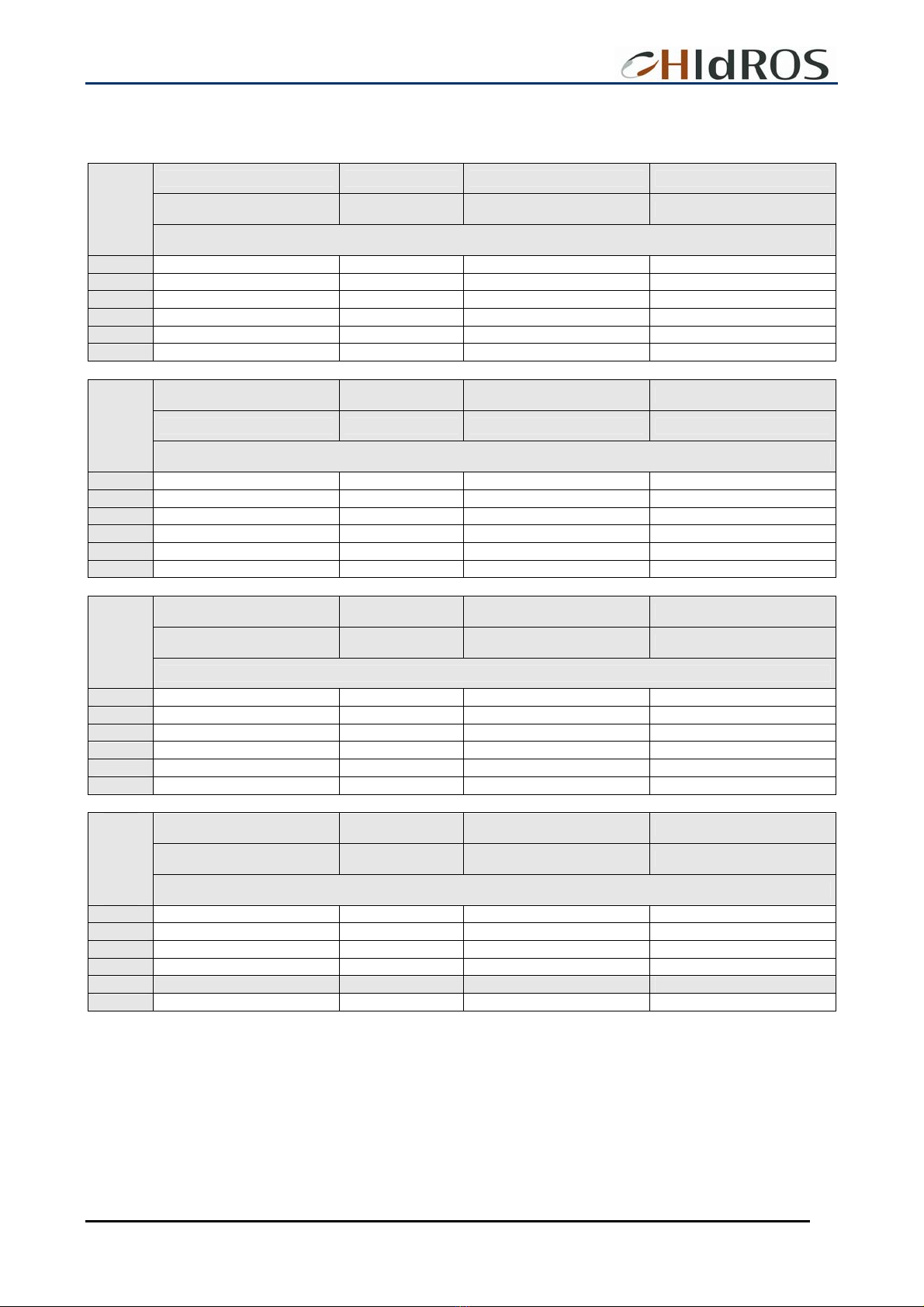
SRH 1100
PERFORMANCES DATA
Dehumidification capacity Input power Air temperature increase Thermal load in the room
[l/24h] [kW] [°C] [kW]
External
temperature
Relative humidity 50%
10°C 148,3 9,4 3,6 12,6
15°C 203,1 10,4 4,1 14,4
20°C 294,4 11,6 4,9 16,9
25°C 421,4 13,1 6,0 20,2
30°C 542,6 14,8 7,0 23,7
35°C 648,4 16,3 8,0 26,7
Dehumidification capacity Input power Air temperature increase Thermal load in the room
[l/24h] [kW] [°C] [kW]
External
temperature
Relative humidity 60%
10°C 206,6 9,5 3,9 13,6
15°C 300,5 10,6 4,7 16,0
20°C 412,4 11,8 5,5 18,9
25°C 577,1 13,3 6,8 22,8
30°C 739,0 15,0 8,0 26,8
35°C 871,7 16,6 9,1 30,3
Dehumidification capacity Input power Air temperature increase Thermal load in the room
[l/24h] [kW] [°C] [kW]
External
temperature
Relative humidity 70%
10°C 265,9 9,8 4,3 14,7
15°C 394,2 11,0 5,2 17,8
20°C 549,1 12,2 6,3 21,2
25°C 724,0 13,7 7,5 25,3
30°C 923,1 15,5 9,0 29,9
35°C 1045,6 17,1 10,0 33,3
Dehumidification capacity Input power Air temperature increase Thermal load in the room
[l/24h] [kW] [°C] [kW]
External
temperature
Relative humidity 80%
10°C 344,6 10,0 4,7 16,1
15°C 493,9 11,1 5,7 19,4
20°C 685,6 12,4 7,0 23,4
25°C 885,7 14,0 8,4 27,9
30°C 1128,2 15,7 10,0 33,1
35°C 1260,9 17,4 11,1 36,7
NOTE: Shadowed fields refer to nominal conditions capacity.

SRH Swimming Pools Dehumidifiers
MTSRHGB 13 REV.072008
SRH 1300
PERFORMANCES DATA
Dehumidification capacity Input power Air temperature increase Thermal load in the room
[l/24h] [kW] [°C] [kW]
External
temperature
Relative humidity 50%
10°C 185,4 10,1 3,6 13,9
15°C 247,7 10,7 4,0 15,4
20°C 351,8 11,7 4,7 17,9
25°C 497,8 13,1 5,7 21,4
30°C 640,2 14,7 6,8 25,0
35°C 784,7 16,5 7,8 28,9
Dehumidification capacity Input power Air temperature increase Thermal load in the room
[l/24h] [kW] [°C] [kW]
External
temperature
Relative humidity 60%
10°C 255,2 10,1 3,9 14,9
15°C 360,3 10,7 4,5 17,0
20°C 485,2 11,7 5,3 19,8
25°C 672,4 13,1 6,4 23,9
30°C 861,4 14,7 7,7 28,2
35°C 1042,9 16,5 8,9 32,6
Dehumidification capacity Input power Air temperature increase Thermal load in the room
[l/24h] [kW] [°C] [kW]
External
temperature
Relative humidity 70%
10°C 327,1 10,3 4,2 16,1
15°C 468,3 11,0 5,0 18,8
20°C 641,1 12,0 6,0 22,3
25°C 839,3 13,4 7,2 26,6
30°C 1073,4 15,0 8,6 31,6
35°C 1250,6 16,9 9,9 36,0
Dehumidification capacity Input power Air temperature increase Thermal load in the room
[l/24h] [kW] [°C] [kW]
External
temperature
Relative humidity 80%
10°C 418,9 10,3 4,6 17,4
15°C 580,6 11,0 5,5 20,4
20°C 789,2 12,0 6,6 24,4
25°C 1013,9 13,4 7,9 29,1
30°C 1297,5 15,0 9,5 34,8
35°C 1492,3 16,9 10,8 39,5
NOTE: Shadowed fields refer to nominal conditions capacity.
SRH Swimming Pools Dehumidifiers
MTSRHGB 14 REV.072008
SRH 1500
PERFORMANCES DATA
Dehumidification capacity Input power Air temperature increase Thermal load in the room
[l/24h] [kW] [°C] [kW]
External
temperature
Relative humidity 50%
10°C 204,4 11,8 3,4 16,3
15°C 276,3 13,1 3,9 18,6
20°C 395,9 14,7 4,7 21,9
25°C 561,1 16,7 5,7 26,3
30°C 717,0 19,0 6,7 30,9
35°C 855,7 21,1 7,6 34,9
Dehumidification capacity Input power Air temperature increase Thermal load in the room
[l/24h] [kW] [°C] [kW]
External
temperature
Relative humidity 60%
10°C 283,6 12,1 3,7 17,7
15°C 406,7 13,5 4,4 20,8
20°C 552,1 15,1 5,3 24,5
25°C 765,5 17,1 6,4 29,6
30°C 973,0 19,4 7,6 34,9
35°C 1146,5 21,5 8,7 39,5
Dehumidification capacity Input power Air temperature increase Thermal load in the room
[l/24h] [kW] [°C] [kW]
External
temperature
Relative humidity 70%
10°C 363,9 12,4 4,0 19,2
15°C 531,3 14,0 4,9 23,1
20°C 732,6 15,6 6,0 27,6
25°C 957,5 17,6 7,2 32,9
30°C 1212,5 20,0 8,6 39,0
35°C 1372,3 22,2 9,6 43,5
Dehumidification capacity Input power Air temperature increase Thermal load in the room
[l/24h] [kW] [°C] [kW]
External
temperature
Relative humidity 80%
10°C 469,8 12,7 4,4 20,9
15°C 663,7 14,2 5,4 25,2
20°C 910,9 15,9 6,6 30,5
25°C 1166,9 18,0 7,9 36,3
30°C 1476,9 20,4 9,5 43,2
35°C 1649,5 22,6 10,6 47,9
NOTE: Shadowed fields refer to nominal conditions capacity.

SRH Swimming Pools Dehumidifiers
MTSRHGB 15 REV.072008
SRH 1800
PERFORMANCES DATA
Dehumidification capacity Input power Air temperature increase Thermal load in the room
[l/24h] [kW] [°C] [kW]
External
temperature
Relative humidity 50%
10°C 263,9 15,5 7,0 21,5
15°C 356,0 17,2 8,1 24,5
20°C 508,8 19,3 9,6 28,8
25°C 719,3 21,9 11,7 34,5
30°C 916,5 24,9 13,8 40,3
35°C 1094,7 27,6 15,7 45,6
Dehumidification capacity Input power Air temperature increase Thermal load in the room
[l/24h] [kW] [°C] [kW]
External
temperature
Relative humidity 60%
10°C 365,3 15,8 7,6 23,2
15°C 522,3 17,6 9,1 27,4
20°C 707,3 19,8 10,8 32,1
25°C 978,3 22,4 13,2 38,7
30°C 1240,1 25,5 15,7 45,5
35°C 1462,6 28,2 17,8 51,5
Dehumidification capacity Input power Air temperature increase Thermal load in the room
[l/24h] [kW] [°C] [kW]
External
temperature
Relative humidity 70%
10°C 468,8 16,2 8,3 25,2
15°C 681,3 18,3 10,2 30,3
20°C 937,1 20,4 12,3 36,1
25°C 1221,8 23,2 14,7 43,0
30°C 1543,2 26,3 17,6 50,7
35°C 1748,0 29,1 19,6 56,5
Dehumidification capacity Input power Air temperature increase Thermal load in the room
[l/24h] [kW] [°C] [kW]
External
temperature
Relative humidity 80%
10°C 604,0 16,5 9,1 27,4
15°C 849,3 18,6 11,1 33,0
20°C 1161,7 20,9 13,6 39,8
25°C 1484,9 23,6 16,3 47,3
30°C 1874,7 26,8 19,5 56,0
35°C 2095,6 29,7 21,7 62,1
NOTE: Shadowed fields refer to nominal conditions capacity li.

SRH Swimming Pools Dehumidifiers
MTSRHGB 16 REV.072008
SRH 2200
PERFORMANCES DATA
Dehumidification capacity Input power Air temperature increase Thermal load in the room
[l/24h] [kW] [°C] [kW]
External
temperature
Relative humidity 50%
10°C 336,2 18,4 4,0 24,2
15°C 447,3 19,6 4,5 26,9
20°C 632,8 21,4 5,3 31,4
25°C 892,0 24,0 6,4 37,6
30°C 1143,4 27,0 7,5 44,1
35°C 1398,4 30,5 8,7 51,1
Dehumidification capacity Input power Air temperature increase Thermal load in the room
[l/24h] [kW] [°C] [kW]
External
temperature
Relative humidity 60%
10°C 462,0 18,3 4,3 25,9
15°C 649,4 19,5 5,0 29,7
20°C 871,5 21,4 5,9 34,6
25°C 1203,7 24,0 7,1 41,9
30°C 1537,0 27,0 8,5 49,6
35°C 1857,2 30,4 9,8 57,5
Dehumidification capacity Input power Air temperature increase Thermal load in the room
[l/24h] [kW] [°C] [kW]
External
temperature
Relative humidity 70%
10°C 591,6 18,8 4,7 28,1
15°C 843,0 20,0 5,5 32,9
20°C 1150,3 21,8 6,6 39,0
25°C 1500,8 24,5 7,9 46,6
30°C 1913,7 27,6 9,5 55,5
35°C 2225,3 31,2 10,9 63,4
Dehumidification capacity Input power Air temperature increase Thermal load in the room
[l/24h] [kW] [°C] [kW]
External
temperature
Relative humidity 80%
10°C 756,8 18,7 5,1 30,4
15°C 1044,2 19,9 6,0 35,6
20°C 1414,3 21,8 7,3 42,7
25°C 1811,4 24,5 8,7 50,9
30°C 2311,5 27,6 10,5 61,1
35°C 2653,7 31,2 11,9 69,4
NOTE: Shadowed fields refer to nominal conditions capacity.

SRH Swimming Pools Dehumidifiers
MTSRHGB 17 REV.072008
SRH 3000
PERFORMANCES DATA
Dehumidification capacity Input power Air temperature increase Thermal load in the room
[l/24h] [kW] [°C] [kW]
Temperatura
ambiente
Relative humidity 50%
10°C 449,7 23,6 3,4 30,5
15°C 597,1 25,4 3,8 34,2
20°C 841,8 28,0 4,4 39,9
25°C 1180,6 31,6 5,3 48,0
30°C 1504,4 35,8 6,3 56,3
35°C 1822,9 40,5 7,3 65,1
Dehumidification capacity Input power Air temperature increase Thermal load in the room
[l/24h] [kW] [°C] [kW]
External
temperature
Relative humidity 60%
10°C 618,4 23,7 3,6 32,7
15°C 868,0 25,5 4,2 37,8
20°C 1161,0 28,1 4,9 44,2
25°C 1595,6 31,7 6,0 53,4
30°C 2025,7 35,9 7,1 63,2
35°C 2426,0 40,6 8,2 73,0
Dehumidification capacity Input power Air temperature increase Thermal load in the room
[l/24h] [kW] [°C] [kW]
External
temperature
Relative humidity 70%
10°C 791,2 24,2 3,9 35,5
15°C 1126,1 26,1 4,6 41,8
20°C 1531,6 28,8 5,5 49,7
25°C 1988,2 32,6 6,6 59,3
30°C 2520,4 36,9 7,9 70,5
35°C 2904,5 41,7 9,0 80,3
Dehumidification capacity Input power Air temperature increase Thermal load in the room
[l/24h] [kW] [°C] [kW]
External
temperature
Relative humidity 80%
10°C 1012,9 24,3 4,3 38,5
15°C 1396,0 26,2 5,0 45,3
20°C 1885,6 28,9 6,1 54,3
25°C 2403,0 32,7 7,3 64,8
30°C 3049,0 37,0 8,7 77,5
35°C 3470,1 41,8 9,9 87,7
NOTE: Shadowed fields refer to nominal conditions capacity.

SRH Swimming Pools Dehumidifiers
MTSRHGB 18 REV.072008
UNIT CONFIGURATIONS
SRH units are available in 2 configurations:
SRH: The unit is designed to have both refrigerant circuits condensed by air; in this configuration the unit will always
transfer the thermal load (electric input power + condensation load) to the air having so, the temperature
increase reported in the performance data (see previous pages).
SRH/WZ: The unit is designed to have one refrigerant circuit condensed by air, the other one condensed either by water
and air. If the unit is supplied with the advanced control panel it is possible to set the operation priorities:
Priority air temperature: When the priority is the air temperature the unit operates in order to keep the air
temperature below the required set point; in case the air temperature tends to increase, it is activated the partial
heat recovery who transfers to the water part of the thermal load of the unit. When the partial heat recovery is
activated the supply air is at the same temperature of the return air.
Priority water temperature When the priority is the water temperature the unit operates in order to keep the
water temperature below the required set point; in case the water temperature tends to increase, it is activated
the air condenser who transfers to the air part of the thermal load of the unit. When the partial heat recovery is
activated the air discharge temperature is neutral.
Both SRH versions can be supplied either with basic control panel or advanced control panel.
Nevertheless, the priority operation modes described above are available using the advanced control
panel only.
SRH/WZ units supplied with basic control panel, are only available in “air temperature priority” .
SRH SRH/WZ
LEGEND
A Compressor F Evaporator
B Expansion valve G Air filter
C Solenoid valve H Condenser
D Heat recovery (option) I Hot water coil (option)
E One way valve L Supply fan
SRH Swimming Pools Dehumidifiers
MTSRHGB 19 REV.072008
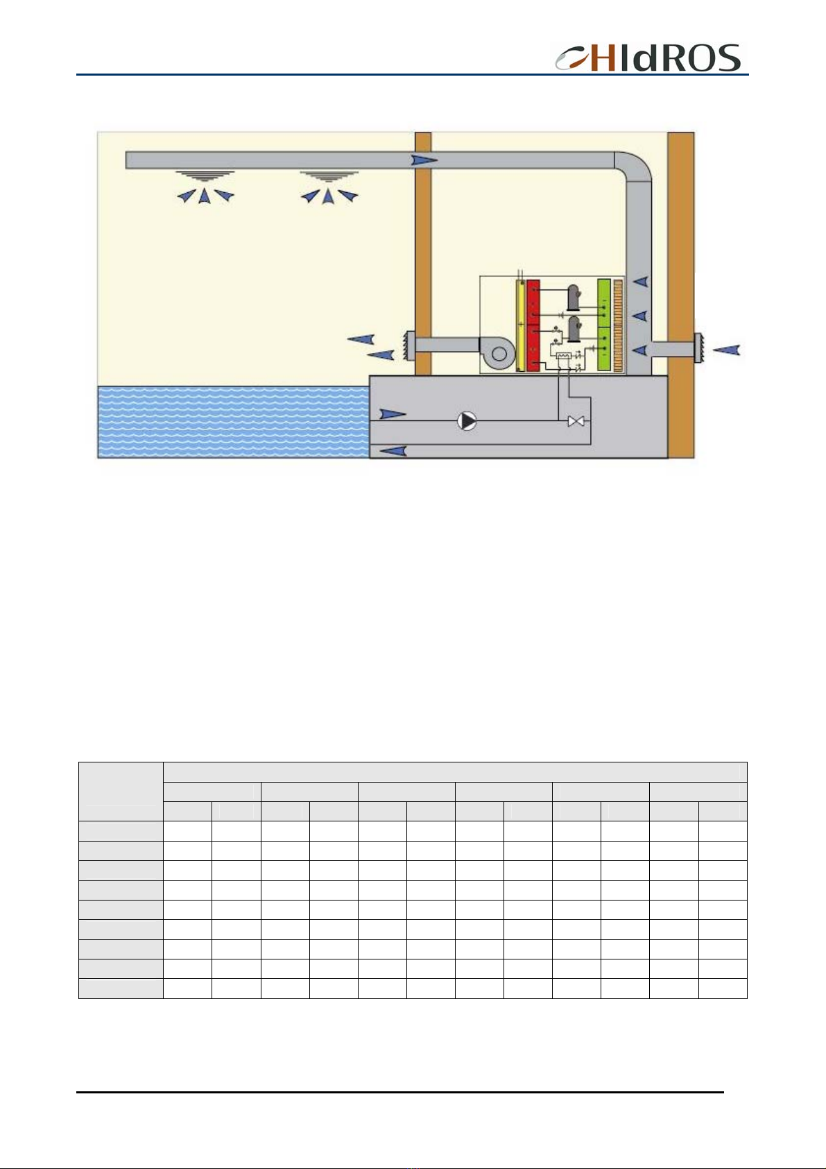
TYPICAL INSTALLATION
The picture above shows a typical installation of the SRH units;
Normally, the unit is installed in the technical room and ducted on both sides (supply and return).
In many installations it is installed a fresh air duct designed for 15-20% airflow.
Clearly, in this application also an exhaust fan has to be installed in order to avoid over pressure in the swimming pool.
The water valve present in the heat recovery hydraulic circuit has to be set in order to guarantee the nominal water flow in the heat
recovery.
The table reported here below, calculates the quantity of evaporated water for m2of pool. It’s possible to estimate approximately the
total pool evaporation multiplying this value for the surface of the pool. The values reported are in kg/h and are to be intended as
pure indicative. In case of use in ambient with hydromassage, it’s advisable to multiply the values obtained for 2,5-3.
Room temperature / relative humidity
27°C 28°C 29°C 30°C 31°C 32°C
Water
temperature
50% 60% 50% 60% 50% 60% 50% 60% 50% 60% 50% 60%
22°C 0,108 0,057 0,092 0,041 0,075 0,023 0,059 0,008 --- --- --- ---
23°C 0,134 0,080 0,117 0,062 0,099 0,044 0,083 0,026 0,065 --- --- ---
24°C 0,161 0,105 0,144 0,086 0,126 0,068 0,108 0,048 0,090 0,029 --- ---
25°C 0,191 0,134 0,173 0,114 0,155 0,093 0,135 0,074 0,117 0,053 0,098 ---
26°C 0,222 0,164 0,204 0,143 0,186 0,122 0,167 0,101 0,147 0,080 0,126 0,057
27°C 0,258 0,197 0,239 0,176 0,219 0,155 0,200 0,132 0,180 0,110 0,158 0,086
28°C 0,296 0,233 0,276 0,212 0,257 0,189 0,236 0,165 0,215 0,143 0,194 0,117
29°C 0,336 0,272 0,317 0,249 0,296 0,227 0,275 0,203 0,254 0,179 0,231 0,153
30°C 0,378 0,314 0,359 0,291 0,339 0,267 0,317 0,243 0,296 0,218 0,272 0,191
Values are intended as kg/h.
Fresh air
(max.20%)
Supply air
Return air
Setting
valve
Swimmin
g
p
ool water
p
um
p
SRH unit

SRH Swimming Pools Dehumidifiers
MTSRHGB 20 REV.072008
REFRIGERANT CIRCUITS
SRH
M
EV
FL
EXT
MFC
SHP
SLP
∅S
∅L
∅D
CH
VSH
IV SV
Unità/Model Taglia/Size
1500-1800-2200
∅D∅L∅S
18
35 18
3000 28 42 22
SRH SRF 1100-1300
22
28 16
SRH SRF
SRH SRF
M
MFC
CND
V3W
CH Charging plug MFC Centrifugal fan
CND Condenser SHP High pressureswitch
EV Evaporator SLP Low pressure switch
EXT Thermostatic valve VSH High pressuresafety valve
FL Liquid line filter IV Sight glass
MC Compressor SV Manual valve
V3W Water valve (Option)
Other manuals for SRH Series
1
Other HIdRos Dehumidifier manuals

HIdRos
HIdRos GH Series User manual

HIdRos
HIdRos HHA Series User manual

HIdRos
HIdRos SDA Series User manual

HIdRos
HIdRos GHE Series User manual

HIdRos
HIdRos ITMBT Series User manual

HIdRos
HIdRos HDA Series User manual

HIdRos
HIdRos SMA Series User manual

HIdRos
HIdRos SHH Series User manual

HIdRos
HIdRos HMA/Z Series User manual

HIdRos
HIdRos HMA BT Series User manual


