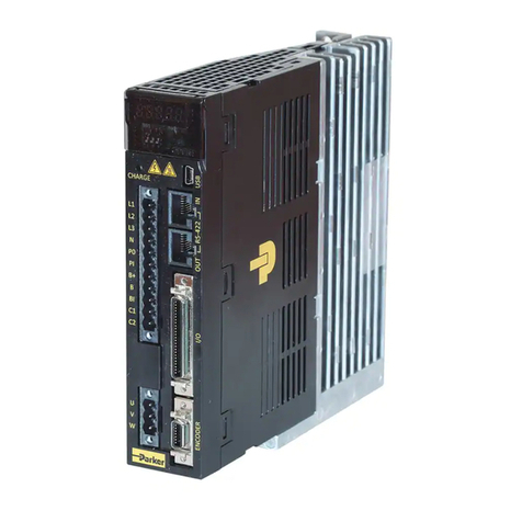
Higen FDA6000C Series User manual

OPERATION MANUAL
AC Servo Drive
FDA6000C Series
Ver 1.2 (Soft. Ver. 6.06 ~)
FDA6000C Series
ServoDriveUser Manual

< CAUTION >
1. Check Motor ID certainly. ( P1-01 )
2. Check Drive Amp-Type certainly. ( P1-10 )
Drive 6001C 6002C 6004C 6005C 6010C 6012C 6015C 6020C 6030C 6045C 6075C 6110C 6150C
Amp
Type 0 1 2 5 6 7 11 12 13 14 15 16 17
3. Check Encoder Pulse certainly. ( P1-12 )
Example)
Encoder Type
4. Operate servo system after autotuning is off. ( P2-23 )
5. Avoid impacting to the Motor in connecting. Especially, avoid
impacting to the Encoder in connecting coupling to the Motor shaft or
operating.
6. Recommended specifications in Encoder wiring.
Check Encoder Type and use authorized shield cable.
Encoder Type Reference Page
Incremental Encoder 3-16
AbsoluteEncoder 3-18
7. Treatment of the servo motor attached holding brake .
: The brake built in the servo motor is a normal closed type brake.
Which is used only to hold and can not be used for braking. Use the
holding brake only to hold a stopped servo motor.
Symbol Pulse Type
A 2000
B 2500
C 3000
D 5000
E 6000
F 2048
Incremental
15 wires
G 2048 Absolute 11/13bit
FMALN09-AB00

Contents
1. Checking and Handling
1.1 Handling ------------------------------------------------------------------- 1-1
1.2 Caution during Use ----------------------------------------------------------- 1-2
1.3 Installation ------------------------------------------------------------------ 1-3
1.4 Order Specifications ---------------------------------------------------------- 1-7
2. Ratings and Specifications
2.1 Ratings and specifications for AC servo drive FDA6000C series ---- 2-1
2.2 AC Servo Motor Ratings and Specifications --------------------------- 2-2
3. Wiring and Signals
3.1 Power parts wiring ----------------------------------------------------------- 3-2
3.2 Connection and signal-form of input/output ------------------------------ 3-9
3.3 CN1 Wiring and Signal -------------------------------------------------------- 3-12
3.4 CN2 Wiring and Signal -------------------------------------------------------- 3-17
4. Digital Loader Operation
4.1 Handling and Menu system ------------------------------------------------- 4-2
4.2 Changing Parameters ---------------------------------------------------------- 4-3
5. Parameter Setting
5.1 Parameter Summary ---------------------------------------------------------- 5-1
5.2 Motor and System Parameter (Motor Parameter: P1--) --------------- 5-7
5.3 Control Parameter (Control Mode: P2--) --------------------------------- 5-10
5.4 Speed control parameter (Speed Mode : P3--) --------------------------- 5-16
5.5 Position control parameter (Position Mode: P4--) ---------------------- 5-18
5.6 Position Command Parameter(POS Command Mode : P5--) -------- 5-20
5.7 Jog/Original Mode Parameter (Jog/Origin Mode : P6-- ) ------------- 5-22
5.8 Mechanical Parameter (Mechanical Mode : P7--) ---------------------- 5-23
5.9 Operational Mode Parameter (Operation Mode : P8--) --------------- 5-25
5.10 Description of servo status (Status Window: St--) ---------------------- 5-31
5.11 Alarm Status Display (Alarm Status : ALS--) ------------------------- 5-33

Contents
6. Operation Mode and How to use
6.1 An important point check and set items, when operation --------------- 6-1
6.2 How to operate absolute position -------------------------------------------- 6-3
6.3 How to use relative position operation. ------------------------------------ 6-5
6.4 How to use sequential operation. -------------------------------------------- 6-6
6.5 Setting of position, input and output ---------------------------------------- 6-8
6.6 Origin Operation -------------------------------------------------------------- 6-9
6.7 How to JOG operation --------------------------------------------------------- 6-11
6.8 How to use Monitor ------------------------------------------------------------ 6-12
7. Maintenance and Inspection
7.1 Caution --------------------------------------------------------------------------- 7-1
7.2 Inspection Items ---------------------------------------------------------------- 7-1
7.3 Replacing Parts ----------------------------------------------------------------- 7-2
7.4 Maintenance --------------------------------------------------------------------- 7-3
8. Troubleshooting
8.1 Servo Motor --------------------------------------------------------------------- 8-1
8.2 Servo drive --------------------------------------------------------------------- 8-2
9. External View
9.1 External Dimensions of AC Servo Drive -------------------------------- 9-1
9.2 External Dimensions of AC Servo Motor --------------------------------- 9-2
10. Specifications of options
10.1 AC servo motor cable specifications ---------------------------------------- 10-1
10.2 AC servo drive ----------------------------------------------------------------- 10-3
[Appendix] Revision History

Chapter 1. Checking and Handling
1-1
1. Checking and Handling
1.1 Handling (Connection of main circuit and motor)
Thank you for purchasing HIGEN AC Servo Drive. Incorrect handling of the drive may lead to
unsatisfactory operation or, in some cases, to the rapid reduction of its life, or damage to the servo
system. Handle and operate the drive according to the instructions given in this manual.

Chapter 1. Checking and Handling
1-2
1.2 Caution during Use
Improper handling of the drive may lead to unexpected accident or damage. The following are
important points in drive operation.
1.2.1 Handling
yAvoid impact to the encoder, the motor detector.
Striking the shaft with a hammer or dropping the motor may cause unexpected damage.
yDo not connect commercial power supply (AC 220V) directly to the motor.
Direct connection induces flow of over current leading to demagnetize the magnet in motor.
Always use motor with specified servo drive.
1.2.2 Wiring
yConnect the drive and the motor earth terminals in the direction of the drive, and ground the
terminals at the shortest distance at a time. To prevent both electric shock and improper
operation, use class-3 earth (Less than 100 Ω).
yAlways match the U, V, W and FG terminals of the motor with those of the drive. You cannot
change the direction of rotation by changing 2 wires the same as in the case of widely used
general motors.
yConnecting commercial power supply to the U, V ,W and FG terminals of the drive may cause
damage.
(Apply 200V power supply to R, S and T terminals)
Use a transformer in case power supply is other than 200V.
yConnect standard regenerative resistor to the P and B terminals of the drive.
Higen
AC SERVO MOTOR
made in korea

Chapter 1. Checking and Handling
1-3
1.2.3 Operation
yUse the magnetic brake of the motor only for emergency and maintenance (preservation).
The brake is designed for maintenance (preservation) during power outage. If used to reduce
the speed, the brake wears out quickly.
yInstall brakes and magnetic contactors on power supply terminals R, S and T.
In case an error occurs or abnormal current flows, shut off the circuit to prevent secondary fire.
1.2.4 Maintenance and inspection
y"High voltage" still remains inside the drive for a while even after power supply is shut off.
(Danger!)
To prevent electric-shock, carry out wiring work or inspection at least l0 minutes after the power
is cut off and the charge lamp is turned off.
yThe regenerative resistor and the servo motor remain hot for a while after power is turned off.
Touching them may cause burns.
yMegger test on the drive may cause damage to the drive. Do not perform megger test.
yDo not disassemble the motor detector. never remove the cover.
1.3 Installation
1.3.1 Installation of servo drive
yOperating environment
Ambient temperature 0-50℃(There should be no freezing) Note)
Ambient humidity 90% RH or lower (There should be no vapor)
Note) Inside panel temperature specifications: To ensure maximum operating life and reliability
of the drive, maintain the average panel temperature at 40℃or lower.

Chapter 1. Checking and Handling
1-4
yInstallation direction and intervals
- Install FDA6000C can be seen from the front.
- If the drives are installed in a closed panel, maintain an interval of more than 10 mm
between drives and more than 40 mm between top and bottom. If multiple number of panels
are installed in parallel, about 100 mm space is required on the upper side.
In case of installing fans, avoid heat.
- Regenerative resistor, heating source, away from the drive.
yPrevention of infiltration of outside materials
- Exercise caution when drilling control panels to prevent chips produced by drilling from
getting into the drive.
- Take appropriate measures to prevent oils, water and metal powder from getting into the
drive from openings in the control panels and the fan installed on the ceiling.
- If the drive is used in a place with large amount of toxic gases and dust, protect the drive with
an air purge.
1.3.2 Servo motor installation
yOperating environment
Ambient temperature 0-40℃(There should be no freezing)
Ambient humidity 80% RH or lower (There should be no vapor)
External vibration X, Y = 19.6 ㎨(2G)
yCaution when assembling load system (Prevent impact on shaft)
It is important to accurately match the motor shaft with the shaft center of the connecting
machine. Mismatched shaft center causes vibration, and may cause damage to the bearing. Use
a rubber hammer to install couplings to prevent excessive force from being applied to the shaft
and bearing.
Check 4 places in turn. The difference between maximum and minimum should be 0.03 or lower.
yLoad tolerance on shaft
- Use flexible couplings, and maintain the shaft center deviations within the specified tolerance.
- Use pulleys and sprockets with the allowable load.

Chapter 1. Checking and Handling
1-5
-
MOTOR MODEL RADIAL LOAD AXIAL LOAD
Series Type N Kgf N kgf REFERENCE DIAGRAM
CN01~CN05 196 20 68 7
CN04A~CN10 245 25 98 10
CN09~CN30 686 70 343 35
CN
CN30A~CN50A 1470 150 490 50
KN03~KN07 245 25 98 10
KF06A~KN22 686 70 343 35
KN
KN22A~KN70 1470 150 490 50
TN05~TN17 686 70 343 35
TN20~TN75 1470 150 490 50
TN
TN110~TN150 1764 180 588 60
LN03~LN12 686 70 343 35
LN LN12A~LN55 1470 150 490 50
KF08~KF15 686 70 343 35
KF KF22~KF50 1470 150 490 50
TF05~TF13 686 70 343 35
TF TF20~TF44 1470 150 490 50
LF03~LF09 686 70 343 35
LF LF12~LF30 1470 150 490 50
Radial
Load
A
xial
Load
yAccuracy of attachments
The accuracies of the shaft and attachments of the AC servo motor are shown on the following
table.
Item Accuracy
(T.I.R.) Reference Diagram
Perpendicularity of flange attachment plane and
output shaft (A) 0.04mm
Eccentricity of flange fitting outer diameter (B) 0.04mm
Vibration of shaft end (C) 0.02mm
(Note) T.I.R : Total Indicator Reading

Chapter 1. Checking and Handling
1-6
yImpact resistance
The drive withstands two times of impacts with an acceleration of
10G when up-and-down impacts are applied after setting the motor
shaft horizontally.
However, a precision detector is attached to the end of the shaft on
the opposite side of the load, take caution not to apply impact directly
to this end.
yVibration resistance
The drive withstands a vibration acceleration of 2.0G when
vibration is applied in up and down, left and right, and front
and back directions after setting the motor shaft horizontally.
yVibration grade
The vibration grade of the AC servo motor is V15 at the rated rpm.
yDirection of installation
- Motor can be installed horizontally or at the top or bottom of the shaft.
- Keep the motor cable downward.
- If the motor is installed vertically, install a cable trap so that oils or water do not flow into the
motor.
yCable disconnection
- Take caution not to cause stress or damage to the cables.
- If the motor is used as a mobile motor, use flexible cables.

Chapter 1. Checking and Handling
1-7
1.4 Order Specifications
Prior to installing the product, check the ratings plate to see if the related specifications match with
those of the order.
1.4.1 Servo motor model marking
ACservomotor OilSealtype
Series
Brake installed
Shafttype
Rated output (Watt)
Encoder type
1.4.2 Servo drive model marking
Symbol Item
0 None
1 Oil seal attached
Symbol Item
0 None
1 DC type
2 130 Flange
24V Brake
Symbol Use
CN,CK High-speed, low torque type
KF,KN Medium-speed, standard type
TF,TN Medium-speed, high torque type
LF,LN Low-speed, large torque type
Symbol Item
A Straight(No key)
B Straight(With key)
C Taper & Key
Symbol Rated
output (W) Symbol Rated
output (W)
01 100 16 1600
02 200 20 2000
03 300 22 2200
04 400 30 3000
05 450/500 35 3500
06 550/600 40 4000
07 650 44 4400
08 750/800 50 5000
09 850/900 55 5500
10 1000 75 7500
12 1200 110 11000
13 1300 150 15000
15 1500
Symbol Pulse Type
A 2000
B 2500
C 3000
D 5000
E 6000
F 2048
Incremental
15 lines
G 2048 Absolute 11/13bit
Symbol Encoder type
None Incremental
A Absolute
Symbol Type
None Standard Type
C Position Decision Type
CN Position Decision Type +
Comm. Type
Symbol Power
(Watt) Symbol power
(Watt) Symbol Power
(Watt)
001 100 012 1200 075 7500
002 200 015 1500 110 11000
004 400 020 2000 150 15000
005 500 030 3000
010 1000 045 4500
FMA
FDA 6
AC servo drive
6000 Series
Rated Power
Encoder Type
Type

Chapter 1. Checking and Handling
1-8
1.4.3 AC Servo application table
Drive
Motor Flange Model 6001
C 6002
C 6004
C 6005
C 6010
C 6012
C 6015
C 6020
C 6030
C 6045
C 6075
CN 6110
CN 6150
CN
CKZ5 ◎
40 CK01 ◎
CK02 ◎
CK
Series
3000
/5000
(r/min) 60 CK04
◎
CN01 ◎
CN02
◎
CN03
◎
CN04
◎
60
CN05
◎
CN04A
◎
CN06
◎
CN08
◎
80
CN10
◎
CN09
◎
CN15 ◎
CN22
◎
130
CN30
◎
CN30A
◎
CN50A
◎
CN
Series
3000
/5000
(r/min)
180 CN70
◎
KN03
◎
KN05
◎
KN06
◎
80
KN07
◎
KN06A
◎
KN11
◎
KN16 ◎
130
KN22
◎
KN22A
◎
KN35
◎
KN55 ◎
KN
Series
2000
/3000
(r/min)
180
KN70 ◎
TN05
◎
TN09
◎
TN13 ◎
130
TN17
◎
TN20
◎
TN30
◎◎
TN44 ◎
TN55 ◎
TN
Series
1500
/3000
(r/min) 180
TN75 ◎
TN110
◎
1500/2000
(r/min) 220 TN150
◎

Chapter 1. Checking and Handling
1-9
Drive
Motor Flange Model 6001
C 6002
C 6004
C 6005
C 6010
C 6012
C 6015
C 6020
C 6030
C 6045
C 6075
CN 6110
CN 6150
CN
LN03
◎
LN06
◎
LN09
◎
130
LN12
◎
LN12A ◎
LN20
◎
LN30
◎
LN40 ◎
LN
Series
1000
/2000
(r/min) 180
LN55 ◎
KF08
◎
KF10
◎
130 KF15 ◎
KF22
◎
KF35
◎
KF
Series
2000
/3000
(r/min) 180 KF50 ◎
TF05
◎
TF09
◎
130 TF13 ◎
TF20
◎
TF30
◎
TF
Series
1500
/3000
(r/min) 180 TF44 ◎
LF03
◎
LF06
◎
130 LF09
◎
LF12 ◎
LF20
◎
LF
Series
1000
/2000
(r/min) 180 LF30
◎

Chapter 2. Ratings and Specifications
2-1
2. Ratings and Specifications
2.1 Ratings and specifications for AC servo drive FDA6000C series
Model [FDA-]
Item 6001
C 6002
C 6004
C 6005
C 6010
C 6012
C 6015
C 6020
C 6030
C 6045
C 6075
CN 6110
CN 6150
CN
Power supply voltage
*(note1) 3 phase AC200~230V +10/-15%, 50/60Hz
Input
power
supply Power capacity [kVA] 0.5 0.8 1.3 1.5 2.1 2.5 3.1 4.1 6.0 8.0 12.0 17.6 24
Voltage type 3 phase sine wave drive AC servo motor
Continuous output current [A] 1.25 2.1 3.2 4.2 6.9 9.8 11 16 21 32 49.6 54.5 73.7
Applicable
motor Maximum output
current [A] 3.8 6.3 9.6 12.6 19.2 29 33 48 63 96 119 131 192.5
Detector model Standard : Incremental 2000 [p/rev] 15-wire type
Option : Absolute 2048 [p/rev] 11/13bit
Output signal type Differential Line Driver output
Detector accuracy 1000 ~ 10000 [p/rev] (Not to exceed 400 [kp/sec])
Detector
Detector power supply Not to exceed DC 5[V], 0.3 [A]
Drive system 3-phase voltage type PWM drive ( IPM used )
Position setting Absolute position data(32 points) setting
Command input Select absolute position data(32 points) by input contact
Absolute
Mode System Absolute position command method, short distance discrimination function
Position setting Relative position data(32 points) setting
Command input Select relative position data(32 points) by input contact
Relative
Mode System Relative position command method
Position setting Position data 4 points setting
Run Mode
Specificati
on
Sequence
Mode System Sequence loop operation, select Step/Auto operation
Input frequency 500[kpps]
Pulse Logic Direction + pulse, forward run pulse + reverse run pulse
2-phase pulse (A phase + B phase)
MPG
Input Type Open collector, line driver system
Jog operation Digital Loader/input contact(able to operate contact limit simultaneously)
Origin Rule Be selected by parameter
Speed override function Be set by parameter
Position
control
specificati
ons
Speed accel/decel time Able to set 4 patterns( 8 positions/ 1 pattern)
Protective functions Overcurrent, regenerative overvoltage, overload, motor miswiring, drive overheat,
encoder error, voltage shortage, overspeed and excessive error.
Regenerative resistor Standard separately attached type
Monitor output Speed, torque and position (-4 ∼+4 [V])
Dynamic brake built in
Built-in
functions
Additional function Testing function (jog operation), alarm history, forward and backward run, encoder
signal frequency division output
Option Digital Loader , Power cable, encoder cable, CN1 connector, CN2 connector
Operating ambient
temperature 0-50 [℃]
Ambient humidity Not to exceed 90 [%] (Should be free of dewing)
Storage temperature -20 ~ +80 [℃]
Environme
ntal
specificati
ons Insulating resistance To be greater than DC 500 [V] 10 [MΩ]
Structure Book Type
(Note 1) The model name of the servo drive, which uses absolute encoder, is FDA6000CA.
(Note 2) Single-phase AC 220V can also be used. However, as output may become lower
than the rated value, raise the servo drive capacity by 1 step if possible.

Chapter 2. Ratings and Specifications
2-2
2.2 AC Servo Motor Ratings and Specifications
Motor CKZ5 CK01 CK02 CK04
Model
Spec. Drive 6001C 6001C 6002C 6004C
Flange size ( □) 40 60
Rated output ( W ) 50 100 200 400
( N·m ) 0.16 0.32 0.64 1.27
Rated torque ( kgf·cm ) 1.62 3.25 6.5 13.0
( N·m ) 0.48 0.95 1.92 3.81
Maximum
instantaneous
torque ( kgf·cm ) 4.87 9.74 1.95 39.0
Rated rpm ( r/min ) 3000
Maximum rpm ( r/min ) 5000
( gf·cm·s2) 0.049 0.081 0.246 0.440
Rotor
inertia
( = GD2/4 ) (kg·m2ⅹ10-4) 0.048 0.079 0.241 0.431
Allowable load inertia
Ratio(Versus rotor) 15 times or below
Rated power rate ( kW/s ) 5.3 12.8 16.5 36.8
Standard Incremental 2000
Detector type Option Absolute 11/13bit 2048P/rev
Weight ( kg ) 0.42 0.55 1.0 1.73
■Speed and Torque Characteristics
A : Continuous duty zone & B : Intermittent duty zone
1000 2000 3000 4000 5000
Speed (r/min )
0.1
Torque(N
·
m )
0.5
0.4
0.3
0.2
CKZ5
A
B
1000 2000 3000 4000 5000
Speed (r/min )
0.2
Torque(N
·
m )
0.5
0.8
0.6
0.4
CK01
A
B
1000 2000 3000 4000 5000
Speed (r/min )
0.4
Torque(N
·
m )
2.0
1.6
1.2
0.8
CK02
A
B
1000 2000 3000 4000 5000
Speed (r/min )
0.8
Torque(N
·
m )
4.0
3.2
2.4
1.6
CK04
A
B

Chapter 2. Ratings and Specifications
2-3
Motor CN01 CN02 CN03 CN04 CN05 CN04A CN06 CN08 CN10
Model
Spec. Drive 6001C 6002C 6004C 6005C 6010C
Flange size ( □) 60 80
Rated output ( W ) 100 200 300 400 500 400 600 800 1000
( N·m ) 0.32 0.64 0.96 1.27 1.59 1.27 1.91 2.54 3.18
Rated torque ( kgf·cm ) 3.25 6.5 9.75 13.0 16.2 13.0 19.5 26.0 32.5
( N·m ) 0.96 1.92 2.88 3.81 4.77 3.81 5.3 6.85 9.53
Maximum
instantaneous
torque ( kgf·cm ) 9.75 19.5 29.3 39.0 48.7 39.0 54.5 70.2 97.5
Rated rpm ( r/min ) 3000
Maximum rpm ( r/min ) 5000
( gf·cm·s2) 0.061 0.095 0.126 0.160 0.204 1.1 1.5 1.77 2.11
Rotor
inertia
( = GD2/4 ) (kg·m2ⅹ10-4) 0.06 0.093 0.129 0.163 0.208 1.08 1.47 1.74 2.07
Allowable load inertia
Ratio(Versus rotor) Not exceeding 30 times Not exceeding 20 times
Rated power rate ( kW/s ) 17.0 43.6 73.9 103.5 126.1 15.0 24.8 37.4 49.0
Standard Incremental 2000
Detector type Option Absolute 11/13bit 2048P/rev
Weight (kg) 0.85 1.14 1.43 1.73 2.03 2.1 2.55 3.1 3.7
■Speed and Torque Characteristics
A : Continuous duty zone & B : Intermittent duty zone
1000 2000 3000 4000 5000
Speed (r/min )
0.2
Torque(N
·
m )
1.0
0.8
0.6
0.4
CN01
1000 2000 3000 4000 5000
Speed (r/min )
0.4
Torque(N
·
m )
2.0
1.6
1.2
0.8
CN02
1000 2000 3000 4000 5000
Speed (r/min )
0.6
Torque(N
·
m )
3.0
2.4
1.8
1.2
CN03
1000 2000 3000 4000 5000
Speed (r/min )
0.8
Torque(N
·
m )
4.0
3.2
2.4
1.6
CN04
1000 2000 3000 4000 5000
Speed (r/min )
1.0
Torque(N
·
m )
5.0
4.0
3.0
2.0
CN05
1000 2000 3000 4000 5000
Speed (r/min )
0.8
Torque(N
·
m )
4.0
3.2
2.4
1.6
CN04A
1000 2000 3000 4000 5000
Speed (r/min )
1.1
Torque(N
·
m )
5.5
4.4
3.3
2.2
CN06
1000 2000 3000 4000 5000
Speed (r/min )
2
Torque(N
·
m )
10
8
6
4
CN10CN08
1000 2000 3000 4000 5000
Speed (r/min )
7.0
1.4
Torque(N
·
m )
5.6
4.2
2.8
A
B
A
B
A
B
A
B
A
B
A
B
A
B
A
B
B
A

Chapter 2. Ratings and Specifications
2-4
Motor CN09 CN15 CN22 CN30 CN30A CN50A
Model
Spec. Drive 6010C 6015C 6020C 6030C 6030C 6045C
Flange size ( □) 130 180
Rated output
( W ) 900 1500 2200 3000 3000 5000
( N·m ) 2.86 4.77 7.0 9.54 9.54 15.9
Rated
torque ( kgf·cm ) 29.2 48.7 71.4 97.4 97.4 162.3
( N·m ) 8.6 14.3 21 28.6 23.9 39.8
Maximum
instantaneo
us torque ( kgf·cm ) 87.6 146 214 292 243.5 405.8
Rated rpm ( r/min ) 3000
Maximum rpm ( r/min ) 5000 4500
( gf·cm·s2) 4.12 7.63 11.12 14.63 26.1 43.8
Rotor
inertia
( = GD2/4 ) (kg·m2ⅹ10-4)4.04 7.48 10.9 14.34 25.6 42.9
Allowable load inertia
Ratio(Versus rotor) Not exceeding 10 times
Rated power rate ( kW/s ) 20.4 30.6 45.1 63.9 35.7 58.9
Standard Incremental 2000
Detector
type Option Absolute 11/13bit 2048P/rev
Weight (kg) 5.5 7.0 8.5 10.0 12.9 18.2
■Speed and Torque Characteristics
A : Continuous duty zone & B : Intermittent duty zone
1000 2000 3000 4000 5000
Speed (r/min )
16
Torque(N
·
m )
50
40
29
21
CN50A
A
B
Torque(N
·
m )
6
30
24
18
12
1000 2000 3000 4000 5000
Speed (r/min )
CN30A
A
B
1000 2000 3000 4000 5000
Speed (r/min )
2
Torque(N
·
m )
10
8
6
4
CN09
A
B
1000 2000 3000 4000 5000
Speed (r/min )
3
Torque(N
·
m )
15
12
9
6
CN15
A
B
1000 2000 3000 4000 5000
Speed (r/min )
5
Torque(N
·
m )
25
20
15
10
CN22
A
B
1000 2000 3000 4000 5000
Speed (r/min )
6
Torque(N
·
m )
30
24
18
12
CN30
A
B

Chapter 2. Ratings and Specifications
2-5
Motor KN03 KN05 KN06 KN07
Model
Spec. Drive 6004C 6004C 6005C 6010C
Flange size ( □) 80
Rated output
( W ) 300 450 550 650
( N·m ) 1.43 2.15 2.57 3.04
Rated
torque ( kgf·cm ) 14.6 21.9 26.2 31
( N·m ) 4.29 6.45 7.42 9.12
Maximum
instantaneo
us torque ( kgf·cm ) 43.8 65.7 72.7 93
Rated rpm ( r/min ) 2000
Maximum rpm ( r/min ) 3000
( gf·cm·s2) 1.1 1.5 1.77 2.11
Rotor
inertia
( = GD2/4 ) (kg·m2ⅹ10-4)1.08 1.47 1.74 2.07
Allowable load inertia
Ratio(Versus rotor) Not exceeding 20 times
Rated power rate ( kW/s ) 18.9 31.3 38.0 44.6
Standard Incremental 2000
Detector
type Option Absolute 11/13bit 2048P/rev
Weight (kg) 2.1 2.55 3.1 3.7
■Speed and Torque Characteristics
A : Continuous duty zone & B : Intermittent duty zone
KN03
1000 2000 3000
Speed (r/min )
1
Torque(N
·
m )
5
4
3
2
A
B
KN05
1000 2000 3000
Speed (r/min )
1.3
Torque(N
·
m )
6.5
5.2
3.9
2.6
A
B
KN06
1000 2000 3000
Speed (r/min )
1.5
Torque(N
·
m )
7.5
6.0
4.5
3.0
A
B
KN07
Torque(N
·
m )
1000 2000 3000
Speed (r/min )
2
10
8
6
4
A
B

Chapter 2. Ratings and Specifications
2-6
Motor KN06A KN11 KN16 KN22 KN22A KN35 KN55
Model
Spec. Drive 6005C 6010C 6015C 6020C 6020C 6030C 6045C
Flange size ( □) 130 180
Rated output ( W ) 600 1100 1600 2200 2200 3500 5500
( N·m ) 2.86 5.25 7.64 10.5 10.49 16.67 26.18
Rated torque ( kgf·cm ) 29.2 53.6 77.9 107 107 170 267
( N·m ) 8.6 14.2 22.5 31.5 31.5 50.1 65.4
Maximum
instantaneous
torque ( kgf·cm ) 87.6 145 230 321 321 510 667.5
Rated rpm ( r/min ) 2000
Maximum rpm ( r/min ) 3000
( gf·cm·s2) 4.12 7.63 11.12 14.63 26.1 43.8 67.8
Rotor
inertia
( = GD2/4 ) (kg·m2ⅹ10-4) 4.04 7.48 10.9 14.34 25.6 42.9 66.4
Allowable load inertia
Ratio(Versus rotor) Not exceeding 10 times
Rated power rate ( kW/s ) 20.4 30.6 53.5 76.7 43.0 64.7 103.0
Standard Incremental 2000
Detector type Option Absolute 11/13bit 2048P/rev
Weight ( kg ) 5.5 7.0 8.5 10.0 12.9 18.2 26.8
■Speed and Torque Characteristics
A : Continuous duty zone & B : Intermittent duty zone
1000 2000 3000
Speed (r/min )
3
Torque(N
·
m )
15
12
9
6
KN11
A
B
1000 2000 3000
Speed (r/min )
5
Torque(N
·
m )
25
20
15
10
KN16
A
B
1000 2000 3000
Speed (r/min )
6
Torque(N
·
m )
35
26
19
12
KN22
A
B
1000 2000 3000
Speed (r/min )
Torque(N
·
m )
KN35
10
55
44
33
20
1000 2000 3000
Speed (r/min )
Torque(N
·
m )
KN55
15
75
60
45
30
1000 2000 3000
Speed (r/min )
Torque(N
·
m )
KN22A
A
B
6
35
26
19
12
A
B
A
B
1000 2000 3000
Speed (r/min )
2
Torque(N
·
m )
10
8
6
4
KN06A
A
B

Chapter 2. Ratings and Specifications
2-7
Motor TN05 TN09 TN13 TN17 TN20 TN30 TN44 TN75 TN110 TN150
Model
Spec. Drive 6005
C 6010
C 6015
C 6020
C 6020
C 6030
C 6045
C 6075
C 6110
CN 6150
CN
Flange size ( □) 130 180 220
Rated output ( W ) 450 850 1300 1700 1800 2900 4400 7500 11000 15000
( N·m ) 2.87 5.41 8.27 10.8 11.5 18.6 27.9 47.7 70 95.4
Rated torque ( kgf·cm ) 29.3 55.2 84.4 110 117 190 285 486.9 714 97.4
( N·m ) 8.61 14.2 22.5 29.4 34.5 46.6 69.9 119.3 175 229
Maximum
instantaneous
torque ( kgf·cm ) 89.5 145 230 300 351 475 712.5 1217 1785 2434
Rated rpm ( r/min ) 1500
Maximum rpm ( r/min ) 3000 2000
( gf·cm·s2) 4.12 7.63 11.12 14.63 26.1 43.8 67.8 126.4 211 308
Rotor
inertia
( = GD2/4 ) (kg·m2ⅹ10-4) 4.04 7.48 10.9 14.34 25.1 42.9 66.4 123.9 207 302
Allowable load inertia
Ratio(Versus rotor) Not exceeding 10 times
Rated power rate ( kW/s ) 20.5 39.1 62.8 81.1 51.5 80.8 117.4 183.8 236 301
Standard Incremental 2000
Detector type Option Absolute 11/13bit 2048P/rev
Weight (kg) 5.5 7.0 8.5 10.0 12.9 18.2 26.8 45.7 59 84
■Speed and Torque Characteristics
A : Continuous duty zone & B : Intermittent duty zone
1000 2000 3000
Speed (r/min )
2
Torque(N
·
m )
10
8
6
4
TN05
A
B
Torque(N
·
m )
1000 2000 3000
Speed (r/min )
3
15
12
9
6
TN09
A
B
1000 2000 3000
Speed (r/min )
5
Torque(N
·
m )
25
20
15
10
TN13
A
B
1000 2000 3000
Speed (r/min )
6
Torque(N
·
m )
30
24
18
12
TN17
A
B
TN20
6
35
27
20
12
A
B
Torque(N
·
m )
1000 2000 3000
Speed (r/min )
TN30
10
50
40
30
20
A
B
Torque(N
·
m )
1000 2000 3000
Speed (r/min )
15
75
60
45
30
TN44
A
B
Torque(N
·
m )
1000 2000 3000
Speed (r/min )
TN75
25
125
100
75
50
Torque(N
·
m )
1000 2000 3000
Speed (r/min )
A
B
40
160
120
80
TN110
500 1000 1500 2000
200
A
B
Torque(N
·
m )
Speed (r/min )
50
250
200
150
100
TN150
500 1000 1500 2000
A
B
Torque(N
·
m )
Speed (r/min )
Table of contents
Other Higen Servo Drive manuals
