High Lifter Signature Series User manual

1

2
Parts Diagram

3
FRONT LIFT INSTALLATION
*When referring to left and right positions during the installation process, it is from the seated position*
1. Place UTV transmission in park. Place jack under center of UTV front end and lift until front wheels clear
the ground. Be careful to support ATV properly so that it is securely supported so that A-arms and
shocks can droop to full extension. Remove the front wheels.
2. Disconnect the top of the shock from the frame.
3. Next insert the long front lift bracket (73M) into the frame starting from the driver’s side of the UTV.
Insert the bracket so that it slides between the shock mount tabs. Also, insert the bracket with the
notched side down and so that it is on the right side of the UTV. The notch is designed to clearance the
bracket from the voltage regulator on the passenger side.
4. Next, insert a (10mm x 70mm bolt) through the small front lift bracket (73N) and outer shock mount.
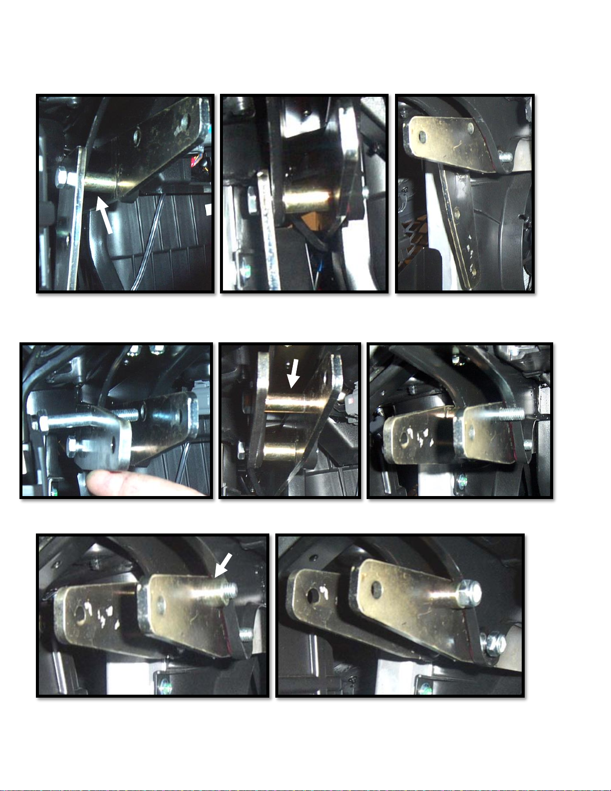
4
5. If you have an X4 model, insert the spacer (O)between the shock mount tabs. If you have an X2 model,
insert and use spacer (81i) instead. Push the bolt through the spacer then slide the bolt through the
lowest hole on the long lift bracket and out through the inner shock mount tab. Loosely fasten it with a
(10mm lock nut).
6. Next, insert a bolt (10mm x 85mm bolt) through the next hole of the lift bracket. Place a spacer (9Y)
between the lift brackets. Slide the bolt through the spacer and out through the other lift bracket.
7. Now slide spacer (73P)over the threaded end of the bolt. Loosely fasten it with a (10mm lock nut).
5
8. Next you will reconnect the top of the shock to the lift brackets. Slide a (10mm x 70mm bolt) through
the third outer hole of the bracket and then place a small spacer (AA)over the threaded end of the bolt.
9. Slide the bolt through the shock eye and out through the other lift bracket. Loosely fasten it with a
(10mm lock nut).
10. Repeat steps for the opposite side.
11. Once all the brackets and bolts are in place, double check everything and fasten all the nuts tight.
12. Place wheels back on the UTV, torque all lugs to factory specifications.

6
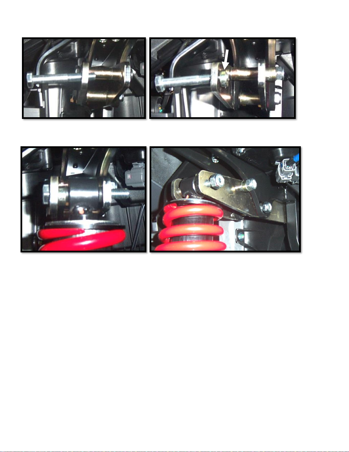
REAR LIFT INSTALLATION
1. Place jack under the center of the UTV, just forward of where the rear drive shaft connects to the engine,
and lift until the weight is off the suspension. Be careful to secure the UTV properly so it is stable on the
jack.
2. Remove the rear wheels.
3. Starting on the right side, disconnect the top of the shock from the UTV.
4. Place the rear lift bracket (81J-L) to the outside of the outer shock tab. The lower portion of the bracket
will come to rest to the inside of the lower portion of the frame.
5. Slide a (12mm x 80mm bolt) through the top hole of the lift bracket and through the outer shock mount
tab.

7
6. Next you will need to insert a spacer (4X)between the shock mount tabs. Slide the bolt through the
spacer and through the inner shock mount tab.
7. Place the other rear lift bracket (73O-L) to the outside of the inner shock mount tab and slide the bolt
through. Loosely fasten it with a (12 mm lock nut).
8. The lower portion of the lift bracket needs to be connected to the frame. Insert a (10mm x 75mm bolt)
through the hole of the frame that lines up with the lower hole of the lift bracket.

8
9. Insert a spacer (73Q)in between the frame brackets and slide the bolt all the way through the other lift
bracket. Loosely fasten it with a (10 mm lock nut).
10. Next you are going to connect the top end of the shock to the lift brackets. You will first slide a (12mm x
80mm bolt) through the lift bracket.
11. Insert spacer (AA)between the outer lift bracket and shock eye. Then insert another spacer (AA)
between the shock eye and inner lift bracket. Slide the bolt all the way through and loosely fasten with a
(12 mm lock nut).

9
12. Fasten all the nuts tight and repeat steps for the opposite side.
Note: The shock eye and spring may to appear to have tighter clearances now, but they do clear
from contacting any other parts.
13. Place wheels back on UTV and torque lugs to factory specifications.
LOGO PLATE INSTALLATION
1. Center the logo plate (10Y)on the tail gate.
2. Once you find the center, attach the plate to the tail gate using the self tapping screws (T141).

10

11
Read before Installation
This product is designed for use on ATVs and/or RUVs to increase ground clearance and fender clearance.
Purchasers should be aware that use of this product may increase the frequency of required maintenance, part
wear, and will raise the center of gravity on your ATV and/or RUV, increasing risk of roll-over, injury and
death on all types of terrain. It is your responsibility to always inform other operators and passengers of this
vehicle about the added risks.
High Lifter Products, products are designed to best fit users ATV/RUV under stock conditions. Adding,
modifying, or fabricating any OEM or aftermarket parts will void warranty. High Lifter Products, products
could interfere with other aftermarket accessories. If the user has aftermarket products on machine, contact
High Lifter Products to verify that they will work together. Adding aftermarket suspension components
and/or more aggressive tires can cause breakage of other OEM driveline components such as differentials,
axles or drive shafts.
We recommend that wider tires and/or wheel spacers be used to achieve a wider stance and to improve
stability of the ATV and/or RUV. Riders should be advised that the handling characteristics of a taller ATV
and/or RUV are different and require extra care when riding, particularly on side hills or off-camber situations.
If you further raise the center of gravity by adding taller tires, heavy loads to racks or seats, or by any other
means, the ATV and/or RUV must be operated with even more care, at slower speeds and on relatively flat
ground. All turns should be done at a slow speed, even on level ground.
Operation of an ATV and/or RUV with or without modified suspension components, while or shortly after
consuming alcohol or drugs, subjects the rider to the risk of serious bodily harm or possible death. This risk is
compounded if the rider does not wear an approved helmet and other safety gear. High Lifter urges that all
approved safety gear be worn when riding an ATV and/or RUV as a driver or passenger.
By purchasing and installing High Lifter Products, products, user agrees that should damages occur, High
Lifter Products will not be held responsible for loss of time, use, labor fees, replacement parts, or freight
charges. High Lifter Products will not be held responsible for any direct, indirect, incidental, special, or
consequential damages that result from any product purchased from High Lifter Products. The total liability of
seller to user for all damages, losses, and causes of action, shall not exceed the total purchase price paid for the
product that gives rise to the claim.
Dealers and other Installers
You are responsible for informing your customer and end user of the information contained above and the
increased potential hazards of operating an ATV and/or RUV equipped with modified suspension
components. If you install any suspension modifying components, it is your responsibility to also install the
warning label prominently in view of the driver and in prominent view of the driver and passenger on RUVs
and multi-passenger ATVs. They should also be instructed to notify anyone operating the vehicle, as well as
any passengers, that said vehicle is modified.
As discussed above, it is critically important that they be instructed in the need for slower speed operation,
regardless of terrain, after this lift kit is installed.

12
High Lifter Lifetime Warranty
From the beginning, High Lifter has engineered and manufactured some of the toughest, most durable products
on the market. That’s why this product comes with a Lifetime Warranty. It’s our promise that High Lifter will
never let you down.
•The Lifetime Warranty covers products sold to the original purchaser only and is not transferable. The term of
the warranty is for the lifetime of the vehicle in question.
•Normal wear and tear items and finishes, such as, but not limited to: Heim joints, tie rod ends,
ball joints, bearings, seals, bushings, bushing sleeves, zinc plating , powder coating, or chipping and
discoloration of any finish is not covered.
•High Lifter will ship the replacement product after the returned product has been inspected by High Lifter
staff.
•The warranty shall not include claims for damages, installation time or labor charges, economic losses,
inconvenience, transportation, towing, down time, direct or indirect or consequential damages or delay
resulting from any defect.
•The warranty does not apply to products that have been improperly applied or improperly installed.
Making a warranty claim
1. All claims must be accompanied by the part and the original sales receipt or other acceptable proof of
purchase from the original owner.
2. All warranties must be accompanied with a Return Merchandise Authorization (RMA) number. (Contact High
Lifter at 318-524-2270 or 800-699-0947 for an RMA number)
3. When shipping the damaged product:
a. Write the RMA number on the outside of the box.
b. Also include the RMA number, proof of purchase and any notes inside the box.
c. Please keep your tracking number and shipment information.
4. The customer is responsible for shipping the product to High Lifter--return shipping within the lower 48 states
will be paid by High Lifter products. With all warranty claims, only standard shipping services apply.
5. High Lifter will process your order within 24 business hours of receiving the returned item.
6. Ship to: High Lifter Products, 780 Professional Drive North, Shreveport, Louisiana 71105
This manual suits for next models
1
Other High Lifter Automobile Accessories manuals


