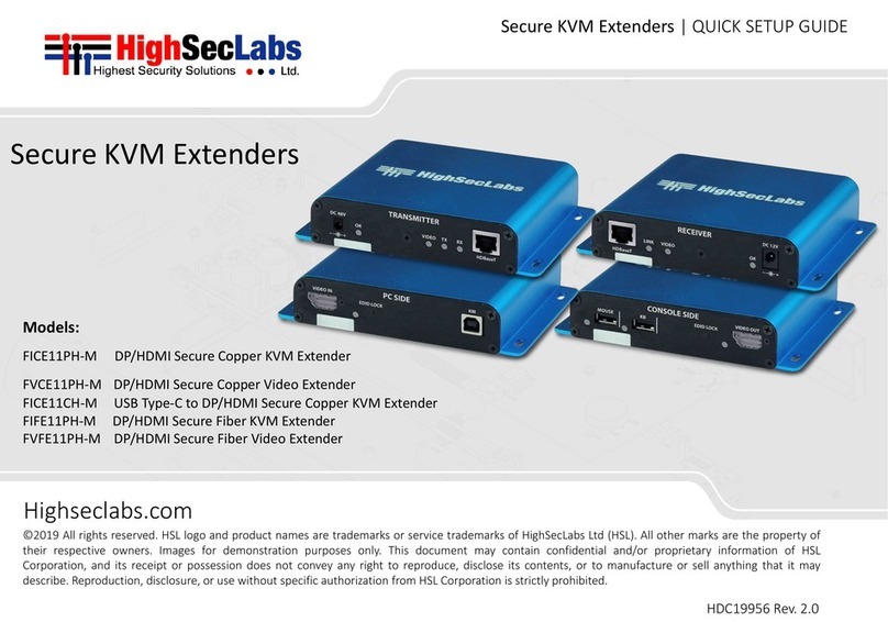
High Sec Labs FICE11PH-M User manual

Models:
FICE11PH-M - DP/HDMI Secure Copper KVM Extender
FVCE11PH-M - DP/HDMI Secure Copper Video Extender
FIFE11PH-M - DP/HDMI Secure Fiber KVM Extender
FVFE11PH-M - DP/HDMI Secure Fiber Video Extender HDC19956 Rev. 3.4
SECURE KVM EXTENDERS | QUICK SETUP GUIDE

1
HSL Secure Extended Isolators Quick Setup Guide
TABLE OF CONTENTS
SECTIONS
Table of Contents 123
Introduction .......................................................... 2
HSL Secure KVM Extenders Family ............................................2
Installation............................................................ 3
Operation............................................................. 7
Running an EDID Capture .....................................................7
Safety and Regulatory Statements..................................... 8

2
HSL Secure Extended Isolators Quick Setup Guide
INTRODUCTION
SECTIONS
Table of Contents 2 3
1
HSL Secure KVM Extenders Family
The Secure KVM Extender extends video, audio and Keyboard/Mouse
signals up to hundreds of meters while it prevents vulnerable peripherals
from mediating between compromised and secure computers by
ensuring that video, audio and KM flow are in a single direction.
Up to 100 m
(COPPER)
Up to 10 km
(FIBER)
Display or Projector
Transmitter
Video
USB KB
& Mouse
IR
Reciever Audio
RS232
Controller
Computer
or Matrix
Video
Audio
USB KB
& Mouse
IR

3
HSL Secure Extended Isolators Quick Setup Guide
INSTALLATION
SECTIONS
Table of Contents 1 3
2
Step 1 – Connect the Secure KVM Extender’s Receiver and the
Transmitter parts
The device’s Receiver and Transmitter may be located in different
rooms or even different buildings.
Connect the two parts with a suitable cable through the connection
port:
•Models FICE11PH-M, FVCE11PH-M and FICE11CH-M - with a
Copper Cable
•Models FIFE11PH-M and FVFE11PH-M - with Optical Fiber Cable
Note: If either LED remains OFF, the Isolator does not recognize the
device. Use an alternative device! Transmitter
EDID LEDs
Receiver
KB/Mouse
LEDs
EDID LEDs

4
HSL Secure Extended Isolators Quick Setup Guide
INSTALLATION
SECTIONS
Table of Contents 1 3
2
Step 2 – Connecting the Transmitter (PC side) to the PC
1. Video connection: For all models, connect the PC to the Isolator
Extender’s VIDEO IN port, using the HDMI or DP video cable
2. PC Keyboard and Mouse connection: For FICE11PH-M, FIFE11PH-M
models, connect the PC to the Isolator using a USB A to USB B cable.
Connect the USB A end to the PC and the USB B end to the Isolator
Extender’s COMP/MOUSE port.
EDID LEDs
Video in Port
Host KB/Mouse
Power LED
Video Transfer
LED Rx to Tx
Connection LED

5
HSL Secure Extended Isolators Quick Setup Guide
INSTALLATION
SECTIONS
Table of Contents 1 3
2
Step 3 – Connecting the peripherals to the
Secure KVM Extender Receiver (CONSOLE SIDE)
1. Video connection: For all models, connect the monitor/projector
cable to the Isolator’s VIDEO OUT port.
2. PC keyboard and mouse connection: For FICE11PH-M, FIFE11PH-M
models, connect a USB mouse and keyboard, to the Isolator Extender
Receiver’s corresponding MOUSE and KB ports.
Both mouse and keyboard LEDs should light continuously green when
KB and Mouse are connected and device is turned on.
Note: If either LED remains OFF, the Extended Isolator does not
recognize the device.
Use an alternative device!
Rx to Tx
Connection LED
Video Transfer
LED
Power LED
EDID LED
EDID Lock
KB/Mouse LED

6
HSL Secure Extended Isolators Quick Setup Guide
INSTALLATION
SECTIONS
Table of Contents 1 3
2
Step 4 – Power ON
1. For all models, connect the power adapters on both the Secure
KVM Extender’s Transmitter and Receiver at the PC SIDE, DC IN port.
Power ON the unit by plugging it into an AC wall outlet.
2. The PC SIDE Power LED should light green continuously. If not, check
the connections.
Step 5 – Make sure the connected PC on the Transmitter side and
Display or Projector on the Receiver side are powered ON.
Power LED
Power LED

7
HSL Secure Extended Isolators Quick Setup Guide
OPERATION
SECTIONS
Table of Contents 123
Running an EDID Capture
Before using the Extender, run a one-time EDID capture on both sides
– Transmitter and Receiver. This prevents the continuous transfer of
potentially malicious data - from the display to the PC – that could
infect the PC, cause data leakage, and so on.
Preparation:
•Connect the PC and all peripherals to both the units, according to
the Installation Instructions.
•Make sure the PC, display, and the units are ON.
To run an EDID capture:
1. On the Receiver, short-click the EDID Lock button. Wait 5 seconds
and then restart the unit, by unplugging the network cable and
power supply. At first, the EDID LED flickers for a few seconds and
then, once captured lights green continuously.
2. Make same on the Transmitter, short-click the EDID Lock button,
wait 5 seconds and then restart the unit. The EDID LED will now light
green continuously.
Note: If the EDID LED is OFF, check the connections and that the PC
or the Display are powered ON. Then, repeat the procedure.
3. Restart both units.
Note: An EDID capture needs to be performed for new installations
and when changing a display.
Transmitter
EDID LED
EDID Lock Button
Receiver
EDID LED
EDID Lock Button

8
HSL Secure Extended Isolators Quick Setup Guide
SAFETY AND REGULATORY STATEMENTS
SECTIONS
Table of Contents 123
Supported Hardware
This one or more of the following symbols may be included in your product
documentation and/or on the product.
Instructions: This symbol is intended to alert the user to the presence of
important operating and maintenance (servicing) instructions in the product
user manual.
Dangerous Voltage: This symbol is intended to alert the user to the presence
of uninsulated dangerous voltage within the product’s enclosure that may be
of sufficient magnitude to constitute a risk of electric shock to persons.
Power On: This symbol indicates the principal on/off switch is in the ON
position.
Power Off: This symbol indicates the principal on/off switch is in the OFF
position.
Protective Grounding Terminal: This symbol indicates a terminal which must
be connected to earth ground prior to making any other connections to the
equipment.
Safety Precautions
WARNING: To avoid a potentially fatal shock hazard and possible damage to equipment,
please observe the following precautions.
•Instructions: Do not disable the power grounding plug. The grounding plug is an
important safety feature.
•Plug the power cord into a grounded (earthed) outlet that is easily accessible at
all times.
•Disconnect the power from the product by unplugging the power cord from
either the electrical outlet or the product. The AC inlet is the main disconnect for
removing power to this product. For products that have more than one AC inlet, to
remove power completely, all AC line cords must be disconnected.
•This product has no serviceable parts inside the product enclosure. Do not open
or remove product cover.
This product is for use with other products that are Listed or Certified by a Nationally
Recognized Testing Laboratory (NRTL).
NIAP Protection Profile
This product is compliant with the NIAP Protection Profile PSD version 4.0 certification
for peripheral sharing switch devices.
Installation Precautions
Note: HSL Secure Extended Isolators are protected with Holographic Tamper-Evident Labels
on the product’s enclosure to provide a visual indication in case the enclosure has been
opened or compromised.
Do not connect this product to computing devices that:
•are TEMPEST computers
•include telecommunication equipment
•include frame grabber video cards
•include special audio processing cards
WARNING: Peripherals’ Warning - For security reasons, this product does not support wireless
keyboards. It is recommended not to connect a microphone or headset to the audio output port.
Security Vulnerability
If you are aware of a potential security vulnerability while installing this product,
contact Technical Support immediately by:
•Web form: www.highseclabs.com/support/case/
•Email: security@highseclabs.com
•Tel: +972-4-9591191/2
WARNING: Unit Enclosure Warning - If the unit’s enclosure appears disrupted or if all LEDs flash
continuously, remove the product from service immediately and contact Technical Support.

©2023 All rights reserved. HSL logo and product names are trademarks or service trademarks of HighSecLabs Ltd (HSL). All other marks are the property of their respective owners.
Images for demonstration purposes only. This document may contain confidential and/or proprietary information of HSL Corporation, and its receipt or possession does not convey any
right to reproduce, disclose its contents, or to manufacture or sell anything that it may describe. Reproduction, disclosure, or use without specific authorization from HSL Corporation
is strictly prohibited.
Highseclabs.com
Other manuals for FICE11PH-M
1
This manual suits for next models
3
Table of contents
Other High Sec Labs Extender manuals
Popular Extender manuals by other brands
hyfire
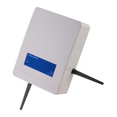
hyfire HFW-CEM-02 quick start guide
opticis
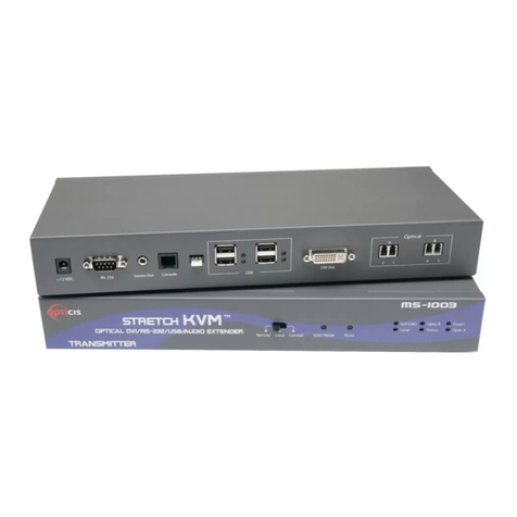
opticis DVI/USB/RS-232 and Audio Optical Extender user manual

Microsoft
Microsoft Windows Media Center Extender user guide
Speaka Professional
Speaka Professional RF-HDFS-02 operating instructions

Marmitek
Marmitek MegaView 121 user manual
Intelix
Intelix VGA-HR installation guide
