High Voltage DTS-60A User manual

DTS-60A
Dielectric Oil Test Set
Operator’s Manual
Version 1.20
HighVoltage
INC
.

DTS-60A OPERATORS MANUAL
All rights reserved. Total or partial reproduction of this manual, whether by printed or
electronic means, is forbidden. Information regarding any errors found in it or suggestions
concerning improvement are appreciated. Since products are subject to continuous check
and improvement, High Voltage inc. reserves the right to make changes in information
contained in this manual without prior notification.
Manual Revision 07/03/2008 Version 1.20
Copyright 2005 High Voltage inc. – USA
HIGH VOLTAGE, INC.
31 County Route 7A
Copake, N.Y. 12516
Phone : 518/329-3275
Fax : 518/329-3271
Web :
http://www.hvinc.com
e-mail: [email protected]

DTS-60A OPERATORS MANUAL
DTS-60A OPERATORS MANUAL
Icons & Notation
This icon indicates danger conditions!
Danger!
This icon indicates warnings!
Warning!
This icon indicates a hint or a tip!
Note!

DTS-60A OPERATORS MANUAL
DTS-60A OPERATORS MANUAL
This Operator manual contains instructions
for the operation of a High Voltage power
source. The operator of this equipment must
use good judgement and follow all safety
precautions noted in this guide to ensure the
protection of himself and others in close
proximity to the test area. Failure to follow
the instruction could result in injury or
death.
Proper grounding of the test set must be
done prior to connecting this unit to a power
source.

DTS-60A OPERATORS MANUAL

DTS-60A OPERATORS MANUAL
Table of Contents
1. Specifications and Controls
1. Features and Specifications
2. ControlPanel
3. User Interface
1. MenuOverview
2. KeyboardOperations
3. Warning Messages
4. QuestionMessages
5. ErrorMessages
6. Indicators
4. Setup the Equipment
5. Using the Shielded Output Cables
6. Startup the Equipment
2. Menu/ Submenus and Settings
1.
Main Menu Overview
2. MainMenu
3. ProgramsSubmenu
4. SettingsSubmenu
1. Time/DateSetup
2. OperatorSetup
3. LCDContrastSetup
4. LanguageSetup
5. RegionSetup
3. SimpleTest
1. SimpleTestOperations
2. Simple Test Initialization
3. Simple Test Execution
4. SimpleTestTermination
5. SimpleTestExample
4. StandardTests
1. StandardTestDescription
2. SelectaStandardTest
3. StandardTestExecution
4. StandardTestExample

DTS-60A OPERATORS MANUAL
5. UserDefinedTests
1. TestDescription
1. TestStructure
2. TestOperations
2. TestMenu
1. SelectTest
2. CreateTest
3. EditTest
4. DeleteTest
3. Script Files for Tests
1. Script File Commands and Arguments
2. ScriptFileTestExample
6. History and Results
1. +++
2. +++
7. PrinterandPrintouts
1. PrinterDescription
2. ChangingthePaperRoll
3. PrintoutDescription
8. RemoteOperation
1. Enable the Remote Operation
2. VerCommand
3. clsCommand
4. timeCommand
5. dateCommand
6. operatorCommand
7. contrastCommand
8. program Command
1. program list Command
2. program read Command
3. program delete Command
4. program download Command
9. historyCommand
CareandMaintenance
Appendix I Standard Test Script Files
Appendix II Firmware Upgrade Procedure
Acronyms&Abbreviations
Index


DTS-60A OPERATORS MANUAL
1
1
Specifications and Controls
This section familiarizes the operator with the features and the
specifications of the DTS-60A AC Dielectric Oil Test Set manufactured
by High Voltage, inc. Moreover, a brief introduction about the
equipment’s set-up and start-up is presented.
1. Features and Specifications 1-2
2. Control Panel
1-4
3. User Interface
1-5
1. Menu Overview 1-5
2. Keyboard Operations 1-6
3. Warning Messages 1-8
4. Question Messages 1-10
5. Error Messages 1-12
6. Indicators 1-13
4. Setup the Equipment
1-14
5. Using the Shielded Output Cables 1-15
6. Startup the Equipment
1-16

DTS-60A OPERATORS MANUAL
2
1.1 Features and Specifications
The DTS-60A AC Dielectric Oil Test Set provides automatic,
programmable and accurate measurement of breakdown voltage for
insulating oils used in high-voltage electrical equipment.
Main features of the DTS-60A Series of AC Dielectric Oil Test Set
User Interface
Dot Matrix Liquid Crystal Display (128x64)
Compact 5-key keyboard for operation
User friendly, menu driven functionalities
Large Output Voltage Digits (3.1 digits)
Functionalities
Test-Result report
Real-Time clock
Ambient Temperature measurement
International Standard Tests
User defined Tests
Test-Results storage
Language selection
Measurements and Control
High accuracy of High Voltage measurement (0.5%)
Digitally selected Voltage rate of rise (0.1kV/s step)
Arc detection with less than 5 milliseconds shutdown
Digital Closed-Loop for voltage control
Equipment Case
Rugged aluminum case
Window for observation of oil test

DTS-60A OPERATORS MANUAL
3
Table 1.1 - Specifications
DTS – 60A
Input 120V, 50/60 Hz, 5 amps, single phase
230V, 50/60 Hz, 3 amps, single phase
Output 0 – 60kVac, 800VA resistive load, between bushings
Output Termination Dual Capacitively Graded Bushings
Display Dot-Matrix 128x64
Keyboard 5 keys for equipment’s functionalities
Printer Optional 40 columns dot-matrix
Remote Management RS-232 Serial Interface
Breakdown Shutdown Less than 5 ms
Accuracy 0.5%
Operating
Temperature -14 F to 104 F (-10 C to 40 C)
Case Size 14.75w x 14d x 11.5h in (36.88w x 35d x 28.75h mm)
H.V. Tank High Voltage Tank Included
Weight 60 lbs.

DTS-60A OPERATORS MANUAL
4
1.2 Control Panel
The equipment’s Control Panel is depicted in Figure 1.1. It
consists of the following:
Input Power
The Input Power connector accepts most standard
electrical equipment type cords. The power supplied to
the input connector must be from a grounded source
rated to match the input power specifications noted in
Table 1.1.
Main Power
The Main Power switch provides the power to the
control and power circuits. The neon lamp will light
when the power is on and the voltage is available
through the input line cord. The Input Power Fuse
located electrically before the Main Power switch
provides line fault protection for the unit.
Fuse Socket
LCD display
The Liquid Crystal Display guides the user to the
system’s functionalities.
Keyboard
Compact 5-key keyboard for equipment operation.
Figure 1.1 – DTS-60A Control Panel

DTS-60A OPERATORS MANUAL
5
1.3 User Interface
The equipment User Interface is based on a dot-matrix Liquid
Crystal display (LCD) and a compact 5-key keyboard, Figure 1.2. The
user-friendly graphical interface makes the equipment's operation
simple and attractive.
Figure 1.2 – Equipments User Interface
1.3.1 Menu Overview
The equipment operation is based on a user friendly structure of
menu/ submenu driven functions. An overview of the menu/
submenu selections is summarized in Figure 1.3.
Figure 1.3 – Equipment's User Interface
MENU
TESTS
SETTINGS
TEST HISTORY
REMOTE OPERATION
TESTS
SELECT
CREATE
EDIT
DELETE
SETTINGS
TIME/DATE
OPERATOR
LCD CONTRAST
LANGUAGE
TEST HISTORY APP
REMOTE OPERATION APP
SELECT TEST APP
CREATE TEST APP
EDIT TEST APP
DELETE TEST APP
SETUP TIME/DATE APP
SETUP OPERATOR APP
SETUP LCD CONT. APP
SETUP LANGUAGE APP
REGION SETUP REGION APP

DTS-60A OPERATORS MANUAL
6
1.3.2 Keyboard Operations
Although most of the keyboard operations are based on similar
methods, there are some cases where an optional key functionality is
enabled. These exceptions are described analytically in the
respective manual paragraphs.
The most common keyboard operations are the following:
Menu and Submenu Operations
MENU Enter to the Menu or Selected Submenu
BACK Exit from Menu or Current Submenu
UP Go to the previous selection
DOWN Go to the next selection
ENTER Enter to the selection
Simple Test Operations
MENU Enter to the Menu or Selected Submenu
BACK Enable/ Disable Stirrer
UP Increase Voltage Rate of Rise
DOWN Decrease Voltage Rate of Rise
ENTER Execute Test
ANY After Starting the Test ANY key interrupts the
process
Number Edit Operations
MENU -
BACK Discard changes and return
UP Increase the current value
DOWN Decrease the current value
ENTER Enter the value
String Edit Operations
MENU Select Capitals, Smalls, Numbers, Symbols
BACK Delete Character
UP Select previous character
DOWN Select next character
ENTER Enter the string
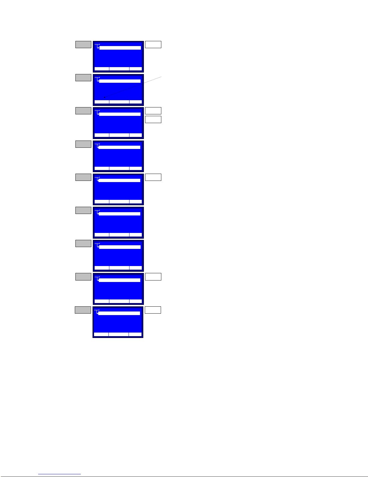
A detailed example follows, Figure 1.4, in order to clarify the
String Edit keyboard operation. The example refers to a string entry
for the Name of the Operator Setup menu (see paragraph 2.3.2).
DTS-60A OPERATORS MANUAL
7
Figure 1.4 – String Entry Keyboard Operation
OPERATOR
12:10 01/08/04 25 C
NAME
COMPANY
CONTACT INFO
OTHER INFO
Press the ENTER key in order to enable the String
Entry keyboard operation for the Name
OPERATOR
CONTACT INFO
OTHER INFO
_
STEP 1
The String Entry Cursor is displayed. This
indicates the current possition of the editable
character.
OPERATOR
CONTACT INFO
OTHER INFO
O
Use the UP and DOWN keys to select the desired
character. Dont leave more than 2 seconds
between key pressings. After every UP key
pressing the next character of the alphabet will be
displayed. In contrast, after every DOWN key
pressing the previous character of the alphabet will
be displayed. The character sequency is circular.
OPERATOR
CONTACT INFO
OTHER INFO
O_
Stop pressing the UP and DOWN keys for more
than 2 seconds. The character will be entered and
the cursor will be displayed in the next possition.
STEP 2
STEP 3
STEP 4
ENTER
UP
DOWN
OPERATOR
CONTACT INFO
OTHER INFO
_
A mistake occured! Press the BACK Key in order
to delete the last entried character.
OPERATOR
CONTACT INFO
OTHER INFO
P_
Select the correct character according STEP 3
instructions. Then wait 2 seconds, until the cursor
is displayed at the next possition.
OPERATOR
CONTACT INFO
OTHER INFO
PETER_
Repeat the character entry operation for the whole
string.
OPERATOR
CONTACT INFO
OTHER INFO
PETER_0
Press the MENU key twice, in order to enter
numbers in the string.
STEP 5
STEP 6
STEP 7
STEP 8
BACK
MENU
COMPANY
COMPANY
COMPANY
COMPANY
COMPANY
COMPANY
COMPANY
NAME
NAME
NAME
NAME
NAME
NAME
NAME
12:10 01/08/04 25 C
12:10 01/08/04 25 C
12:10 01/08/04 25 C
12:10 01/08/04 25 C
12:10 01/08/04 25 C
12:10 01/08/04 25 C
12:10 01/08/04 25 C
OPERATOR
CONTACT INFO
OTHER INFO
PETER_007
Press the ENTER key in order to enter the edited
sting and return.
STEP 9 ENTER
COMPANY
NAME
12:10 01/08/04 25 C
DTS-60A OPERATORS MANUAL
8
1.3.3 Warning Messages
Display shows Warning Messages in the following cases.
1. Lid is Open, Figure 1.5.
This warning message is displayed when the Lid of the
equipment is open and a test procedure is enabled. The
current operation (i.e. test execution) will be restarted when
the lid will close.
Warning Message
PROGRAM : ASTM-D1816
12:10 01/08/05 65 °F
Lid is Open
DURATION: 00:00:00
SYSTEM HALTED...
Figure 1.5 – ‘Lid is open' Warning Message
If the Warning Message “Lid is Open” is
depicted when the Lid is closed, contact
the distributor or the manufacturer.

DTS-60A OPERATORS MANUAL
9
2. Verify Electrode/Gap Spacing, Figure 1.6a/b.
This warning message is displayed at the startup of every
test procedure, in order to remind the user to check the
electrodes type and spacing, according to the selected test.
If the selected test is a standard one (where the spacing
and the type of the electrodes is specific) the message will
inform the user for the appropriate settings (type, spacing),
Figure 1.6a. The user may release the system by pressing
the ‘ENTER’ key.
Warning Message
PROGRAM : ASTM-D1816
12:10 01/08/05 65 °F
Electrodes:
Space: 0.04±0.0010in
DURATION: 00:00:00
SYSTEM HALTED...
Figure 1.6a – ’Electrodes/ Space’ Warning Message
If the selected test is the Simple Test (where the
spacing and the type of the electrodes is not specific) the
message will prompt the user for verification of the desired
electrode type and spacing, Figure 1.6b. The user may
proceed by pressing the ‘ENTER’ key.
Warning Message
PROGRAM: SIMPLE TEST
12:10 01/08/05 65 °F
Verify Electrodes &
Gap Spacing
VOLTAGE: 0.5 kV/s
DURATION: 00:00:00
Figure 1.6b – Verify Electrode/Gap Spacing’ Warning Message
DTS-60A OPERATORS MANUAL
10
1.3.4 Question Messages
The unit may display the following Question Messages.
1. Continue Test?, Figure 1.7.
This question message is displayed after a breakdown
detection in the Simple Test procedure. The system
prompts the user for continuing the current test with a new
stage, or terminating the test. User may press the ‘ENTER’
key for continuing the test, or the ‘BACK’ key for
terminating the test. All other keys are disabled.
Question Message
PROGRAM: SIMPLE TEST
12:10 01/08/05 65 °F
Continue Test?
Yes:
No:
VOLTAGE: 0.5 kV/s
DURATION: 00:00:30
?
ENTER
BACK
Figure 1.7 – ‘Continue Test?’ Question Message
2. Print Results?, Figure 1.8.
This question message is displayed only if the equipment
has a printer. The message prompts the user for printing
the test report after a test is finished. User may press the
‘ENTER’ key for printing the test report, or the ‘BACK’ key
for discarding the printing. All other keys are disabled.
Question Message
PROGRAM: SIMPLE TEST
12:10 01/08/05 65 °F
Print Results?
Yes:
No:
VOLTAGE: 0.5 kV/s
DURATION: 00:00:30
?
ENTER
BACK
Figure 1.8 – ‘Print Results?’ Question Message
Other manuals for DTS-60A
1
Table of contents
Other High Voltage Test Equipment manuals


Popular Test Equipment manuals by other brands


Bosch
Bosch MTS 6513 user manual

Fluke
Fluke 5522A Operators Operator's manual

IDEAL
IDEAL LinkMaster PRO XL instructions

Static Solutions
Static Solutions OHM-STAT CT-8900 Owners manual and operation guide

Leslie's
Leslie's AccuBlue Home quick start

Sartorius Stedim Biotech
Sartorius Stedim Biotech 16756 operating instructions


