MSG MS900 User manual

2023.05.25
MS900
STAND FOR WASHING
OF PARTICULATE FILTERS (DPF, FAP)
UNIQUENESS
TRAINING
SERVICE
INNOVATIO
N
WARRANTY
QUALITY
EU
USER MANUAL
UA
ІНСТРУКЦІЯ З ЕКСПЛУАТАЦІЇ
PL
INSTRUKCJA OBSŁUGI
ES
MANUAL DE USUARIO
RU
РУКОВОДСТВО ПО ЭКСПЛУАТАЦИИ

ENGLISH
USER MANUAL
MS900 – STAND FOR WASHING OF PARTICULATE
FILTERS (DPF, FAP)
3-28
УКРАЇНСЬКА
ІНСТРУКЦІЯ З ЕКСПЛУАТАЦІЇ
MS900– СТЕНД ДЛЯ ПРОМИВАННЯ САЖОВИХ
ФІЛЬТРІВ (DPF, FAP)
29-54
POLSKI
INSTRUKCJA OBSŁUGI
MS900– STANOWISKO DO PŁUKANIA FILTRÓW
CZĄSTEK STAŁYCH (DPF, FAP)
55-80
ESPAÑOL
MANUAL DE USUARIO
MS900– MÁQUINA DE LIMPIEZA DE FILTROS DE
PARTÍCULAS (DPF, FAP)
81-106
РУССКИЙ
РУКОВОДСТВО ПО ЭКСПЛУАТАЦИИ
MS900– СТЕНД ДЛЯ ПРОМЫВКИ САЖЕВЫЖ
ФИЛЬТРОВ (DPF, FAP)
107-132

English
User manual
3
CONTENT
INTRODUCTION....................................................................................................................................................4
1. APPLICATION....................................................................................................................................................4
2. SPECIFICATIONS..............................................................................................................................................4
3. EQUIPMENT SET ..............................................................................................................................................5
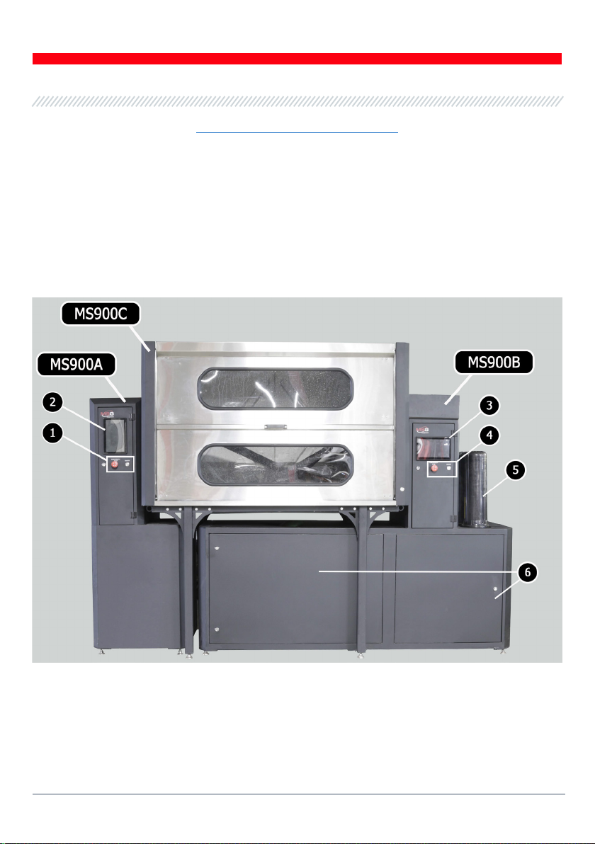
4. STAND DESCRIPTION ....................................................................................................................................6
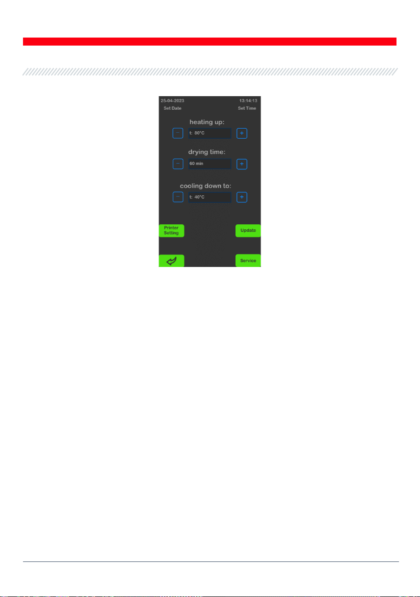
4.1. MS900A module control menu ............................................................................................................7
4.2. MS900B module control menu ......................................................................................................... 11
5. INTENDED USE ..............................................................................................................................................13
5.1. Safety Guidelines...................................................................................................................................14
5.2. Stand installation and preparation for operation .......................................................................14
6. FILTER CLEANING .........................................................................................................................................15
7. STAND MAINTENANCE..................................................................................................................................18
7.1. Replacement of the three polypropylene filters ..........................................................................18
7.2. Cleaning the hydrocyclone..................................................................................................................18
7.3. Checking and cleaning the three-way valve ................................................................................. 20
7.4. Replacement of the blower air filter................................................................................................22
7.5. Water tank replacement......................................................................................................................23
7.5.1. Draining water from the tank without activating the pump ............................................23
7.6. Software update ................................................................................................................................... 24
8. TROUBLESHOOTING GUIDE ........................................................................................................................25
9. RECYCLING.....................................................................................................................................................27
CONTACTS.......................................................................................................................................................... 28

English
MS900 stand
4
INTRODUCTION
Thank you for choosing TM "MSG Equipment" products.
This User Manual contains information about the purpose, equipment, technical specifications,
and operating rules of the MS900 stand.
Before using the MS900 stand (hereinafter referred to as the "stand"), carefully study this User
Manual and, if necessary, undergo special training at the stand manufacturer's facility.
Due to continuous improvements in the stand's design, equipment, and software (hereinafter
referred to as "software"), changes may be made that are not reflected in this User Manual. The
pre-installed software on the stand is subject to updates, and its support may be discontinued
without prior notice.
1. APPLICATION
The stand is designed for cleaning particulate filters (hereinafter referred to as "filters") of
passenger cars, trucks, and buses. Cleaning the particulate filters is done by flushing them with a
stream of warm water. By periodically changing the direction of the flow and delivering
compressed air pulses, high-quality cleaning of the particulate filter is achieved without the use
of cleaning agents. For convenience in keeping track of serviced filters, the stand allows saving
the results of the cleanings and printing them on an external Bluetooth printer (not included in
the package).
The stand consists of three modules:
MS900A – diagnostic and drying module;
MS900B – flushing module;
MS900C – washing and drying chamber.
The MS900A and MS900B modules are self-sufficient and operate independently of each other. If
the stand is equipped with two MS900C modules, it is possible to simultaneously service two
filters.

English
User manual
5
2. SPECIFICATIONS
Supply voltage, V
400 and 230
Supply mains type
Three-phase and single-phase
Power consumption, kW
20.6
Dimensions (L×W×H), mm
2600×840×2050
Weight, kg
400
Control
Touchscreen
Type of filters to be flushed
DPF (DPF + SCR)
FAP (FAP + SCR)
GPF
Diagnostic and drying of the particulate filter
Diagnostic time, minutes
up to 1
Recommended drying time, minutes
10 – 20
Air temperature during drying, °C
up to 80
Dimensions of the washing chamber
(W×D×H), mm
1600×750×955
Opening system for the washing chamber
doors
Manual
Workspace lighting
Available
Need for an exhaust ventilation system
Yes (recommended), minimum 450 m
3
/h
Ventilation connection mounting diameter,
mm
125
Particulate filter flushing
Recommended washing time, minutes
20 – 30
Flushing liquid
Water
Water temperature during flushing, °C
up to 60
Water supply connection
G ½
Sewage connection
G 1 ½

English
MS900 stand
6
Filtering system for the flushing liquid
• hydrocyclone;
• 3 BB20 filters (5-20 microns).
Water storage tank capacity, liters
200
Requirement for compressed air supply
6-8 bar, 200 l/min
Additional features
Saving of washing results
Available
Printing of results
Available
Software update
Available

English
User manual
7
3. EQUIPMENT SET
The equipment complete set includes:
Description Quantity, pc.
MS900А module
1
MS900В module
1
MS900С module
1
Fitting for connecting the diesel particulate filter:
MS70001
MS70002
MS70003
MS70004
MS70006
Silicone adapter
90-degree angle camlock
2
2
2
2
2
2
2
Set of plugs
1
Hoses (2m, 1.8m, 1.3m)
3
Gasket for connecting blocks B and C
1
Metal clamp
2
BB20 filter (5-20 microns)
3
Filter replacement wrench
1
VMR 25 three-way valve wrench
1
Stand wrench
2
USB Type-C flash drive
1
User manual (card with QR code)
1

English
MS900 stand
8
4. STAND DESCRIPTION
The assembled stand looks as shown in Figure 1. The MS900A module is located on the left side
of the washing chamber (MS900C module) and has two buttons on the front panel: power on and
emergency stop button (see item 1). The MS900A module is controlled using a touch panel (see
item 2).
The MS900B module is located on the right side of the washing chamber and has two buttons on
the front panel: power on and emergency stop button (see item 4). The MS900B module is
controlled using a touchscreen (see item 3). The MS900B module has three containers with
replaceable filtering elements (see item 5). Removable panels are placed on the front and rear
sides of the stand to access the module's components for servicing purposes (see item 6).
Figure 1. External view of the stand
On the rear side of the MS900B module, there are connectors for compressed air, water supply,
and sewage.

English
User manual
9
4.1. MS900A module control menu
The MS900A module has two operating modes: diagnostics (see item 2 in Figure 2) and filter drying
(see item 1 in Figure 2). The module allows keeping a history of serviced filters (item 3). Module
settings can be accessed from the menu (see item 4).
Figure 2. Main control screen for the MS900A module
The "History of Serviced Filters" menu displays a calendar with the number of saved filter checks
(see Figure 3). Clicking on a date shows the filter check data for that day.
Figure 3. History of Serviced Filters menu

English
MS900 stand
10
The MS900A module's settings menu (Figure 4) includes:
Figure 4
"heating up" - air temperature during filter drying;
"drying time" - the duration of the filter drying process;
"cooling down to" - the temperature to which the filter will be cooled down after drying;
"Printer Setting" - menu for connecting the Bluetooth printer;
"Update" - software update for the module;
"Service" - service menu for the manufacturer's service department.
Clicking on a field with the date or time allows you to set them.

English
User manual
11
4.2. MS900B module control menu
Module MS900B is controlled through the menu shown in Figure 5.
Figure 5
1– Water temperature control in the tank. The water temperature can be adjusted during the
washing process. The "Filtration" button activates the preliminary water filtration process,
while the "Heating" button activates the preheating of the water.
2- Current status of the module.
3- Warning sign indicating a malfunction in the module's operation. Pressing the sign displays
the errors that caused the malfunction (see Figure 7).
4- Date and current time. Pressing this area opens the "Service" menu.
5- Saved washing parameters. Pressing and holding the button opens the settings menu (see
Figure 6).
6- Field displaying the selected washing parameters.
7- Pressure drop value across the module's filters. The higher the value, the more
contaminated the filter is. In case of critical contamination, the washing process stops or does
not start.
8- Button for additional air blowing of the filter to remove water from it. The air is supplied
while the button is held.
9- Remaining washing time (can be increased or decreased during the washing process).
10 - Button for draining water from the tank.

English
MS900 stand
12
11 - Button to activate the process of filling the tank with water. Pressing the button again
stops the process.
The washing process settings window allows you to set the following parameters:
Figure 6
"Time cycle" - total washing time.
"Impulse time" - duration of the compressed air pulse.
"Impulse pause" - time between compressed air pulses.
"Blow after wash" - time for air blowing of the filter after washing.
"Min tank level" - minimum water level in the tank at which the washing process stops. It is
recommended to maintain a level of 50% for washing passenger car filters and 90% for
commercial vehicles.
The information window (Figure 7) displays a list of detected errors. After resolving them, it is
necessary to clear the errors using the "Clear error" button, after which the module can continue
its operation. This window also allows access to the service menu.
Figure 7

English
User manual
13
The module's service menu (see Figure 8) contains:
Figure 8
1- Buttons for manual control of the module's components.
2- List of detected errors.
3- Information about the current version of the module's software.
"Clear error" - button to clear errors.
"Update" - button to update the module's software.
5. INTENDED USE
1. Use the stand only for its intended purpose (see section 1).
2. The stand is designed for indoor use at temperatures ranging from +10 to +40 °C and relative
air humidity of 10 to 75% without condensation.
3. Modifying the design and electrical circuit of the stand is not allowed.
4. Turn off the stand when it is not in use.
5. In case of failures in the operation of the tester, stop further operation and contact the
manufacturer or sales representative.
WARNING! The manufacturer is not responsible for any damage or injury to human health
resulting from non-compliance with the requirements of this user manual.

English
MS900 stand
14
5.1. Safety guidelines
1. Only specially trained personnel who have been authorized to work on specific types of stands
(instruments) and have undergone instruction on safe practices and methods may work with the
stand.
2. It is prohibited to open the door of the washing chamber during washing, drying, or
diagnosing the soot filter.
3. During operation, all removable panels must be properly installed.
4. The filter becomes highly heated during the drying process, so allow it to cool down to an
acceptable level before touching it.
5. Always open and close the door of the washing chamber (module MS900C) using the handle.
5.2. Stand installation and preparation for operation
The stand is delivered in packaging. After unpacking the product, it is necessary to ensure that
the stand is intact and free from any damage. The packaging materials should be properly
disposed of in designated areas for separate waste collection.
The stand is installed in a room on a level floor. The distance between the walls of the stand and
the walls of the room or other objects should be at least 1 meter to allow unobstructed servicing.
The first step is to install the MS900C module. On the left side of the MS900C module, install the
MS900A module. Adjusting the height of the module's legs, position them so that the hole in the
side wall of the MS900C module aligns with the CAMLOK connector on the MS900A module. Then,
move the MS900A module tightly against the MS900C module (see Figure 9). Similarly, install the
MS900B module on the right side of the MS900C module.
Follow the installation steps, which include connecting the neck of the MS900B module's tank to
the drain opening of the MS900B module using a clamp and securing it with clamps.
Next, you need to:
•Connect the ventilation system to the MS900C module.
•Connect the 400V power supply to the MS900A and MS900B modules, and the 230V power
supply to the MS900C module.
•Connect a compressed air source, water supply, and drainage system to the MS900B module.
•Fill the tank of the MS900B module with clean water to 60-70% of its capacity. The process
of water filling in the tank is controlled through the menu (see item 10 in Figure 5).

English
User manual
15
Figure 9. Position of CAMLOK connectors after installing the stand modules
6. FILTER CLEANING
The cleaning of the filter from soot is carried out through a 4-stage process:
1) Filter testing;
2) Washing;
3) Drying;
4) Re-testing the filter.
WARNING! When opening and closing the door of the washing chamber, always hold onto the
door handle to avoid injury.
Stage 1 - Filter Testing
•During the first stage, the filter's permeability is checked. To do this, attach a suitable fitting
to the filter and connect a hose from the MS900A module to the filter's inlet. On the main
screen of the MS900A module, start the diagnostic mode (see item 2 in Figure 2). In the opened
window, press the "Start" button (see Figure 10).

English
MS900 stand
16
Figure 10
•Upon completion of the diagnostic process, the measurement results will be displayed on the
screen. If the pressure value exceeds 100 mBar, the filter is considered dirty and requires
washing.
•After the diagnostic process is complete, the stand will stop operating. Next, disconnect the
hose from the filter.
The diagnostic results can be saved and printed using an external Bluetooth printer. To save the
diagnostic results, press the "Save" button, which will appear after the diagnostic process is
finished. You will be prompted to save it as a new result if it's the first filter diagnostic, or you can
save the data to a file for an already tested and washed filter (see Figure 11a). If saving as a new
result, provide the customer's name and order number, then press the "Save file" button (see
Figure 11b).
Stage 2 - Filter Washing
•Connect the filter to the hoses of the MS900B module; the connection side doesn't matter. In
the menu of the MS900B module, select the appropriate washing parameters for the filter (see
Figure 5, item 5), or set the desired parameters. Press the "Start" button to begin the washing
process. If necessary, the process can be interrupted or extended at any time.
•Upon completion of the washing, the stand will stop operating. Next, disconnect the hoses
from the filter.

English
User manual
17
а b
Figure 11
Stage 3 - Filter Drying
Connect a hose from the MS900A module to the filter's outlet. Activate the drying mode (see
item 1 in Figure 2) and start the process by pressing the "Start" button (see Figure 12). If necessary,
the process can be interrupted or extended at any time.
Stage 4 - Re-testing the Filter
After drying the filter, reconnect it from the outlet to the inlet. Then, start the diagnostic mode.
Upon completion, the results can be saved and printed.
Figure 12

English
MS900 stand
18
7. STAND MAINTENANCE
The stand is designed for long-term operation and requires regular maintenance for reliable
performance, including:
1) Replacement of three polypropylene filters BB20 (5-20 μm) (see item 5 in Figure 1), on average
after 3-4 washed soot filters. The degree of clogging is assessed based on the pressure drop
(see item 7 in Figure 5).
2) Cleaning the hydrocyclone MS900B module every 50 washed filters.
3) Checking the operation of the three-way valve VMR 25 every 50 washed filters. Clean if
clogged.
4) Replacement of the blower's air filter every 500 washed filters.
5) Replacement of the water in the tank once a month.
7.1. Replacement of the three polypropylene filters
Before replacing the filter, turn off the MS900B module. Use the filter replacement key to unscrew
the three filter canisters one by one.
Replace the filters with new ones and screw the canisters back on.
7.2. Cleaning the hydrocyclone
Before cleaning the hydrocyclone, turn off the MS900B module. Remove the front and back panels
of the housing (see Figure 13).

English
User manual
19
Figure 13
Connect a flexible 1/2" hose to the connector (item 2 in Figure 14). Connect the other end of the
hose to the sewage system. Open the valve (item 1 in Figure 14) and drain all the water from the
hydrocyclone.
Figure 14
Unscrew the two bolts on the hydrocyclone (item 1 in Figure 15) and remove the cover (item 2).
Figure 15

English
MS900 stand
20
Remove all the cleaning products from the hydrocyclone housing.
Then reassemble the hydrocyclone in the reverse order of disassembly, close the valve (item 1 in
Figure 14), and place the stand panels back in their position.
7.3. Checking and cleaning the three-way valve
To check the operation of the VMR 25 three-way valve (item 1 in Figure 16) of the MS900B module,
follow these steps:
Figure 16. Location of the VMR 25 three-way valve.
1. Go to the "Service" menu.
2. Open the door with the touch panel.
3. In the "Service" menu, press the "Valve direction water" button several times (refer to Figure 17)
and observe how the indicator moves on the VMR 25 valves (refer to Figure 18). In a properly
functioning valve, the indicator moves smoothly and always returns to its original position. If
there are deviations in the movement of the indicator (usually sticking in the middle position), it
requires cleaning.
This manual suits for next models
3
Table of contents
Languages:
Other MSG Test Equipment manuals
Popular Test Equipment manuals by other brands

Reed Instruments
Reed Instruments R5700 instruction manual

Softing IT Networks
Softing IT Networks LinkXpert manual

JDS Uniphase
JDS Uniphase T-BERD MTS 5800 Series Getting started manual

ring
ring RBA15 instructions

Agilent Technologies
Agilent Technologies 16048D Operation and service manual

RuiDeng
RuiDeng UM24 instructions

Digital Watchdog
Digital Watchdog SiteWatch DW-DTWT quick start guide

Sonotec
Sonotec Sonaphone Short instructions

Amphenol
Amphenol Temposonics M Series user manual

sauter
sauter TVP-L Series instruction manual

Viavi
Viavi NSC-200 user guide

Agilent Technologies
Agilent Technologies 4072A Advanced Pre-installation guide