High Voltage VLF-CM Series Guide
Safety,Operation,andProcedureInstructionsfortheVLFSeriesof
ACHipots
Danger- Lethal Voltages:
Equipment to be used by trained personnel only
This Operator Manual contains instructions for the operation of a High Voltage power source. The operator of this equipment
must use good judgement and follow all safety precautions noted in this guide to ensure the protection of himself and others in
closeproximitytothetest area. Failure to follow the instructions could result in injury
or death. Proper grounding of the test set must be done prior to
connecting this unit to a powersource.
Mine
VLF-CM
SERIES
Please Refer to
Documentation
Before Operation


Last saved 5/15/2018
T:\DOCUMENTS\Manuals\VLF\MANvlfCM_Rm_2k18.doc
VeryLowFrequency(VLF)ACHighVoltageTesting-OperatorsManualAddendum
Instrument Summary
This instrument is a Very Low Frequency AC high voltage test system – a VLF hipot. It is an AC hipot whose frequency
output is 0.1 Hz or lower, compared to the 50/60 Hz of a conventional AC hipot. The lower the frequency, the lower the
current and power it takes to test a capacitive load like a cable. At 0.1Hz, it takes 600 times less current and power,
compared to 60Hz, to apply an AC voltage to a cable or some other high capacitance load.
At 0.1Hz frequency output, one full cycle of the sine wave takes 10 seconds, 20 seconds at 0.05Hz, and 50 seconds at
0.02Hz. Even though each cycle of the waveform can take 10 seconds or longer, it is still alternating current – AC – and is
sinusoidal.
This is not a DC hipot and it does not operate in the same manner. When the voltage output is raised, the voltage will
climb to its peak and then descend back to zero. The output polarity of the set reverses (a solenoid switch can be heard)
and then climbs again in the opposite polarity. This rise and fall of the voltage is obvious on the voltmeter and is normal.
The current meter will also rise and fall as the cable charges and discharges every half cycle. Unlike DC, there are no
leakage currents to read. This is a go/no-go, or pass/fail, AC stress test. The load under test either withstands the test
voltage and passes, or it breaks down and fails.
Important note: Use the VLF test set properly. Test at the proper test voltage and time duration. Abbreviated tests or
tests at reduced voltage levels should not be performed. An improper test may aggravate cable defects that may cause
cable failure later in service.The proper test voltage and time duration are essential to allow the VLF to do its job.
Helpful Notes to Users
Peak Voltage: The Voltmeter on the VLF test set measures the Peak voltage. It is the peak output voltage that is used
during VLF testing. If your test specification indicates a test voltage in RMS, multiply by 1.414 to obtain the peak value for
the test. The IEEE400.2 chart indicating test voltages for different cable ratings shows both rms and peak. All other AC
hipoting using 50/60 Hz instruments is measured by the rms voltage, not VLF testing, so make sure this issue is
addressed.
Output Frequency: All VLF sets are rated by the uF of load they can test at a given frequency. The lower the frequency,
the higher the capacitance, or the longer the cable, can be tested. Always use the highest frequency possible. Testing
should be performed at 0.1Hz, unless the capacitance of the load is too high for the uF rating of the set at 0.1 Hz. It may
be necessary to reduce the frequency to 0.05, 0.02, or 0.01 Hz depending on the capacitance of the load. The load
capacitance can be measured using the capacitance meter of the VLF or be calculated, if the capacitance per foot or
meter is known. Example: At 0.1Hz, 1 – 2 miles of cable can be tested, depending on size.
Test Duration: The recommended test duration is 30 minutes as a minimum. In the body of this manual are reprints from
the IEEE400.2 standard discussing this issue and additional information on the subject. The longer the test duration the
better, as minor defects that triggered into partial discharge due to the test voltage will have time to grow through to failure
during the test. The duration indicated in the standard is based on using a frequency of 0.1Hz. If lower frequencies are
used, the test time must be extended. Rather than 30+ minutes at 0.1Hz, perhaps 60 minutes should be used at 0.05 and
0.02Hz.
Cable Failure Indication: When the cable fails, the thermal Overload on the front panel will pop up. Also, the Voltage and
Current meters will read erratically as the cable arcs. It may take several cycles of the voltage rising to the arc-over
voltage of the fault to cause the thermal overload to warm up enough to trip.
Use a Sinusoidal AC source (generator, inverter, line power) or your VLF may not reach full output.
Know YourTest Equipment – Read the Operators Manual

Last saved 5/15/2018
T:\DOCUMENTS\Manuals\VLF\MANvlfCM_Rm_2k18.doc
TableofContents
About the Operator Manual 1
SECTION 1
General Information 2
Features and Specifications 2-6
Controls and Indicators 7-10
List of Components 11
SECTION 2
Setting up the Equipment 12,13
Typical VLF Connection Scheme 14
VLF withCable Reel Connection Scheme 15
Operating the Equipment 14-19
VLF Cable Testing Recommendations 20,21
Blank Page for Notes 22
SECTION 3
Performing Special Operations 23
Voltmeter Re-calibration 23,24
Miscellaneous 25
Weekly Maintenance 25
Yearly Maintenance 25
Return Material 26
Warranty 27

OPERATOR MANUAL
- 1 -
AbouttheOperatorManual
Important
This Operator Manual describes the features and safe operation of a High
VoltageACTest Set. The instructions are intended to be clear and simple,
but the operator must be trained and qualified according to the customer’s
established procedures for the use of this type of equipment.
This Operator Manual is organized to provide information on the VLF Series in steps that familiarize the new
operatorwith the entirescope ofoperationof thistestset.
Section 1:SpecificationsandControls.
Section2:SetupandOperation.
Section 3:PerformingSpecialOperations.
TheFunctions,Features,andSpecifications oftheVLFSeriesofACHipotsarealsodiscussedintheVLFBrochure
availablefromHighVoltage,Inc.

OPERATOR MANUAL
- 2 -
GeneralInformation
Thissectionfamiliarizestheoperatorwiththefeaturesandspecificationsof the
VLF Series ofPortable AC Hipots manufacturedbyHIGH VOLTAGE, INC.
FeaturesandSpecifications
The VLF Series of hipot test sets provide true sine wave AC output voltage for the test of high voltage
cablesandothercapacitive loads.
Standard featuresof theVLFSeries ofAC Hipots
•Sinewaveoutput,0.1,0.05 and 0.02Hzfrequenciesstandard.
•Continuouslyadjustable outputvoltage
•Continuous dutyrating
•Fixedthermal circuit breakeroverload
•“ZeroStart”and ExternalInterlock provision
•Single-range voltmeter
•Single-range Current/Capacitance meter
•Two piece portabledesign
•Transitprotectedmeterpreventsdamagebetweentestsites
•Ground stick provided for increased operator safety. Can be used to safely connect the unit and the test load to ground before and
after test
•12ft.input line cord
•10 ft.interconnect cablewith grounds
SECTION
1

OPERATOR MANUAL
-
3 -
•20ft.RG8/Uoutput cable(VLF-4022),20ft.shieldedX-Rayoutput cable(VLF-6022)
•Alligator clip type output connector
•20 ft.2 AWG clear jacketedcable for safety groundingof HVsection.
•RedandBlackMeasuringLeads forCapacitiveLoadMeasurement
WARNING
DO NOT OPERATE THE VLF HIPOT SET IF THE HIGH VOLTAGE TANK IS 5
°
OR MORE FROM
LEVEL.
IF THE UNIT IS OPERATED OUT OF LEVEL, OVERHEATING AND INTERNALARCING MAY OCCUR.
DONOT STORE ORTRANSPORTVLF HIGH VOLTAGE SECTION
ONITS SIDE

OPERATOR MANUAL
-
4 -
Operating Environment
Indoor/Outdoor-fair weather
Altitude: 100% of rating;Sea-level, up to 5000ft.(approx.1500M). The output power is
de-rated 10% above 5000 ft. altitude, 20% above 12,000 ft.( approx. 3600M), and 30%
above 15,000 ft.(approx. 4500M)
Storage Temperature: -20°C to 70°C(-4°F to 158°F)
Operating Temperature: -5°C to 45°C(22°F to 113°F) Output power is de-rated linearly
by 15% from 30 to 45°C ambient.
Maximum Relative Humidity: 80% up to 31°C(88°F), decreasing linearly to 50% at
40°C(104°F)
Mains supply fluctuation: +/-10% of rated voltage
Installation: Category II
Pollution: Degree 2
WARNING
DO NOT OPERATE THE VLF HIPOT SET IF THE HIGH VOLTAGE TANK IS 5
°
OR MORE FROM
LEVEL.
IF THE UNIT ISOPERATEDOUT OF LEVEL,OVERHEATING AND INTERNALARCING MAY OCCUR.
DONOT STORE ORTRANSPORTVLF HIGH VOLTAGE SECTION
ON IT’SSIDE
Safety Symbol Identification

OPERATOR MANUAL
-
5 -
Warning! Please refer to documentation before operation
Protective Earth Terminal
Warning: Hazardous Voltage
OPERATOR MANUAL
-
6 -
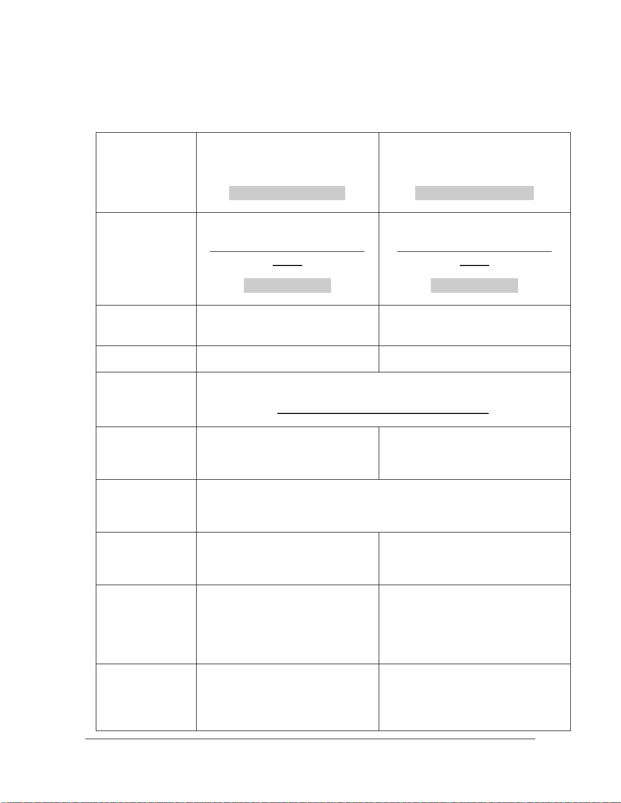
MODEL VLF AC HIPOT SPECIFICATIONS
VLF-4022CM ( 44kV,2.2µF)
Part No. VLF-1450S(120V)
Part No. VLF-1447S(230V)
VLF-6022CM (62Kv,2.2µf)
Part No. VLF-1423S (120V)
Part No. VLF-1439S (230V)
Input
120V,50/60Hz,10 A
Sinusoidal Power Required for full
output
230V,50/60Hz,6 A
120V,50/60Hz,15A
Sinusoidal Power Required for full
output
230V,50/60Hz,8 A
Output
Sinusoidal0-44kVacpeak,0.1,.05,and
.02 Hz frequency
Sinusoidal0-62kVacpeak,0.1,.05,and
.02 Hzfrequency
Duty
Continuous
Continuous
Test Capacitance
(Ins.Res.<10GΩ)
1.1 µF @ .1 Hz,2.2µF@ .05 Hz, 5.5 µf @ .02 Hz
Minimumcapacitancetoachievefulloutput-.01µF
Kilovoltmeter
3.5in., 0-45PEAK KILOVOLTS
2%Full-scale Accuracy
3.5in., 0-65PEAK KILOVOLTS
2%Full-scale Accuracy
Current/uFMeter
CM Models
3.5in.
0-100 PEAKMILLIAMPS,/5-0 uF,5% FS Accuracy
ControlCase Size
HighVoltageTank
22wx11dx15.25 high
14.5w x 10.5dx19high
26wx13d x16 high
15wx11dx21.5high
ControlCase Weight
HighVoltageTank
Weight
50lbs. (23kg)
72lbs. (33kg)
AccessoryBag10lb.(4.5kg)
75lbs. (34kg)
120 lbs. (54kg)
Intercon.cable
length
Outputcable length
10 ft.
RG8/U 20 ft.
10 ft.
ShieldedX-Ray 20ft.

OPERATOR MANUAL
-
7 -
Table 1 VLF SeriesSpecifications.
Figure 1 VLF-40 Series front panel controls
Figure 2 VLF-60 Series front panel controls

OPERATOR MANUAL
-
8 -
INPUT POWER
The INPUT POWER connector (if applicable) accepts most standard line/extension cords. The power
supplied to the input connector must be from a grounded Sinusoidal AC source rated to match the input
power specifications noted in Table 1.If extensions cords are used for the input, use 10 AWG cord for 25
ft, and 8AWG for 50ft cords. The output may not reach full voltage if the input extension is too small and
causesasignificant voltagedrop under power.
PLEASE NOTE- Using Square Wave Power Generators may reduce the maximum output of this
unit.
MAIN POWER
TheMAIN POWER pushbuttonswitchprovidesthepowertothecontrolandpowercircuits.Theneonlamp
in the switch will light when the power is on and voltage is available through input line cord. The INPUT
FUSE locatedelectricallybeforetheMAIN POWER switchprovides inputline protectionfortheunit.
EXT.INTLK (EXTERNAL INTERLOCK)
The Ext. Intlk. connector is provided to allow for a normally open safety interlock switch to control the
energizingofthehigh voltageoutput.
HV OVERLOAD
The HV OVERLOAD circuit breaker protects the variable transformer output control brush. Its thermal
characteristics allow for the short term overload of the variable transformer while still providing proper
protection.
HIGH VOLTAGE ON/OFF
The HIGH VOLTAGE ON (OFF) pushbuttons activate (de-activate) the high voltage power circuits. The
LED indicators provide long life positive indication of thecircuit status.The RED (ON) LED lights when high
voltage isenergized,theGREEN(OFF) LEDlightswhenthehighvoltageisde-energized.
OUTPUT CONTROL
The OUTPUT control variable transformer adjusts the output voltage. The 0-100 markings on the panel
indicate the low to high setting. The control must be at ZERO (0) to energize the high voltage circuits. The
output control must always be returned to zero at the completion of testing, prior to de-energizing
the output , allow the unit tocycle for 60seconds toassure full discharge ofthe load.
VOLTMETER
The KILOVOLT METER allows for accurate output voltage readings. 1-% precision resistors minimize the
need for re-calibration due to aging shift. See Voltmeter Re-calibration in Section 3 for details on
calibration.

OPERATOR MANUAL
-
9 -
SCOPE OUPUT
The SCOPE OUTPUT allows for accurate output voltage monitoring. This connector can be fed into an
oscilloscope for the looking at the actual output wave shape. The peak to peak voltage representing 40
kVacis8voltspeak/peak.(OntheVLF-6022,60kVacis6voltspeak/peak.)
OUTPUT FREQUENCY
The OUTPUT FREQUENCY switch adjusts between calibrated frequencies for testing loads larger than
normal .By allowing slower frequencies the output waveshape is maintained. Output frequency choices are
.1 Hz for 1.1 µF, .05 Hz for2.2 µF,and .02 Hz for5.5µF.
TIMER AND START TIMER PUSHBUTTON
The Timer is provided for tests when dwell time is important. The timer can be set from 1 second
increments up to hour increments. After the test has started, the timer can be started by depressing the
START TIMER pushbutton. The preset time will count down to zero. Upon reaching zero, the timer will
sound an alarm indicating the completion of the timing cycle. The timer will not shut down High Voltage. To
Resetthe timeralarm,withhighvoltageOFF,depresstheSTART TIMER pushbutton.
To set the H5CX Timer
1) Pressand hold ‘mode’ button for 3 seconds to enter program mode
2) Set the time range using the ‘up/down’ push buttons (default30min 00 sec)*
3) Set the timermode using the ‘up/down’ push buttons(default down)*
4) Set the timeroutputmode using the ‘up/down’ push buttons(default F)*
5) Set input signal width using the ‘up/down’ push buttons (default 20mS)*
6) Set keyprotect levelusing the ‘up/down’push buttons(UP-1)*
7) Pressand hold ‘mode’button for 3 seconds to exit programmode
*press ‘mode’ button briefly after adjusting each parameter to move to next step
CURRENT METER
CURRENT/CAPACITANCE METER
ThedualscaleCURRENT/CAPACITANCE meter provides for accurate output current monitoring. The
CURRENT portion of this circuit is for observing the charge and discharge currents in the cable load. 1%
resistors minimize the need forre-calibration due to agingshift. The CAPACITANCE scale is for measuring
the load cable capacitance (0-6uF/0-60uF) prior to test to determine the best operating frequency for that
particularcable run.
Note: The current meter on the VLF Series of AC hipot is for reference readings of current draw. The
current reading is affected by both frequency and cable length and as such is not appropriate for use in
trending orleakagemeasurements.
METER MODE
The METER MODE switch configures the current metering circuit for capacitance measuring or for output
currentmeasurement.
CAPACITANCE (PUSH TO READ X1) PUSHBUTTON

OPERATOR MANUAL
-
10
-
The PUSH TO READ X1 pushbutton changes the scale of the CAPACITANCE metering. The modified
Wheatstone Bridge incorporated in this circuit indicates x10 readings without depressing the PUSH TO
READ X1 pushbutton. When in the x10 scale and the reading is below 6
µ
F(0.6 on x10 scale), the PUSH
TO READ X1 shouldbe depressedtogetanaccurateload capacitance measurement.
CAP ZERO
This potentiometer is for zeroing the capacitance range at full scale prior to measuring the cable
capacitance.
CAPACITANCE MEASUREMENT POSTS
These posts are for connecting the cable to the capacitance measuring circuit. The HOT post is for the
cable center conductor, the COM postis for the cable's grounded shield.Be sure the cable is de-energized
before connectingthis lowvoltage circuit ordamage will result.The resulting capacitance measurement on
the cable will identify the best operating frequency for that particular cable run. A frequency table is
providedinthesectionOPERATING THE EQUIPMENT.
POS/NEG LED DISPLAY
TheseLEDs are toidentifyoutputpolarityasunit cycles.
DATA LOGGER
TheDATA LOGGER connectorisfortheexternalADL-1DataLoggeroption.
Note Regarding use of MCconnectors:
The MC connector requires the operator to push IN before pulling OUT to disconnect.

OPERATOR MANUAL
-
11
-
List of included componentswith the VLFHipot
Groundstick with20ft.ofgroundwire
Ext.Intlk.jumper plug
20ft.longoutputcable RG8/U;VLF-4022,20ft.longX-Raycable;VLF-6022
Alligator clipandhook terminations
10 ft.interconnect cable with grounds
BNC to BNC scopetopanel interconnectcoax cable
20ft.2AWG clearjacketed cable forsafety groundingof theHV section
Redand Black MeasuringLeads forCapacitiveLoadMeasurement
WARNING
DO NOT OPERATE THE VLF HIPOT SET IF THE HIGH VOLTAGE TANK IS 5
°
OR MORE FROM
LEVEL.
IF THE UNIT IS OPERATED OUT OF LEVEL, OVERHEATING AND INTERNAL ARCING MAY OCCUR.
DONOT STORE ORTRANSPORTVLF HIGH VOLTAGE SECTION
ON IT’SSIDE

OPERATOR MANUAL
-
12
-
SETTINGUPTHEEQUIPMENT
The setup of this equipment has been minimized by careful consideration of the operator during design.
TheVLF Series’ two-piece constructionallows for convenientportabilityfor ACtesting in the field.
Select a locationfor the unit that will allow easy viewing of the controlpanelat a safe distance from the
test object. Place the high voltage tank within 10 ft. of the control on a level area. The cooling and filter
assembly of the VLF series will not operate properly if the high voltage tank is placed on uneven ground. A
maximumangleforcorrectoperationis 5°.Blockingthetank to a levelconditionisacceptable.
1. Be sure that all the controls are off,in their de-energized or fully counterclockwise
position.
2. Secure the interconnect cable to the high voltage tank. Be sure the free-hanging
fan/pump connector is also connected tothe side connector.
3. Secure a ground test lead to the panel. TheGroundpost on the front panel should be
used for that purpose. A lead in the high voltage interconnect has been provided for the ground
connection.
4. Secure a ground test lead to HV TANK. TheGroundstud the top of the tank should be
used for that purpose. A 2 AWG CLEAR JACKETED lead has been provided for the ground
connection. The clampendshouldbeconnectedtoasolidearthground.
5. Connect theground stick to a solid earth ground.
6. Insert the coaxial output cable into the high voltage output connector on
the tank. Tightentheclampingnutsecurely.
7. When using a cable reel assembly with a VLF. Refer to “VLF Connection
Scheme with Cable Reel” in Operating the Equipment Section.
Note Regarding use of MCconnectors:
The MC connector requires the operator to push IN before pulling OUT to disconnect.
SECTION
2

OPERATOR MANUAL
-
13
-
8. Insert the EXT INTLK plug into the socket on the panel. The plug may also be
wiredtoanormallyopen contactofa safety switch for added protection.
The setup of the VLF AC Test Set does notaddress the need for proper safety grounding of the
load (test sample or cable). The grounding requirements vary for different types of tests.
Please consult the local codes where applicable or reference the guidelines for grounding
found under OPERATING THE EQUIPMENT.
WARNING
DO NOT OPERATE THE VLF HIPOT SET IF THE HIGH VOLTAGE TANK IS 5
°
OR MORE FROM
LEVEL.
IF THE UNIT ISOPERATED OUT OF LEVEL,OVERHEATING AND INTERNAL ARCING MAY OCCUR.
DONOT STORE ORTRANSPORTVLF HIGH VOLTAGE SECTION
ONITS SIDE
OPERATOR MANUAL
-
14
-
OperatingtheEquipment
This section provides step-by-step instruction on various test methods. Many facilities have their
own in-house test procedures, and this manual is not to supercede these. The purpose of this
sectionistoexplain thecapabilitiesof thistestsetinreal-worldapplications.
When testing cables, either single or three phase, there are certain extra steps that must be observed to
ensure safeoperation.
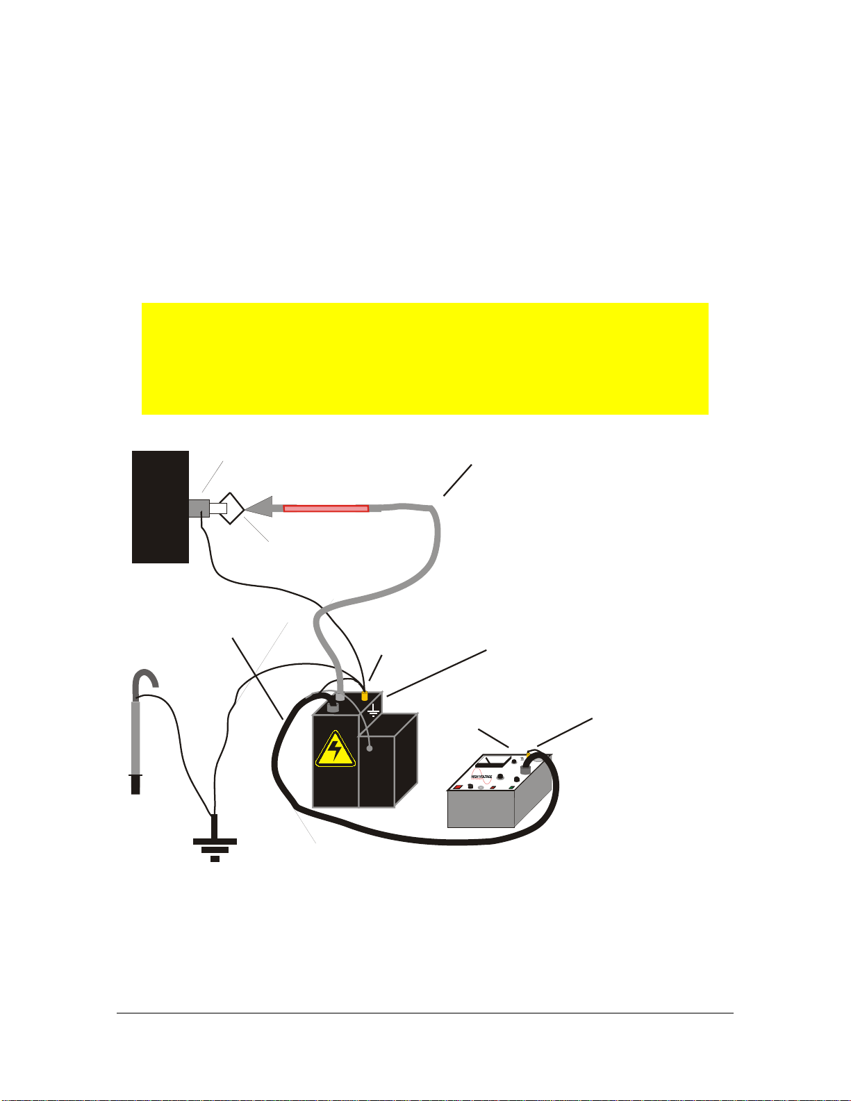
It should be noted that the VLF series test sets are not intended to be used
on vacuum bottles or switchgear without cables connected. The VLF requires
a minimum of .01uF load capacitance to achieve full output. If the
capacitance of the load is too low, the kilovolt meter will not read the actual
peak output and damage to theunit (and/or load) may result.
CONTROL
HV TA N K
INTER-CONNECT
CABLE
HV CABLE
(TEST O BJEC T)
O UTPUT C LIP
ORHOOK
HV OUTPUT
CABLE
VLFCONNECTION
SC HEME
TA N K G RO UN D
CONNECTION
CONTROLGROUND
CONNECTION
GROUND
STIC K

OPERATOR MANUAL
-
15
-
CONTROL
HV TANK
INTER-CONNECT
CABLE
VLF WITH C ABLE REEL
CONNECTION
SC HEM E
TANKGROUND
CONNECTION
CONTROLGROUND
CONNECTION
HIGHVOLTAGE
X-RAY C ABLE
GROUND
CABLE
LRO-40
CONNECTIONSTO
TEST O BJEC T
MC
CONNECTOR
ACTesting of High Voltage Cables
1. Ensure that all the steps listed in Setting Up the Equipment have been accomplished. Take
specialnotetogroundthecontrolsectionandthehigh voltagetanktoasolidearthground.
Caution!!
Before making any cable connections,ensure that the cable being
tested has been properly identified,de-energized, and
grounded!
2. Make sure thatall insulators,stresscones, andpot heads are cleanand free of moisture. This
willpreventflashoverandminimizeleakage.
3. Isolate the far end of the conductors under test for the test voltage; that may mean separating
someoftheconductorsinamulti-conductorcablefromeach otherand their shields.

OPERATOR MANUAL
-
16
-
The shields of all cables must be securely tied to ground at
the nearest end of the cable.
4. Anyconductorsorwiresinthecableorthevicinitynotbeingtested mustbegroundedto avoid
abuildupof chargeandpossibleshockhazard.
5. Voltage must be applied according to specifications from the cable manufacturer or any other
applicableteststandards
6. Prior to connecting anything to the test sample, be sure the test sample is identified, de-
energizedandgroundeduntilreadytotest.
7. First, the cable capacitance must be measured to determine the best operating frequency.
Placethecontrolnearthecablebeingtested.
8. Connect the input power terminal block (or cord) to a grounded, 50/60 Hz source as noted in
Table 1 Specifications. A generator is an acceptable power source. If extensions cords are
used for the input, use 10 AWG cord for 25 ft, and 8AWG for 50ft cords. The output may not
reach full voltage if the input extension is too small and causes a significant voltage drop
underpower.
9. Turn on the main circuit breaker. The MAIN POWER light will illuminate at both the power
section andthe control.
10. Operate the METER MODE to
µ
Fposition. Adjust the CAP ZERO for full scale deflection
(ZERO) on the meter.
11. Connect the HOT post to the center conductor of the test cable. Connect the COM post to the
groundedshieldofthetestcable.ReadtheCAPACITANCE scale(x10).
If the reading is below 6.0µF(0.6uF on scale) depress the x1 pushbutton. Then following table
provides operating frequencyversus capacitance.
Capacitance
Frequency
1.1µF orless
.1 Hz
2.2µF orless
.05Hz
5.5µF orless
.02Hz
A minimum load capacitance of 0.01μF is required to achieve full output of the VLF unit.
Other manuals for VLF-CM Series
1
This manual suits for next models
6
Table of contents
Other High Voltage Test Equipment manuals


Popular Test Equipment manuals by other brands


Sykes-Pickavant
Sykes-Pickavant SPe user guide

Berner
Berner 047894 operating manual

Höcherl & Hackl
Höcherl & Hackl PMLA Series user manual

Sensidyne
Sensidyne gilian gilibrator 2 Operation & service manual

JB INDUSTRIES
JB INDUSTRIES F6-BOOST operating manual

Extech Instruments
Extech Instruments 433201 user guide