High Voltage DTS-60A User manual

DTS-60A
DTS-100A
Dielectric Oil Test Set
Operator’s Manual
Manual Version 2.01
High Voltage
I C
.

DTS-60A / DTS-100A OPERATORS MANUAL
All rights reserved. Total or artial re roduction of this manual, whether by rinted or electronic means, is
forbidden. Information regarding any errors found in it or suggestions concerning im rovement are a reciated.
Since roducts are subject to continuous check and im rovement, High Voltage inc. reserves the right to make
changes in information contained in this manual without rior notification.
Manual Revision 4/6/2017 Version 2.01
Copyright 2016 High Voltage, Inc. – USA
HIGH VOLTAGE, INC.
31 County Route 7A
Copake, N.Y. 12516
Phone : (518) 329-3275
ax : (518) 329-3271
Web : http://www.hvinc.com
e-mail: [email protected]

DTS-60A / DTS-100A OPERATORS MANUAL
Icons & otation
This icon indicates danger conditions!
Danger!
This icon indicates warnings!
Warning!
This icon indicates a hint or a tip!
ote!
DTS-60A / DTS-100A OPERATORS MANUAL
This Operator manual contains instructions for the operation
of a High Voltage power source. The operator of this
equipment must use good judgement and follow all safety
precautions noted in this guide to ensure the protection of
themselves and others in close proximity to the test area.
Failure to follow the instruction could result in injury or
death.
Proper grounding of the test set must be done prior to
connecting this unit to a power source.

DTS-60A / DTS-100A OPERATORS MANUAL
Table of Contents
1. Specifications and Controls
1.1 Features and S ecifications
1.2 Control Panel
1.3 User Interface
1.3.1 Menu Overview
1.3.2 Key ad O erations
1.3.3 Warning Messages
1.3.4 Question Messages
1.3.5 Error Messages
1.3.6 Indicators
1.4 Setu the Equi ment
1.5 Startu the Equi ment
2. Menu/Submenus and Settings
2.1 Main O eration Overview
2.2 Main Menu
2.3 Settings Submenu
2.3.1 Time/Date Dialog
2.3.2 O erator Dialog
2.3.3 LCD Contrast Dialog
2.3.4 Language Dialog
2.3.5 Region Dialog
2.3.5 U date Firmware Dialog
3. Simple Test
3.1. Sim le Test O erations
3.2. Sim le Test Initialization
3.3. Sim le Test Controls
3.4. Sim le Test Execution
3.5. Sim le Test Termination
3.6. Sim le Test Exam le
4. Standard Tests
4.1. Standard Test Descri tion
4.2. Select a Standard Test
4.3. Standard Test Execution
4.4. Standard Test Exam le

DTS-60A / DTS-100A OPERATORS MANUAL
5. User Defined Tests
5.1. Test Descri tion
5.1.1 Test Structure
5.1.2 Test O erations
5.2. Select Test Menu
5.3. Scri t Files for User Defined Tests
5.3.1. Scri t File Commands and Arguments
5.3.2. Scri t File Test Exam les
6. History and Results
6.1. History Results
6.2. Exam le Using History Results
7. Printer and Printouts
7.1. Printer Descri tion
7.2. Changing the Pa er Roll
7.3. Printout Descri tion
8. Remote Operation
8.1. Remote O eration Descri tion and O eration
8.2. System Commands and Parameters
8.2.1 ver
8.2.2 cls
8.2.3 time
8.2.4 date
8.2.5 o erator
8.2.6 contrast
8.3 Test Commands
8.3.1. test list
8.3.2. test read
8.3.3. test delete
8.3.4. test erase
8.3.5 test download
8.4 Test Results Download Commands
8.4.1 history list
8.4.2 history read
8.4.3 history erase
Appendix I - Care and Maintenance
Appendix II - Example Test Program Script Files
Appendix III - Firmware Upgrade Procedure
Appendix IV - DTS Remote Operation Program

DTS-60A / DTS-100A OPERATORS MANUAL
1
Specifications and Controls
This section describes the s ecifications, controls, and features of the DTS-60A & DTS-100A
AC Dielectric Oil Test Sets.
Included in this section is a brief introduction about the equi ment’s set u and start u .
Features and S ecifications 1.1
Control Panel 1.2
User Interface 1.3
Menu Overview 1.3.1
Key ad O erations 1.3.2
Warning Messages 1.3.3
Question Messages 1.3.4
Error Messages 1.3.5
Indicators 1.3.6
Setu the Equi ment 1.4
Startu the Equi ment 1.5
1

DTS-60A / DTS-100A OPERATORS MANUAL
1.1 Features and Specifications
The DTS-60A & DTS-100A AC Dielectric Oil Test Sets rovide automatic, rogrammable, and
accurate measurement of breakdown voltage for insulating oils used in high-voltage electrical
equi ment.
Main features of the DTS-60A & DTS-100A Series of AC Dielectric Oil Test Sets
User Interface
Dot Matrix Liquid Crystal Dis lay (128x64)
Com act 5-key key ad for o eration
User friendly, menu driven functionalities
Large out ut voltage dis lay
Functionalities
Test Result storage and re orting
Real Time Clock
Ambient Tem erature measurement
International Standard Tests
User Defined Tests
Language selection
Measurements and Control
High accuracy of High Voltage measurement (0.5%)
Digitally selected Voltage rate of rise (0.1kV/s ste )
Arc detection with less than 5 milliseconds shutdown
Digital Closed-Loo for voltage control
Equipment Case
Rugged aluminum case
Window for observation of oil test
2

DTS-60A / DTS-100A OPERATORS MANUAL
Table 1.1 - S ecifications
DTS-60A & DTS-100A unless otherwise indicated
Input 120V, 50/60 Hz, 5 am s, single hase
230V, 50/60 Hz, 3 am s, single hase
Output DTS-60A: 0 – 60kVac, 800VA resistive load, between bushings
DTS-100A: 0 – 100kVac, 800VA resistive load, between bushings
Output Termination Dual Ca acitively Graded Bushings
Display Dot-Matrix 128x64
Keypad 5 keys for equi ment’s functionalities
Printer 40 column dot-matrix
Remote Operation RS-232 Serial Interface or USB HID Serial Interface
Breakdown Shutdown Less than 5 ms
Accuracy 0.5%
Operating Temperature -14F to 104F (-10C to 40C)
Case Size 14.75w x 14d x 11.5h in (36.88w x 35d x 28.75h mm)
H.V. Tank High Voltage Tank Included
Weight 60 lbs.
3
DTS-60A / DTS-100A OPERATORS MANUAL
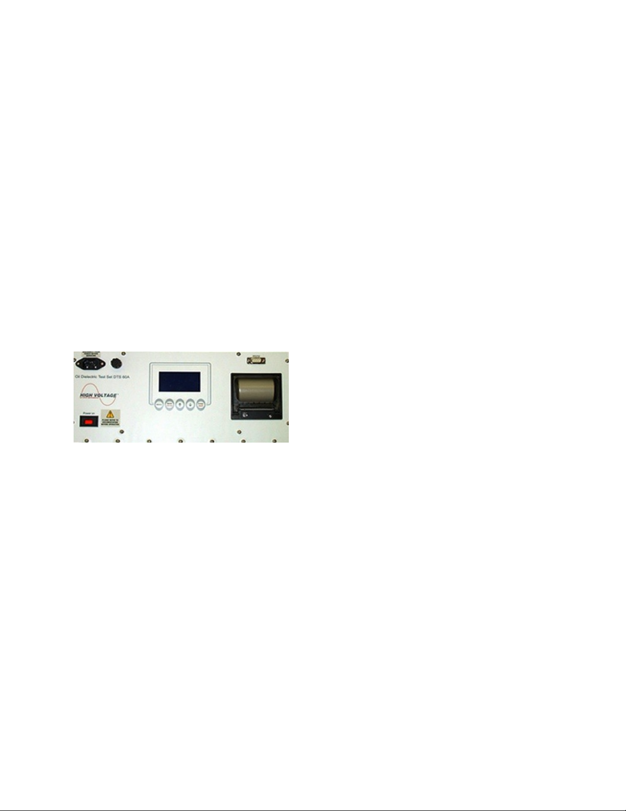
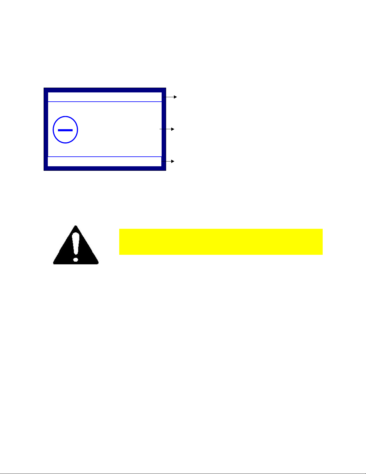
1.2 Control Panel
The equi ment’s Control Panel is de icted in Figure 1.1. It consists of the following:
Input Power Connector
The In ut Power connector acce ts most standard electrical equi ment ty e
cords. The ower su lied to the in ut connector must be from a grounded
source rated to match the in ut ower s ecifications noted in Table 1.1.
Main Power Switch
The Main Power switch rovides the ower to the control and ower circuits. The
neon lam will light when ower is on and voltage is available through the in ut
line cord. The In ut Power Fuse, located electrically before the Main Power
switch, rovides line fault rotection for the unit.
Fuse Socket
LCD Display
The Liquid Crystal Dis lay guides the user to the system’s functionalities.
Keypad
Com act 5-key key ad for equi ment o eration.
Printer
Dot Matrix rinter for o tionally out utting results from the current test, or from
the stored history of the last fifty tests erformed.
Figure 1.1 – DTS-60A / DTS100A Control Panel
4
DTS-60A / DTS-100A OPERATORS MANUAL
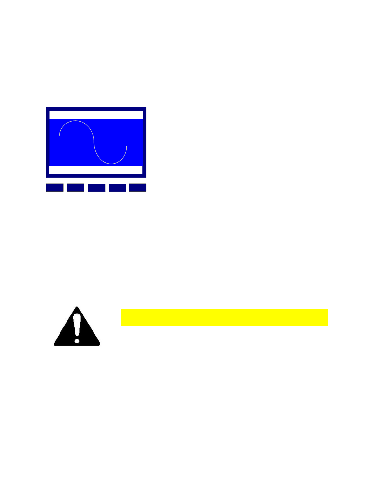
1.3 User Interface
The Equi ment User Interface is based on a dot-matrix Liquid Crystal Dis lay (LCD) and a
com act 5-key key ad, shown in Figure 1.2. The user-friendly gra hical interface makes the
equi ment's o eration sim le and attractive.
Figure 1.2 – Equi ment User Interface
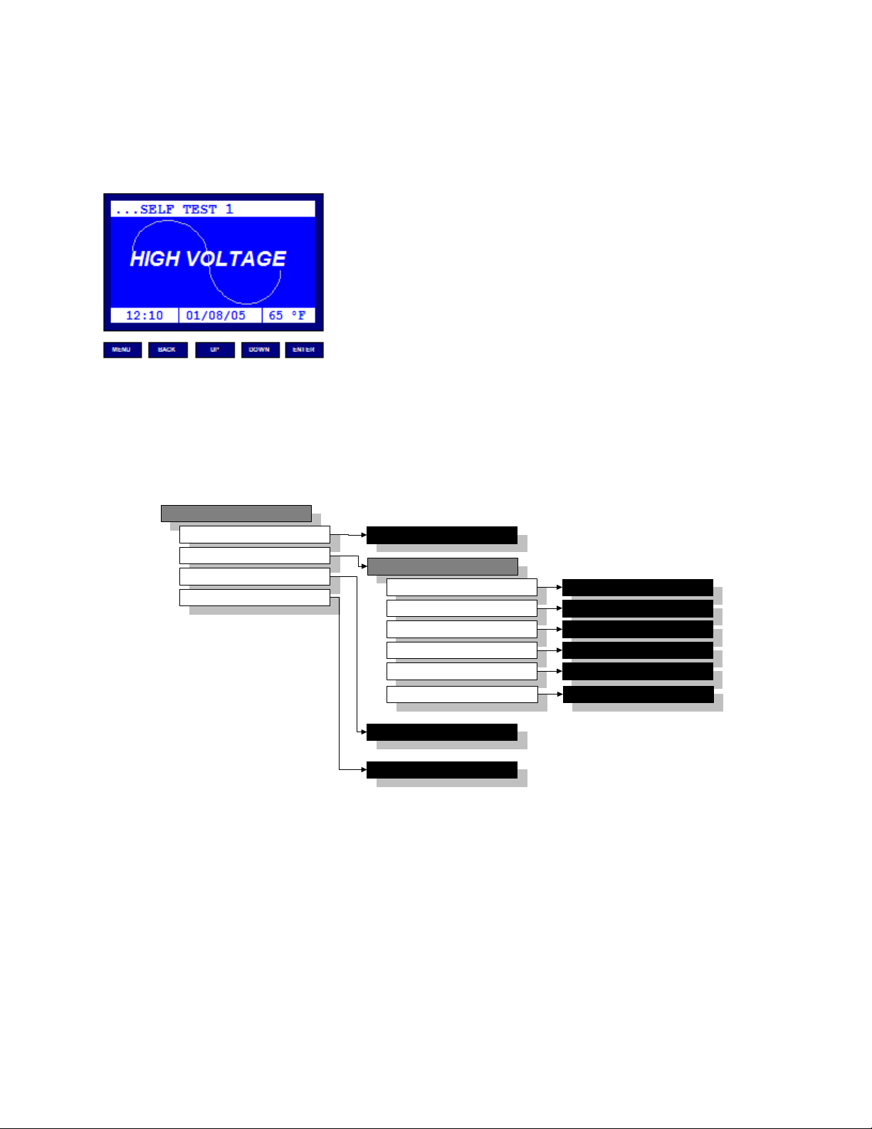
1.3.1 Menu Overview
The equi ment o eration is based on a user friendly structure of menu/submenu driven
functions. An overview of the menu/submenu selections is summarized in Figure 1.3.
Figure 1.3 – DTS-60A & DTS-100A User Interface
5
MENU
SELECT TEST
SETTINGS
TEST HISTORY
REMOTE OPERATION
SETTINGS
TIME/DATE
OPERATOR
LCD CONTRAST
LANGUAGE
TEST HISTORY APP
REMOTE OPERATION APP
SELECT TEST APP
SETUP TIME/DATE APP
SETUP OPERATOR APP
SETUP LCD CONT. APP
SETUP LANGUAGE APP
REGION SETUP REGION APP
UPDATE FIRMWARE UPDATE FIRMWARE APP

DTS-60A / DTS-100A OPERATORS MANUAL
1.3.2 Keypad Operations
The DTS-60A and DTS-100A use a ty ical lcd/key ad interface in which the actions of the keys
are defined by the ty e of menu or a lication dialog that is active. The most common ty es
are listed below. Any s ecial key functionality for a given dialog are detailed later in the
manual.
Simple Test Operations
ME U Proceed to the Main Menu before/after test
BACK Enable/Disable Stirrer (before stage begins)
Select "No" for rom t
UP Increase Voltage Rate of Rise
Pick "Yes" rom t
DOW Decrease Voltage Rate of Rise
Pick "No" rom t
E TER On Entry, Execute Sim le Test
Begin Test Stage with chosen voltage rate
Select "Yes/No" rom t
A Y After Starting the Test ANY key interru ts the rocess
Standard and User Defined Test Operations
ME U Proceed to the Main Menu before/after test
BACK Select "No" for rom t
UP Pick "Yes" rom t
DOW Pick "No" rom t
E TER Execute Standard or User Defined Test Test
Select "Yes/No" rom t
A Y After Starting the Test ANY key interru ts the rocess
Main Menu and Submenu Operations
BACK Exit from Main Menu to Test O erations
Exit from Submenu to Main Menu
UP Move U to the revious selection
DOW Move Down to the next selection
E TER Proceed to the selection
umber Edit Operations
BACK Discard changes and return
UP Increase the current value
DOW Decrease the current value
E TER Enter the value
Operator String Edit Operations
ME U Choose Character Set: u er case; lower case; numbers; symbols
BACK Delete Character
UP Select revious character, wait 3 seconds to enter individual character
DOW Select next character, wait 3 seconds to enter individual character
E TER Enter the com leted string
6
DTS-60A / DTS-100A OPERATORS MANUAL
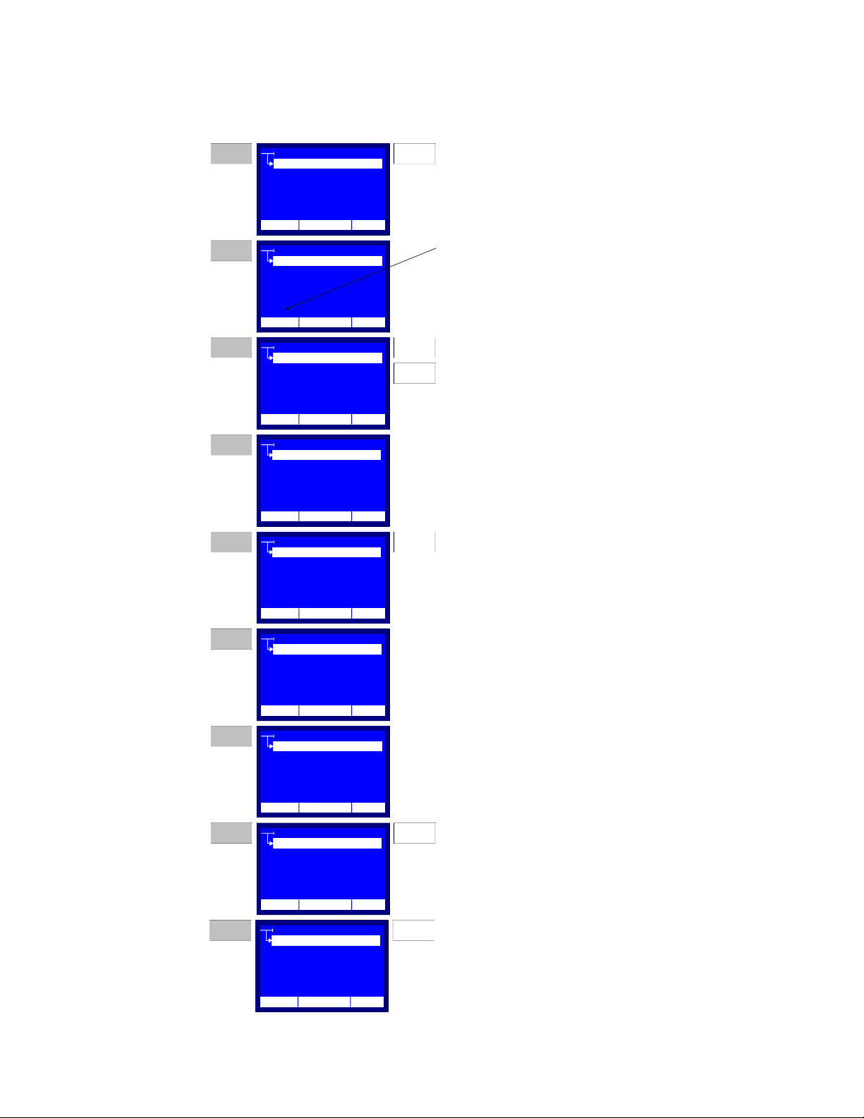
Figure 1.4 illustrates the O erator String Edit O eration. The exam le refers to a string entry
for the O erator Name (see section 2.3.2).
Figure 1.4 – String Entry Key ad O eration
7
OPERATOR
12:10 01/08/16 25 C
NAME
COMPANY
CONTACT INFO
OTHER INFO
Press the ENTER key in rder t enable the String
Entry keyb ard perati n f r the Name
OPERATOR
CONTACT INFO
OTHER INFO
_
STEP 1
The String Entry Curs r is displayed. This
indicates the current p siti n f the editable
character.
OPERATOR
CONTACT INFO
OTHER INFO
O
Use the UP and DOWN keys t select the desired
character. D nt leave m re than 3 sec nds
between key pressings. After every UP key
pressing the next character f the alphabet will be
displayed. In c ntrast, after every DOWN key
pressing the previ us character f the alphabet will
be displayed. The character sequence is circular.
OPERATOR
CONTACT INFO
OTHER INFO
O_
St p pressing the UP and DOWN keys f r m re
than 3 sec nds. The character will be entered and
the curs r will be displayed in the next p ssiti n.
STEP 2
STEP 3
STEP 4
ENTER
UP
DOWN
OPERATOR
CONTACT INFO
OTHER INFO
_
A mistake ccured! Press the BACK Key in rder
t delete the last entried character.
OPERATOR
CONTACT INFO
OTHER INFO
P_
Select the c rrect character acc rding STEP 3
instructi ns. Then wait 3 sec nds, until the curs r
is displayed at the next p siti n.
OPERATOR
CONTACT INFO
OTHER INFO
PETER_
Repeat the character entry perati n f r the wh le
string.
OPERATOR
CONTACT INFO
OTHER INFO
PETER_0
Press the MENU key twice, in rder t ch se the
numeric character set.
The character sets r tate in rder:
upper case
l wer case
numbers
symb ls
STEP 5
STEP 6
STEP 7
STEP 8
BACK
MENU
COMPANY
COMPANY
COMPANY
COMPANY
COMPANY
COMPANY
COMPANY
NAME
NAME
NAME
NAME
NAME
NAME
NAME
12:10 01/08/16 25 C
12:10 01/08/16 25 C
12:10 01/08/16 25 C
12:10 01/08/16 25 C
12:10 01/08/16 25 C
12:10 01/08/16 25 C
12:10 01/08/16 25 C
OPERATOR
CONTACT INFO
OTHER INFO
PETER_007
Press the ENTER key in rder t enter the edited
sting and return.
STEP 9 ENTER
COMPANY
NAME
12:10 01/08/16 25 C

DTS-60A / DTS-100A OPERATORS MANUAL
1.3.3 Warning Messages
The LCD dis lay will show a warning message in the following cases:
1. Lid is Open, Figure 1.5.
This warning message is dis layed when the Lid of the equi ment is o en while a
test is running. The current o eration (i.e. test execution) will be restarted when the
lid is closed.
Warning Message
Lid is Ope
SYSTEM HALTED...
TEST:ASTM D1816/84
12:10 01/08/16 65°F
TIMER:00:00:00
Figure 1.5 – ‘Lid is o en' Warning Message for Standard Test ASTM-D1816/84
If the Warning Message “Lid is Open” is depicted when
the Lid is closed, contact the distributor or the
manufacturer.
8

DTS-60A / DTS-100A OPERATORS MANUAL
2. Verify Electrode/Gap Spacing, Figure 1.6a/b.
This warning message is dis layed at the startu of every test rocedure, in order to
remind the user to check the electrodes ty e and s acing, according to the selected
test. If the selected test is a Standard Test or User Defined Test one (where the
s acing and the ty e of the electrodes is s ecific) the message will inform the user
for the a ro riate settings (ty e, s acing), Figure 1.6a. The user may roceed by
ressing the ‘E TER’ key.
Warning Message
TEST READY...
TIMER:00:00:00
TEST:ASTM D1816/84
Electrodes:
Spacing:0.04in
ENTER > PROCEED TEST
Figure 1.6a – ’Electrodes/ S ace’ Warning Message
If the selected test is the Sim le Test (where the s acing and the ty e of the
electrodes is not s ecified) the message will remind the user to verify the desired
electrode ty e and s acing, Figure 1.6b. The user may roceed by ressing the
‘E TER’ key.
Warning Message
MENU > GO TO MENU
TEST:SIMPLE TEST
VOLTAGE: 0.5 kV/s
TIMER:00:00:00
Verify Electrodes
Figure 1.6b – Verify Electrode/Ga S acing’ Warning Message
9

DTS-60A / DTS-100A OPERATORS MANUAL
1.3.4 Question Messages
The unit may dis lay the following Question Messages.
1. Continue Test?, Figure 1.7.
This question message is dis layed during the Sim le Test after a breakdown has
been detected. The o erator is rom ted with a "Yes/No" rom t. Use the 'UP' key
to select the "Yes" icon or use the 'DOW ' key to select the "No" icon.
In this dialog, choosing the "Yes" icon will set u a new test stage and choosing the
"No" icon will sto the Sim le Test and roceed to the Print Results Question
Message.
Press the 'E TER' key to make your choice.
?
Questi n Message Sh wing "Yes" Ic n Selected
TEST:SIMPLE TEST
VOLTAGE: 0.5 kV/s
TIMER:00:00:00
12:10 01/08/16 65°F
Continue
Test?
YES
Figure 1.7 – ‘Continue Test?’ Question Message
2. Print Results?, Figure 1.8.
This question message rom ts the user for rinting the test results after a test is
finished. Similar to the "Continue Test" message, use the 'UP' and 'DOW ' keys to
choose the "Yes" icon or the "No" icon.
Press the 'E TER' key to make your choice.
?
Questi n Message Sh wing "N " Ic n Selected
TEST:SIMPLE TEST
TEST RESULTS
NUM. BD: 5
12:10 01/08/16 65°F
Print
Results?
NO
X
Figure 1.8 – ‘Print Results?’ Question Message
10
DTS-60A / DTS-100A OPERATORS MANUAL
1.3.5 Error Messages
Error messages indicate serious equi ment malfunction. The system can dis lay the following
Error Code/Messages, Figure 1.9:
Error 100, Error 101, Error 102, Error 110, Error 111
Error 112, Error 113, Error 120, Error 121, Error 122
Err r C de
Err r Message
User Interface Help Message
ERROR: 102
C ntact
High V ltage Inc.
f r m re inf rmati n...
+1 518-329-3275
12:10 01/08/16 65°F
Figure 1.9 – Error Message
Whenever you see an ERROR message, contact the
distributor or High Voltage, Inc.
11

DTS-60A / DTS-100A OPERATORS MANUAL
1.3.6 Indicators
Dis lay shows the following Indicators, in the following cases, Figure 1.12a/b.
1. Current Stage Indicator
This indicator notifies the user for the current stage of a test rocedure.
2. High Voltage On/Off Indicator
This indicator notifies the user for the status of the high voltage tank.
If the indicator is dis layed, the high voltage is ON.
3. Stirrer Indicator
This indicator notifies the user for the status of the stirrer.
If the indicator is dis layed the stirrer is ON.
4. Breakdown Blinking Indicator
After a test stage, this blinking indicator notifies the user that a breakdown was
detected.
TEST:ASTM D1816/84
TIMER:
00:00:02
kV
STIR
HV ON
Stirrer n/ ff indicat rHigh V ltage On/Off Indicat r
Current Stage Indicat r
STAGE
3
0.5kV/s > BREAKDOWN
01.0
12:10 01/08/16 65°F
Figure 1.12 – Indicators during a test stage: high voltage ON; stirrer ON; test stage 3
TEST:ASTM D1816/84
TIMER:
00:00:05
kV
STIR
Stirrer n/ ff indicat r
Current Stage Indicat r
STAGE
7
AFTER BD WAIT TIMER...
35.2
12:10 01/08/16 65°F
BD
BreakD wn Blinking Indicat r
Figure 1.12 – Indicators after breakdown detected: high voltage OFF, stirrer ON; BreakDown detected; test stage
7; After BreakDown Timer counting down.
12

DTS-60A / DTS-100A OPERATORS MANUAL
1.4 Setup the Equipment
The setu of this equi ment has been minimized by careful consideration of the o erator
during design. The DTS-60A and DTS-100A one- iece construction ermits convenient
ortability. The test set requires that the unit is o erated with the control anel in the
horizontal osition, in order to kee oil level over high voltage transformer in the high voltage
tank.
1. Select a location for the unit that will allow easy viewing of the LCD dis lay
2. Be sure that all the controls are off, in their de-energized state.
3. Remove all components and oil vessels from the test chamber
4. Install the input line cord into the Input Power rece tacle
5. Connect the line cord to a suitable (120V or 230V, see Specifications
Table) grounded power source.
6. Select the desired Test cell. Fill in with sufficient oil for the testing to be
erformed.
7. Clean the Test Cell and Electrodes thoroughly and adjust the electrodes to
conform with the ro er ASTM S ecification. Be sure the electrodes are securely
tightened on the adjustment osts inside the oil vessel.
Use Isolation transformer (1/1) if the electrical
installation has neutral earthing.
All the oil vessels designed and made by High Voltage Inc. have
interchangeable posts and electrodes. These oil vessels were designed to
conform to the ASTM test specifications requiring simple disassembly for
cleaning. This design greatly reduces the time and effort required keeping
your oil vessels in top operating condition.
The operator of this equipment must use good
judgement and follow all safety precautions noted in
this guide to ensure the protection of himself and others
in close proximity to the test area. Failure to follow the
instructions could result in injury or death.
13
DTS-60A / DTS-100A OPERATORS MANUAL
1.5 Startup the Equipment
1. Ensure that setu has been com leted as described in section 1.4, Setu the
Equi ment.
2. Turn on Main Power.
3. The equi ment initiates a self-test, Figure 1.13. The Firmware Version is shown, then
the Self Tests begin executing. In case of malfunction, an error message is dis layed
and the system will be halted (see section 1.3.5).
...SELF TEST 1
MEN U B AC K D OW NU P ENTER
INC
TM
HIGH VOLTAGE
12:10 01/08/16 65°F
Figure 1.13 – Startu and Self Test
4. After the self-tests are com leted, the last selected test is resented: Sim le Test;
Standard Test; or User-Defined Test.
5. The unit will dis lay the Electrode Warning message and will wait for ‘E TER’ to be
ressed to start the test(see section 1.3.3).
6. Before starting a test the user may o en the lid, check the electrodes (ty e and
s acing) and finally fill the a ro riate test vessel with insulating oil. After closing the
lid, the user should ress the ‘E TER’ key to start the test.
Whenever you see an ERROR message contact the
distributor or High Voltage Inc. directly.
14
Other manuals for DTS-60A
1
This manual suits for next models
1
Table of contents
Other High Voltage Test Equipment manuals


