Highland Tank Passive Grease Interceptor User manual

User’s Manual
Installation, Operation & Maintenance
Carefully read and follow the instructions in this manual.
Passive
Grease
Interceptors
Single, Double &
Triple-basin
Proudly made
in America
814.893.5701 | highlandtank.com
Highland Tank
count on our products. trust in our people.
grease i
nterceptors
HT-2816

2 • www.highlandtank.com
Warning and Disclaimer
This manual is intended for use only by persons knowledgeable
and experienced in underground grease interceptor installation,
operation and maintenance. This manual provides general guidance, and
conditions at your site may render inapplicable some or all of the guidance. If
you are uncertain, or require clarication or further instruction, please con-
tact Highland Tank prior to commencing any installation, operation or main-
tenance procedure. You are solely
responsible for compliance with all federal, state and local laws,
regulations and ordinances applicable to your installation and
operation. Highland Tank disclaims all liability related to any misuse of the
tank or failure to follow all guidance and instruction provided by Highland
Tank.

www.highlandtank.com • 3
Installation 6
Piping & Venting 15
Start-up 20
Operation 21
Maintenance 24
PGI Reference Diagrams 27
Options and Accessories 29
Best Management Practices 30
Thank you for purchasing a Highland Tank Grease Interceptor -
the leading high-performance interceptor in the industry.
The purpose of this manual is to provide detailed information
on the installation, venting, startup, operation, inspection,
maintenance, trouble-shooting and best management practices for the
Highland Tank Passive Grease Interceptor.
These instructions should be used in conjunction with any
and all other applicable installation and corrosion protection
system instructions, e.g.:
• Highland Tank’s HighGuard Tank Installation Instructions,
HT-7001,
• Steel Tank Institute ACT-100-U® Installation Instructions,
R971.
Note: This manual is based on Highland Tank’s standard grease in-
terceptor congurations. Other custom congurations are available.
Verify the supplied conguration prior to installation and testing.
Appendix A: Best Management Practices (print and post) 30
Appendix B: Aboveground Interceptor Installation 31
Sample Inspection/Maintenance Log 33
Grease Hauler Manifest 35
No Grease sign (print and post near sinks and drains) 36
PGI - Passive Grease Interceptor
BMP - Best Management Practices
FOG - Fats, Oil & Grease
FSE - Food Service Establishment
AHJ - Authority Having Jurisdiction
Contents
Introduction
Appendices
Forms
Glossary of Terms

4 • www.highlandtank.com
Important points to consider prior to installation, operation and maintenance of the PGI:
Carefully read and follow instructions in this manual. Local codes and ordinances may apply.
Check with local AHJ prior to installation of PGI.
• Ensure adequate site space - almost all products are delivered on a 75-foot-long
tractor trailer. Allow space for unloading, positioning and temporary storage if
applicable.
• Ensure the crane has adequate lifting capacity and clearance - have operator check
site for clearances (overhead, turning, etc.). Spreader bars may be required for 10
foot diameter and larger PGIs.
• PGIs that are 0 foot diameter and larger are typically shipped rotated to minimize
over-the-road height. They must be lifted from the hauling trailer by the supplied
lifting lugs on the heads of the PGI. They must then be rotated before nal lifting
into the excavation. Spreader bars and/or adequate lifting straps must be available
to maintain recommended safe lifting capacity. Please check approval drawing for
overall length of the PGI and location of the head lifting lugs.
• Do NOT rotate the PGIs while they are still on the trailer - damage may result. PGIs
must be lifted from the trailer, using the lifting lugs supplied on the heads, and
lowered onto a at area, free from anything that may cause damage to the exterior
coating. Once the PGI is stable, the lifting device may need to be repositioned and
then reattached to the lifting lugs on the top centerline of PGI. At this point, slowly
roll the PGI to upright position on the ground before lifting to place in nal resting
position.
• Special permits may be required for weight, size, etc. by local code or ordinance.
• Conrm inlet/outlet piping elevations - coordinate with site plan - check/recheck
approval drawing when PGI arrives.
The Highland Tank PGI is designed specically for the separation of
fats, oils, grease and settleable solids from commercial and industri-
al food service facilities. The PGI intercepts and collects these pol-
lutants from the facility’s waste stream and prevents their discharge
into the environment.
The PGI is a stationary, wastewater treatment tank lled with water.
Internal bafes and weirs diffuse ow and create an extended path
for FOG to contact static water in the tank. Initial solids separation
and knockout occur in the rst chamber and are retained by means
of a sludge bafe. Sizing of a PGI is based on the GPM ow to unit.
PGIs retain waste stream inuent long enough to allow FOG to
separate from waste stream and rise to surface. Retained FOG
cools, solidies and remains in the PGI until removal.
Standard PGI
Description

www.highlandtank.com • 5
Important points to consider (continued):
• Make sure PGI hold-down method/system is predetermined and components are at
the site prior to PGI installation.
• Never enter the PGI or any of its enclosed spaces without proper conned space
entry training and approved equipment. See OSHA, Regulations for Permit-Required
Conned Spaces - 29 C.F.R. § 1910.146.
• Barricade the PGI installation area until job is complete.
• The PGI will not remove chemical or physical emulsions, dissolved hydrocarbons,
solvents or Volatile Organic Compounds. Avoid introducing such materials into the
PGI.
• Waste oils, such as frying oil, should not be intentionally drained into the PGI.
Filling the PGI with waste oils adversely affects PGI performance. Waste oil should
be properly disposed of by other means.
• The PGI needs to be maintained to remain as free of accumulated FOG and solids as
possible. Suction removal of waste as needed, is the best and recommended
method of maintenance.
• The location of your PGI should be as close as possible to the source of the FOG to
minimize solidication in the piping system. PGI must also be placed in an area with
sufcient truck access (top-side clearance) for waste removal.
• An absence of gravity ow to the PGI will necessitate wastewater pumping. Pumping
should be restricted to the clean water, efuent end of the PGI. If pumping occurs at
the inuent end, it will mix the grease and water, increasing the emulsied and
dissolved grease content and possibly causing PGI failure. If a pump is installed
upstream of the PGI, it must be a positive displacement pump (e.g. progressive
cavity, diaphragm, sliding shoe), set at minimum ow rate and installed as far
upstream as possible to minimize grease/water mixing.
• Piping should be designed to minimize turbulence and promote laminar ow.
• The PGI must be kept from freezing at all times. The PGI and piping should be
installed below local frost levels. If necessary, a thermostatically controlled steam
or electric heating device may be installed.
• Fill the PGI with clean, fresh water before introducing any wastewater. Complete the
PGI Installation Checklist and Start-up Report (Form # HT-9049). A copy of the
completed form should be retained by the PGI owner and installation contractor.
• Complete the HighGuard or ACT-100-U® Installer Information Card that was included
with the delivery documents. This information is required to activate and maintain
the Limited Warranty.
6 • www.highlandtank.com
PGIs must not be dropped, dragged or handled with sharp objects
and, except as minimally necessary for inspection and testing,
should not be rolled. Lifting equipment must be of adequate size to
lift and lower the PGI without dragging, dropping or damaging the
PGI or its coating.
The PGI must be mechanically unloaded. Use extreme care when
unloading as weight distribution of PGI may be uneven.
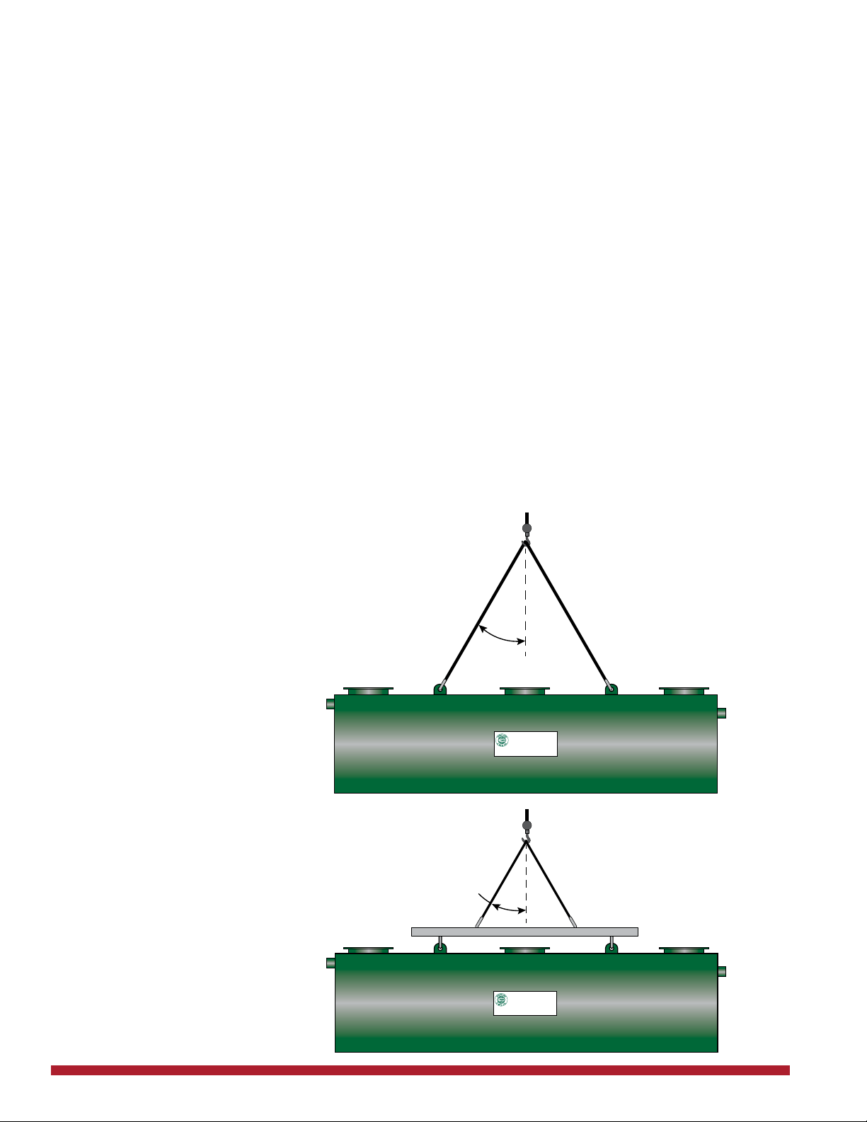
Lifting and moving the PGI must only to be done using the lifting
lugs welded to the PGI. PGIs should be carefully lifted, moved and
lowered using cables, chains or straps of adequate size. When two
lifting lugs are used, the angle between the lifting cable and vertical
shall be no more than 30 degrees. See Fig.1. Use a spreader bar
where necessary. Maneuver PGIs with guidelines attached to each
end of the PGI. If PGIs must be relocated on a job site during
installation, they must be lifted and not rolled.
Care in Handling PGIs
PGI Unloading
Lifting and Moving
WARNING:
Under no circumstance
should chains or slings be
used around
the PGI shell.
Fig. 1
Installation
Max. 30º
Use spreader bar
when necessary
Max. 30º
HighlandTank
HTM-0001
www.highlandtank.com
®
Installation & Maintenance Instructions are available at www.highlandtank.com
HighlandTank
HTM-0001
www.highlandtank.com
®
Installation & Maintenance Instructions are available at www.highlandtank.com

www.highlandtank.com • 7
Upon delivery, visually inspect the PGI for exterior damage that may
have occurred during shipping or job site handling. Any damage that
could result in leakage or corrosion must be repaired in a manner
approved by Highland Tank. Please refer to coating repair instruc-
tions below. If a PGI is not buried within 90 days, the PGI should be
covered to protect the exterior coating from the effects of ultraviolet
light damage.
If the PGI is of double-wall construction and has shipped with a
vacuum drawn on the interstice, inspect the vacuum gauge. If the
gauge indicates less than 5 inches, reinstitute the vacuum to 7
inches. Maintain 5 inches of vacuum for 2 hours before installing the
PGI. Do not relieve pressure until PGI is secured in its nal resting
position.
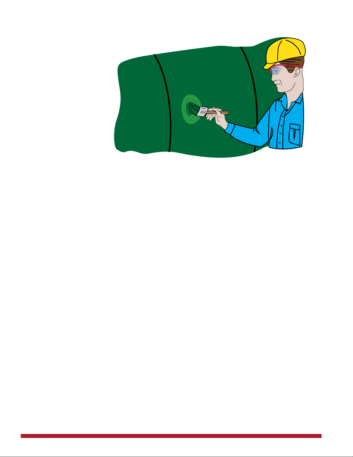
Before placing the PGI in the excavation, all dirt clods and foreign
matter shall be cleaned from the surface of the PGI. Damage to
coating surface must be repaired using the supplied touch-up kit.
Visually inspect the PGI for damage. Pay particular attention to areas
where coating may have been gouged or abraded. Mark all areas
which appear damaged for repair.
Clean damaged PGI coating areas of rust, contaminants or
disbonded coating prior to application of touch-up coating.
Areas of coating damage shall be roughened up with coarse grit
sandpaper or grinder (see Society of Protective Coatings (SSPC)
SP-2 “Hand Tool Cleaning” or SP-3 “Power Tool Cleaning” for addi-
tional guidance) to remove all glossiness from the surface surround-
ing the repair area approximately 6 inches around the damaged
area. Re-coat the area with touch-up coating provided. See Fig. 2.
Allow the repaired coating areas to cure completely.
Damaged polyurethane coatings must be repaired with the
polyurethane repair kit that was delivered with the PGI.
Carefully remove manway covers so as not to damage the gaskets.
Inspect the interior of the PGI from above (without entry) to ensure
that internal piping is secure and has not been damaged during
transport. Do not allow anyone to enter the PGI unless it has been
properly prepared for entry and the person entering the PGI has
been properly trained for conned-space entry per OSHA, Regula-
tions for
Permit-Required Conned Spaces - 29 C.F.R. § 1910.146.
DO NOT ENTER the PGI without following proper conned space
entry procedures.
Pre-Installation
Inspection & Testing
Coating Repair
Internal Piping
Inspection
WARNING:
8 • www.highlandtank.com
After repairs have been completed, all repaired areas of the
HighGuard and ACT-100-U® protection system coatings shall be
re-tested with a holiday detector set at 15,000 volts.
Fig. 2Coating Repair
(continued):

www.highlandtank.com • 9
Slope of excavation
determined by soil
type and/or code.
Consult AHJ.
Remove all large and sharp rocks/debris from
excavation prior to lowering PGI into position.
24" Minimum
12" Minimum - Clean inert sand,
pea gravel or crushed stone
The excavation should provide adequate space for the PGI(s)
piping and associated equipment. It must also be free of any
hard or sharp material that could cause damage to PGI
coating.
Be certain that foreign matter is not introduced into the
excavation or backll.
The total depth of the excavation is determined by the PGIs
diameter, bedding thickness, hold-down pad (if required) depth of
cover (including any effects of vehicular trafc) and slope and length
of piping. Consult AHJ for additional requirements related to existing
structures.
DO NOT exceed maximum burial depth as predetermined
by manufacturer.
Bedding and backll must be a homogenous material
consisting of compacted clean sand, pea gravel, No. 8 crushed
stone (American Society of Testing and Materials - ASTM-448) or
equivalent. (100% through a 1/2 inch (13 mm) sieve and no more
than 12% by dry weight through a #200 sieve (0.0029 Inch (0.0754
mm)). Pea gravel shall be no larger than 3/4-inch (19 mm). See Fig.
3.
Excavation and
Bedding
Fig. 3
CAUTION:

10 • www.highlandtank.com
Excavation and
Bedding
(continued):
Fig. 4
Slope of excavation determined by
soil type and/or code. Consult AHJ.
Remove all large and sharp rocks/debris from
excavation prior to lowering PGI into position.
24" Minimum
HighlandTank
HTM-0001
www.highlandtank.com
®
Installation& Maintenance Instructions are available at www. highlandtank.com
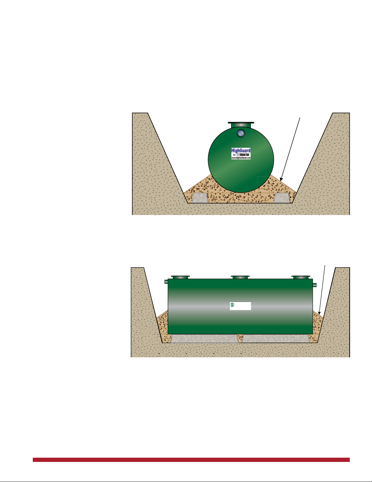
The bottom of the excavation must be covered with bedding
material to a minimum depth of one foot, suitably graded and lev-
eled and extend at least two feet around the perimeter of the PGI for
backll operations. Place at least 24 inches of backll between any
adjacent PGIs, tanks and excavation walls. See Fig. 4.
Placement of the PGI The PGI must be installed in a level and plumb position.
Check elevations at each end of the PGI with a transit and adjust as
necessary to 1/2 inch in 20 feet. Check elevations across the diame-
ter of the PGI and adjust to 1/4 inch in 10 feet.
www.highlandtank.com • 11
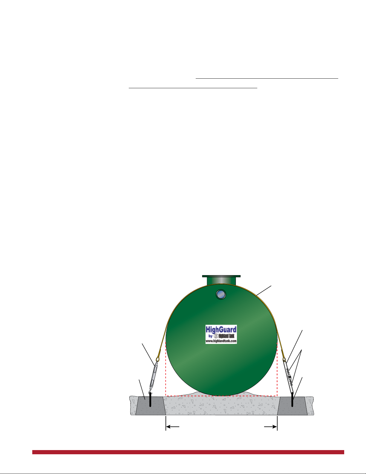
Anchoring High water tables or partially ooded excavation sites exert
signicant buoyant forces on PGI. Buoyant forces are partially resist-
ed by the weight of the PGI, the backll and any pavement atop the
PGI. Additional buoyant restraint, when required, is obtained by us-
ing properly designed hold-down straps in conjunction with concrete
hold-down pads or deadman anchors. The use of steel cable and/or
round bar as buoyant restraints is prohibited.
Steel hold-down straps must always be kept from contacting the
PGI shell by an oversized separating pad made of inert insulating
dielectric material.
Several hold-down methods are available for anchoring the PGI in
the excavation. Consult AHJ and choose the method that complete-
ly satises all requirements for the installation location. Highland
Tank’s Deadman Anchoring System
employs concrete deadman anchors and polyester
hold-down straps.
When using deadman anchors, the bottom of the excavation
(native earth) shall be covered with a minimum of 12 inches of bed-
ding material suitably graded and leveled. Bedding and backll
shall surround the PGI to a width and depth of 12 inches minimum
all around the PGI. Position deadmen as shown in Fig. 5, lling the
space between them with
approved backll material.
When anchoring by means of a concrete pad is required, the PGI
Fig. 5
Deadman
A
nchors
Concrete
Deadman
Anchors
Galvanized
Wire Rope
Polyester
Hold-down
Strap
Tu
rnbuckles with
hook ends
Anchoring Points
Cable Clamps
Distance between inside edges of
deadmen equivalent to PGI diameter
Top of deadman anchors to be level with
bottom of PGI. Fill area between deadmen
with 12" or 18" approved bedding material.

12 • www.highlandtank.com
must not be placed directly on the pad. See Fig. 6.
A layer of bedding material, 6 inches deep must be spread even-
ly over the dimensions of pad to separate the PGI from the pad.
Bedding deeper than 12 inches may interfere with the t of the
hold-down straps. The PGI must not be placed on any other hard or
sharp material, which might cause
deformation of the PGI or damage to the coating.
Fig. 6
Anchoring
(continued):
Standard Hold-down Straps
with Concrete Hold-down Pad
Hold-down strap
with neoprene liner
Hole in
angle for
anchor bolt
Turnbuckle
Anchor Bolt
Strap
6" minimum approved
bedding material
(Contact Highland
T
ank if using
more than 12”)
Reinforced concrete anchor pad
In tidal areas, backll or bedding materials composed of small parti-
cles, such as sand, can migrate into native soils where larger aggre-
gate, such as pea gravel or crushed stone, exists. Resultant voids
can create an uneven support for the PGI. The use of lter fabric is
recommended.
www.highlandtank.com • 13
Backlling Approved backll similar to bedding material must be placed around
the entire PGI to create a uniform homogeneous environment. Be
certain that foreign matter is not introduced into the excavation or
backll. Special care shall be taken when backlling to ensure that
the PGI is fully and evenly supported around the bottom quadrant
and that no damage to the coating occurs. See Fig. 7 and 8.
Special placement and compaction
of backfill may be required
Remove all large and sharp rocks/debris that may
have fallen into the excavation before backfilling.
Special placement and compaction
of backfill may be required
Remove all large and sharp rocks/debris that may have
fallen into the excavation before backfilling.
HighlandTank
HTM-0001
www.highlandtank.com
®
Installation& Maintenance Instructions are available at www. highlandtank.com
Fig. 7
Fig. 8
Ballasting
The backll should be placed carefully around the PGI to the top of
the PGI.
In areas where there is the presence of ground water or a high water
table, ballasting may be necessary for additional downward force on
the PGI. If required, ll PGI with clean water. After ballasting is com-
plete, check elevations for proper tolerances.
14 • www.highlandtank.com
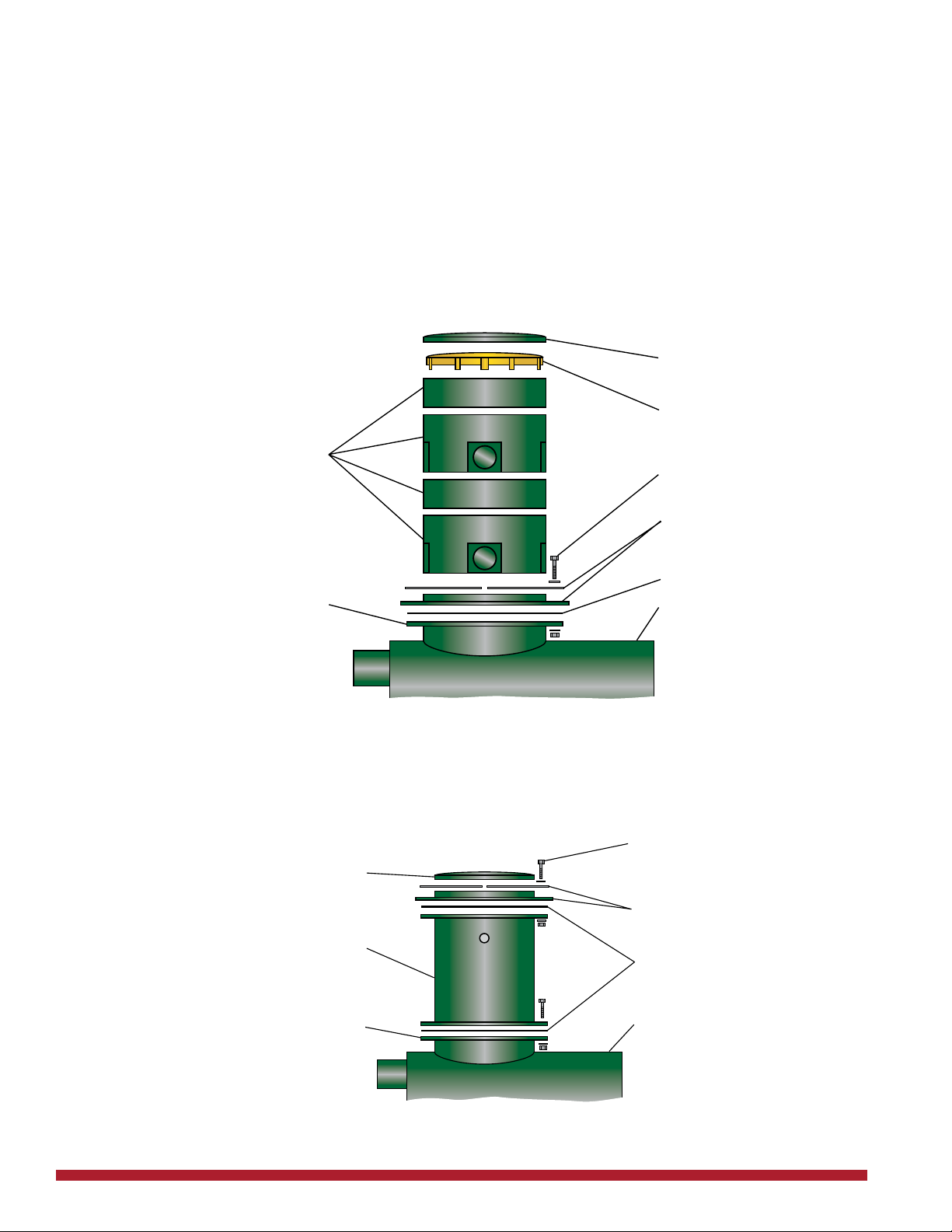
Manway Extensions PGI installations may include manway extensions to provide
access to the PGI from grade level. Highland Tank supplies two
types of extensions; a eld-adjustable, high-density polyethylene ris-
er or an exact-size, coated-steel one-piece manway riser. Both risers
bolt onto the PGI manway collars and employ gaskets to provide a
seal between components. Install risers based on the type supplied
with your PGI using diagrams below for guidance. See Fig. 9 and 10.
Nut, bolt &
washers
PGI
Manway extension
Steel Manway Extension
Gaskets
Manway collar on PGI
Manway adapter with
bolt-on retainer ring
Manway extension lid with
quick-release latches
PGI
Safety screen
Field-Adjustable Manway Extension
Manway extension lid with
quick-release latches
Two 12" sections with piping
access and two 6" sections
for custom fit on-site Nut, bolt and washers
Manway collar on PGI
Neoprene Gasket
Manway adapter with
bolt-on retainer ring
Fig. 10
Coated-Steel
Manway Extension
Fig. 9
Field-Adjustable
Manway Extension

www.highlandtank.com • 15
PGI is supplied with plain end connections for simple and easy
transition to inlet/outlet pipe system. Plain end connections must
be free of dirt and oils that may affect the proper and positive seal of
couplings to piping system.
Inlet piping installation should be straight and true with as few turns
as possible to limit turbulence. (When dielectric isolation is required,
consult Steel Tank Institute ACT-100-U® Installation Instructions,
R971 and Petroleum Equipment Institute PEI/RP100 for further in-
structions.)
Attach inlet/outlet piping (contractor supplied) to inlet/outlet
pipes on the PGI. Inlet and outlet inverts were established during
manufacturing. Do not modify without rst consulting Highland Tank.
The PGI inlet and outlet piping must be sloped from 1/8 inch to 1/4
inch per foot to maintain gravity ow. A greater slope, or a free fall
of wastewater in the PGI, will cause turbulence, adversely affecting
PGI performance. Piping must also be designed to limit ow into the
PGI to the ow rate specied. Use of a ow control device may be
necessary.
PGI outlet piping must be designed to ow at a rate equal to or
greater than the inlet piping to avoid any potential backup.
Attach manway extensions, riser and sensor pipes and any other
contractor supplied piping to the PGI. Take special care to prevent
damage to any gaskets or pipe threads.
Piping & Venting
Piping
16 • www.highlandtank.com
Piping & Venting
(continued):
Venting
PGI is designed for operation at atmospheric pressure ONLY.
Most codes require the outlet to be vented to atmosphere.
Conrm requirements with AHJ.
Vent piping requirements vary by code. Check with AHJ.
Terminate all vent piping per local code and AHJ.
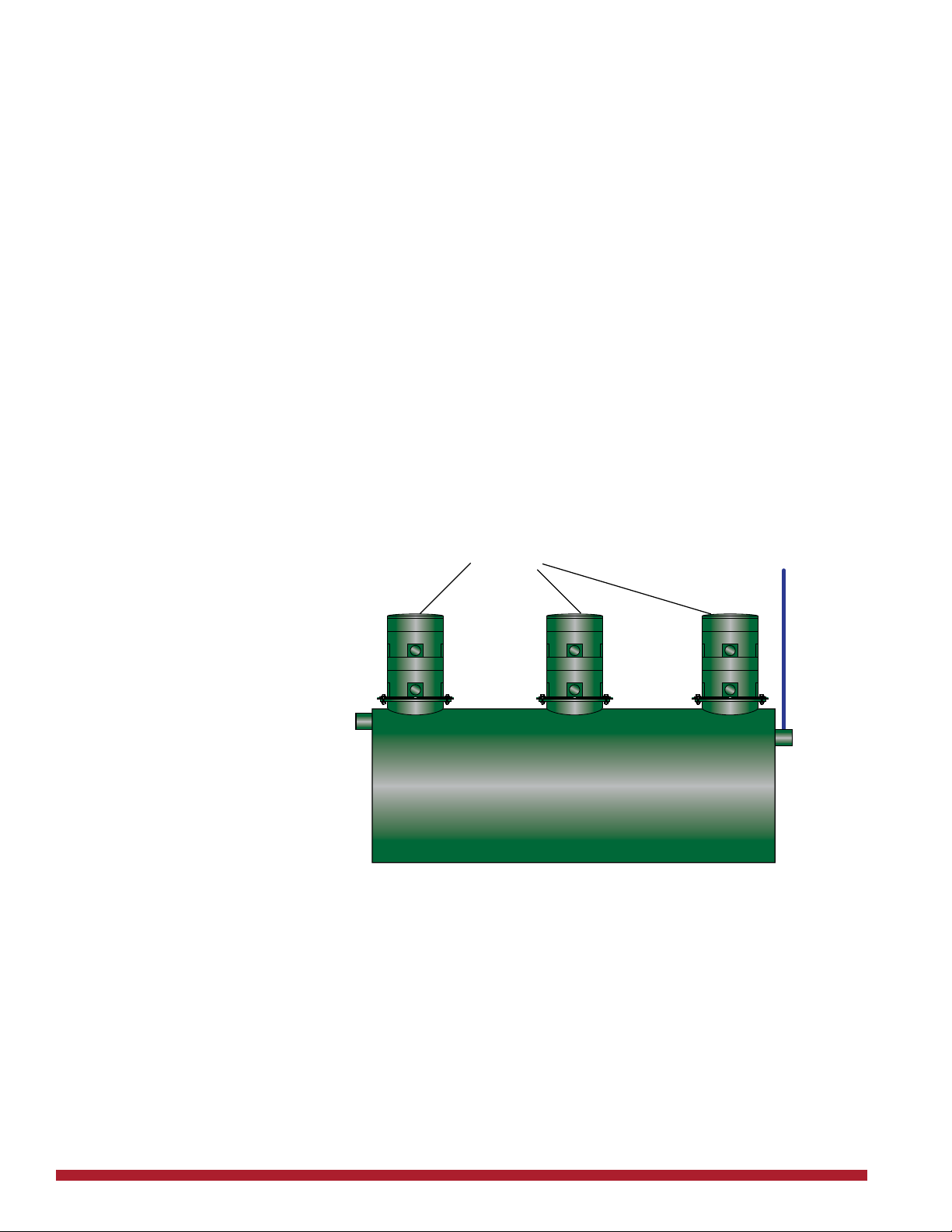
Consult AHJ for inlet and manway venting requirements. If required,
inlet and outlet must be vented to atmosphere separately. Manways
may be manifolded together. See Fig. 11.
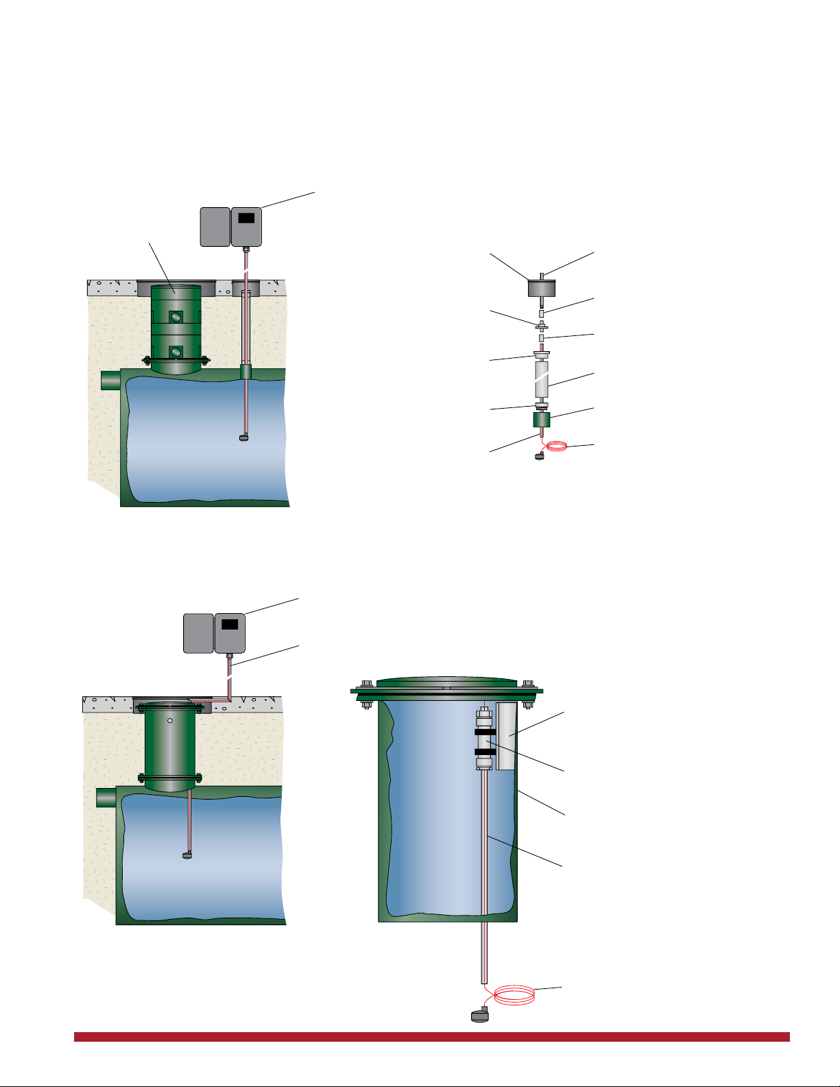
If PGI is equipped with a Highland Tank FOGSWatch probe, care
must be taken to provide proper access for periodic maintenance.
The FOGSWatch is installed either through an NPT tting or a man-
Fig. 11
Inlet
Outlet
Field Adjustable
Manways Risers
Passive Grease Interceptor
Outlet Vent Piping
by Installer
www.highlandtank.com • 17
way in the PGI. See Fig. 12 (NPT installation) or 13 (steel manway
riser installation) if applicable.
For PGIs with FOGSWatch sensor, pump-out pipes or other
piping, install riser pipes using compatible non-hardening sealant,
taking care not to cross thread or damage the nonmetallic bushings.
FOGSWatch Probe
Installation
Fig. 12
3/4" PVC coupling (glue - NPT)
3/4" Cord grip connector or
conduit to control panel*
Grade-level manway
if required
6" PVC plug fitted
with 3/4" PVC pipe stub
3/4" PVC coupling (glue - glue)
6" SCH 40 PVC as needed
to grade*
6" PVC
female adapter
6" PVC
male adapter 6" NPT fitting in PGI
FOGSWatch Transducer with
100' of cable. Thread cable
through PVC pipe and
connect to control unit.
3/4" PVC pipe
supplied at
proper length
Clean and seal all connections per local code during installation.
*Installer provided equipment.
FOGSWatch remote control unit & enclosure
}
Field Adjustable
Poly Manway
Riser
Fig. 13
Mounting bracket welded
to manway riser
PVC pipe guide
installed at factory
Clean and seal all connections per
local code during installation.
FOGSWatch remote control unit & enclosure
}
Installer provided conduit and wiring from
manway to control unit
FOGSWatch Transducer with
100' of cable. Ships loose.
Thread cable through PVC pipe
and connect to control unit.
Installed provided 3/4" PVC
pipe cut to length on site
Steel manway riser

18 • www.highlandtank.com
Sealing of Lifting Lugs
and Pipe Connections
Torque of 400 to 1,000 foot-pounds may be required to fully insert
pipe. Contact Highland Tank for specic wiring instructions.
During the installation process, steel can become exposed at the
lifting lug due to the handling of the PGI. These areas, along with all
other exposed steel surfaces, must be
covered using the coating kit supplied by the manufacturer.
Apply supplied coating touch-up to all exposed steel
surfaces of the PGI and allow to cure completely. Cure time will vary
depending on temperature and conditions.
After an air test has established tightness, apply coating to the PGI
ttings and allow to cure prior to backll. Coating must include the
entire plug on unused ttings.
After all coating touch-up applications, the installer must verify that
all of the coating has cured (adequate material hardness and solidi-
cation) prior to nal backll that will completely cover the PGI.
Deposit homogeneous backll carefully around PGI to a depth of at
least one foot over PGI to avoid damage to coating especially where
tamping is required. Refer to the National Fire Protection Associ-
ation’s Regulation NFPA 30 and state or local codes for minimum
depth of cover required.

www.highlandtank.com • 19
Finally, carefully deposit backll over the PGI up to the
elevation needed to complete grade level nishing. See Fig. 14 for
minimum burial depth. Consult approval drawing for maximum burial
depth.
Use grade level covers and street boxes to access the
manways, sensors, or pump-out pipes. The grade level
covers above the access manways must be of a greater
diameter (i.e. 36 inch grade level cover over a 24 inch access man-
way).
The PGI must be full of water to operate.
Separated FOG and vapors may be ammable
and/or combustible.
Depth of Cover in Areas Subject to Traffic
36"
6" Asphalt
30"
Unpaved
18"
Depth of Cover in Areas Not Subject to Traffic
8" Reinforced
Concrete
12"
6" Asphalt
12"
Unpaved
24"
4" Reinforced
Concrete
A
s
ph
a
l
t
8
8
"
R
ei
nf
or
d
d
Reinfor
C
oncret
e
6
"
A
s
p
h
R
e
in
fo
r
ced
ncrete
r
ce
d
d
rced
4
"
Co
Top of PGI
Fig. 14
Final Backlling

20 • www.highlandtank.com
PGI Start-Up
IMPORTANT:
CAUTION:
Filling the PGI
Service personnel must comply with all established OSHA
regulations governing the facility and services. These
include, but are not limited to, the use of approved breathing
equipment, protective clothing, safety equipment, etc.
When applicable, the nal state of all wiring must comply with
all electrical and re code standards.
This system must be properly vented by installer in
accordance with applicable plumbing and safety codes for vent-
ing of combustible gases.
When applicable, all electrical equipment, connections and
wiring must be protected from submergence and inltration of
water.
Open the PGI inlet and outlet pipe valves.
If the PGI has not yet been lled with water, as may have been re-
quired for balasting, (see page 13) ll with clean, fresh water at this
time. The PGI must be full of water before any wastewater can be
treated. The PGI can be lled through the facility’s drain leading to
the PGI inlet or through a manway.
If lling by manway, remove the manway lid and place the hose
through manway so that hose outlet rests inside the PGI.
The PGI is full when water drains out of the Outlet. Check the water
level using a gauge stick. The level on the gauge stick must equal
the invert of the Outlet Pipe as measured from the PGI bottom.
To ensure that no blockage exists, allow water to ow through the
facility drain which leads to the PGI Inlet. Check the Outlet Pipe to
make sure that water is owing through the PGI. Check the Inlet
Pipe and facility’s drain for water backup.
The efciency of the PGI can be maintained by following the
proper cleaning schedule and adhering to basic Best Management
Practices (BMP). See Appendix A.
Highland Tank manufactures a wide variety of models and designs-
for underground, underground vaulted and aboveground installation.
PGIs may be customized with options and accessories to meet spe-
cic site needs. Contact Highland Tank should you have any ques-
tions about a particular design or option.
This manual suits for next models
1
Table of contents
Other Highland Tank Industrial Equipment manuals

Popular Industrial Equipment manuals by other brands

ABB
ABB HT562470 Operation manual

Filtration Group
Filtration Group Air System Products Robo-Drain RD11-T Installation & operation manual

Avlite
Avlite AV-OL-75 Installation & service manual

M-system
M-system M8DY1 instruction manual

Mitsubishi Electric
Mitsubishi Electric M800VW Series Connection and set up manual

Siemens
Siemens AS-Interface operating instructions


