PushCorp SBS81 Series User manual

SBS81
Series
May, 2013
PUSHCORP, INC.
Dallas,

DO NOT USE LUBRICATED AIR.
This device requires a dry, non lubricated
100 psi (6.9 bar) maximum air supply
filtered to 5 µm and a 0.3 micron oil mist
separator.
Non compliance with these requirements
will void the manufacturer’s warranty.
(See Section 3.4)
All fasteners, mounting holes and pipe
threads on this tool are METRIC.
NEVER OPERATE THE
SBS81 MANUALLY
NEVER OPERATE THE SBS81 WITH
PERSONEL IN THE WORKCELL
All PushCorp, Inc. electrical cables are rated for
high twist and flex robotic applications with a
minimum cable bending radius specification of
125mm (5 in). Cable damage resulting from
failure to abide by this specification will not be
covered under warranty.

PUSHCORP, INC.
SBS81 Series Manual 1
Table of Contents
1.0 LIMITED WARRANTY.............................................................................................2
2.0 GENERAL OVERVIEW...........................................................................................4
3.0 INSTALLATION.......................................................................................................5
3.1 Mounting the SBS81.......................................................................................................................... 5
3.2 Electrical Connections....................................................................................................................... 5
3.3 Electrical Control Box........................................................................................................................ 8
3.4 Pneu atic Connections..................................................................................................................... 8
4.0 OPERATION............................................................................................................10
4.1 Belt Media Installation and Re oval..................................................................................................10
4.2 Belt Media Tracking........................................................................................................................... 11
4.3 Achieving Desired Force.................................................................................................................... 11
4.4 Achieving Desired Belt Media Speed................................................................................................. 11
4.5 Servo Motor Drive Belt Replace ent................................................................................................. 12
4.6 Contact Wheel Replace ent............................................................................................................. 12
4.7 Contact Wheel Position Feedback..................................................................................................... 12
5.0 TECHNICAL SPECIFICATIONS.............................................................................13
Copyright PushCorp, Inc. 2019. All rights reserved

PUSHCORP, INC.
SBS81 Series Manual 2
1.0 Limited Warranty
Duration:
One year fro date of delivery to the original purchaser.
Who gives this warranty (warrantor):
PushCorp, Inc.
Telephone: (972) 840-0208
Corporate Address:
P. O. Box 181915
Dallas, Texas 75218
Shipping Address:
3001 W. Kingsley Rd.
Garland, Texas 75041
Who receives this warranty (purchaser):
The original purchaser (other than for purposes of resale) of the PushCorp, Inc.
product
What products are covered by this warranty:
Any PushCorp, Inc. Adjustable Force Device or Adjustable Force Device
accessory supplied or anufactured by the Warrantor.
What is covered under this warranty:
Defects in aterial and/or work anship which occur within the duration of the
warranty period.
What is NOT covered in this warranty:
A. IMPLIED WARRANTIES, INCLUDING THOSE OF MERCHANT-ABILITY
AND FITNESS FOR A PARTICULAR PURPOSE ARE LIMITED TO ONE
YEAR FROM THE DATE OF ORIGINAL PURCHASE. So e states do not
allow li itations on how long an i plied warranty lasts, so the above
li itations ay not apply to you.
B. ANY INCIDENTAL, INDIRECT, OR CONSEQUENTIAL LOSS, DAMAGE or
EXPENSE THAT MAY RESULT FROM ANY DEFECT, FAILURE,
MALFUNCTION OF THE PUSHCORP, INC. PRODUCT. So e states do not
allow the exclusion or li itation of incidental or consequential da ages so
the above li itation or exclusion ay not apply to you.
C. Any failure that results fro an accident, purchaser's abuse, neglect,
unauthorized repair or failure to operate the products in accordance with the
instructions provided in the owner's anual(s) supplied with the product.
Responsibilities of the Warrantor under this warranty:
Repair or replace, at Warrantor's option, products or co ponents which have
failed within the duration of the warranty period.
Copyright PushCorp, Inc. 2019. All rights reserved

PUSHCORP, INC.
SBS81 Series Manual 3
Responsibilities of the purchaser under this warranty:
A. Deliver or ship the PushCorp, Inc. product or co ponent to PushCorp, Inc.
Service Center, Dallas, TX. Freight and insurance costs, if any, ust be
borne by the purchaser.
B. Use reasonable care in the operation and aintenance of the product as
described in the owner's anual(s).
When warrantor will perform repair or replacement under this warranty:
Repair or replace ent will be scheduled and serviced according to the nor al
work flow at the service center, and depending on the availability of replace ent
parts. Purchasers requiring quicker repair ay receive such with pay ent of a
PushCorp, Inc. predeter ined expediting fee.
This Li ited Warranty gives you specific legal rights and you ay also have other rights
which vary fro state to state.
Copyright PushCorp, Inc. 2019. All rights reserved

PUSHCORP, INC.
SBS81 Series Manual 4
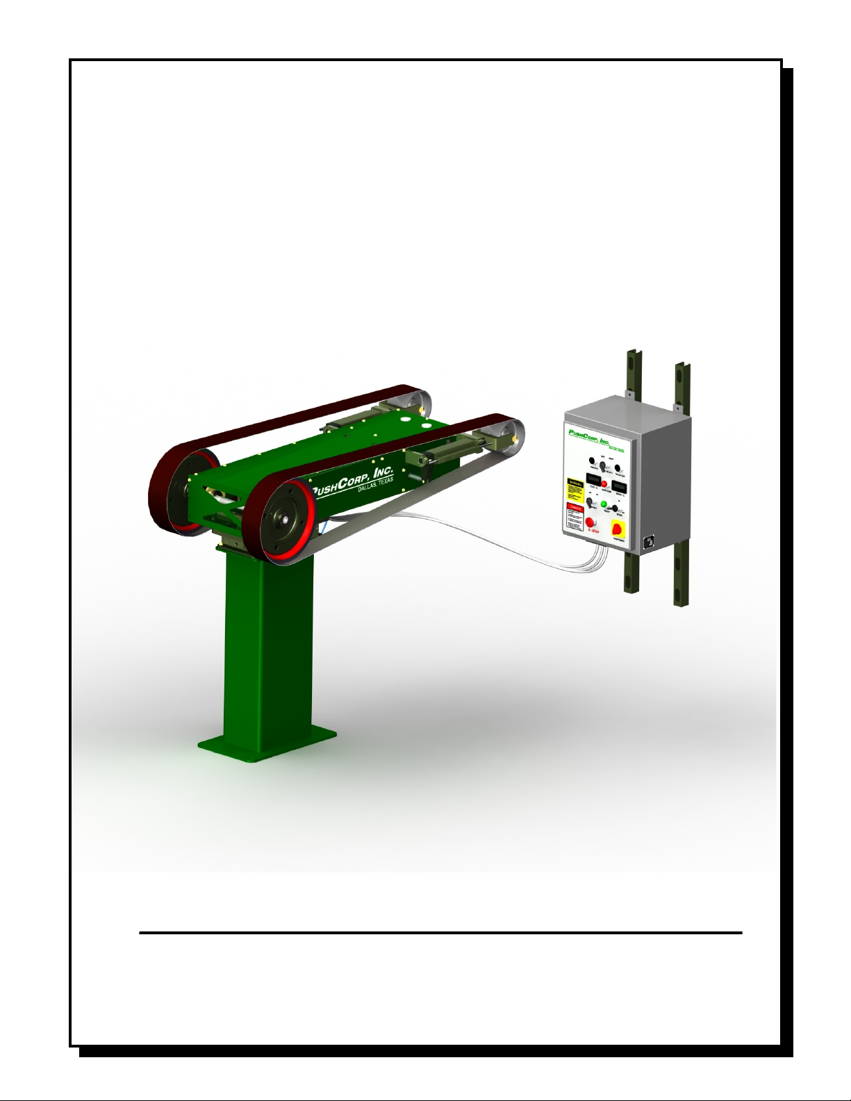
2.0 General Overview
The PushCorp SBS81 Series Servo Belt Stand co bines passive co pliant force
control and closed-loop servo otor speed control technology. The SBS81 has been
designed fro the ground up as a belt stand for robotic finishing with any new and
unique features. Accurate force and speed control allows you to achieve unprecedented
levels of quality and consistency. The SBS81 enables axi u flexibility for any part-
in-hand grinding, sanding, buffing or polishing application. Linear co pliance with 1.6
inches (40 ) of travel and excellent access allow a robot to easily anipulate parts
over the Belt Media. An i portant feature of the SBS81 Belt Stand is the high torque
servo otor and belt drive. The belt drive syste provides a 2:1 increase in torque at
the contact wheels for heavy aterial re oval.
The force control technology in the SBS81 is based on the PushCorp Passive AFD80
Series Force Devices. This technology has proven itself in thousands of hours of
production robotic applications. A basic regulator supplied with SBS81 allows the
SBS81’s force to be varied fro 0 to 50 lbs. (0 to 222 N). This regulator has a coarse
adjust ent and ust be anually set to the desired force output. If the force ust vary
during the finishing process, then an electrically controlled proportional regulator is
required. Very accurate force output requires a precision regulator that operates in a
narrow pressure range.
The SBS81 has a nu ber of notable features that contributes to ease-of-use, and
greater throughput. The Belt Media can be tracked re otely outside the work cell for
convenience and user safety. When the Belt Media needs replacing the operator
anually releases the tension using a lever ounted right on the unit. A belt tension
sensor is provided to notify the user that the Belt Media has not been tensioned. A belt
break sensor is also provided to notify the user if the Belt Media should break. These
sensors can be used by the custo er to progra faults to prevent the syste fro
starting should the Belt Media not be tensioned, or to ove the robot away, and stop the
syste should a belt break. These features protect the user and equip ent, while also
reducing downti e.
In ost any finishing process, consistency is of para ount i portance. For this reason
the SBS81 is powered by a high torque servo otor with adjustable speed control that
can be varied at any ti e during the finishing process. The SBS81 has a 5.7
horsepower (4.28 kW) otor that supplies 14.7 lbft (20 N) of torque and a axi u
speed of 2000 RPM at the contact wheels. This provides a range of Belt Media surface
speeds up to 7330 SFPM (Surface Feet Per Minute). The SBS81 requires 14 inch (356
) dia eter Contact Wheels with a width of 2”, 3”, or 4”. The unit is setup to use
standard 132 inch long Belt Media. For ulti- edia finishing applications, the rubber
contact wheel can be replaced with Scotchbrite, or cloth wheels. This flexibility allows
the SBS81 to perfor a wide variety of finishing applications.
Copyright PushCorp, Inc. 2019. All rights reserved

PUSHCORP, INC.
SBS81 Series Manual 5
3.0 Installation
3.1 Mounting the SBS81
The SBS81 Servo Belt Stand is secured by four (4) fasteners passing through ounting
holes located in the Base Plate (See Figure 4). The Base Plate ounting hole locations
are shown in Figure 1. The SBS81 ust be securely ounted to keep the unit fro
oving during operation. The unit ust be ounted level to achieve the desired force
output at the Contact Wheels. A spirit level can be place on the top of the Belt Stand
and shi s can be inserted under the Base Plate as required.
WARNING: Do NOT operate the unit without first mounting it securely.
Figure 1. SBS81 Base Plate
The SBS81 attaches with four (4) fasteners, 1/2 inch (12 ) in dia eter. These
fasteners are to be provided by the installer.
3.2 Electrical Connections
The SBS81 requires 208 - 480 VAC 3-Phase 50-60 Hz. power to operate. This should
be supplied to the Power Connector on the Control Box. The electrical interface for
servo otor control, AFD feedback, and Belt Media tracking is operated through the
User Interface Connector. Figure 2 shows a typical anual interface sche atic, which
Copyright PushCorp, Inc. 2019. All rights reserved

PUSHCORP, INC.
SBS81 Series Manual 6
the custo er could i ple ent. The unit is supplied with plugs for both the Power
Connector and User Interface Connector
Figure 2. SBS81 Typical User Interface Sche atic
The circuit diagra in Figure 2 shows the SBS81 wired for stand-alone panel operation.
All circuitry on the SBS81 is designed for 24 VDC control voltages.
The switch ele ents connected to Pins 16, 17, and 18 control the re ote belt tracking
feature of the unit. The right and left side are defined by viewing the unit fro the front
facing the Contact Wheels. The selector switch connected to Pin 16, deter ines which
side will be controlled for the belt tracking operation. The push button switches on Pins
17 and 18 turn on the selected belt tracking actuator to track the belt outward and
inward respectively. These custo er panel ount push buttons ay be replaced with
relays if re ote robot teach pendent operation is desired.
The Belt Media/Contact Wheel speed is controlled via a 0 - 10 VDC analog signal
applied to Pins 9 and 10. Providing a positive analog voltage will rotate the Contact
Wheels in a downward direction when facing the unit fro the front. The SBS81 is
nor ally rotated in this direction to direct dust to the floor or into a user supplied dust
collection syste . The analog input is a true floating differential signal connected
directly to the servo a plifier. The circuit shown in Figure 2 is an exa ple of how the
Contact Wheel speed ay be controlled with a si ple panel ount linear potentio eter.
If re ote robot teach pendent adjust ent is desired, the potentio eter would be
Copyright PushCorp, Inc. 2019. All rights reserved

PUSHCORP, INC.
SBS81 Series Manual 7
replaced with a 0 - 10VDC analog signal fro a robot or PLC analog output card
connected directly to Pins 9 and 10.
WARNING: The differential voltage applied to Pins 9 and 10 should not exceed 10
VDC or damage will occur to the servo amplifier.
Ter inal 7, shown in Figure 2 provides the servo a plifier enable signal. Connecting
Ter inal 7 to +24VDC enables the servo a plifier and applies voltage to the servo
otor. Re oving voltage fro ter inal 7 disables the a plifier.
The “DRIVE OK” output on Ter inal 11 should be continuously onitored by the End-
user control syste . This signal should be “ON” during nor al operation. An “OFF”
condition indicates a drive fault. The cause of the fault will be indicated by a flashing
code on the servo drive a plifier.
OPERATION SHOULD CEASE UNTIL THE FAULT CONDITION IS CORRECTED.
The Electrical Control box includes a built-in E-Stop push button switch that, when
pressed, i ediately re oves all electrical power fro the otor. If desired, the SBS81
can be connected to an external, dual-channel, E-Stop circuit by connecting to the STO1
and STO2 signal on Ter inals 3, 4, 5, and 6 as shown.
It is the responsibility of the System Integrator or End user to follow all applicable
electrical codes and OSHA safety standards when wiring the SBS81. This
includes the proper and judicious use of fuses, contactors, cut off switches, lock
out switches, and Emergency Stop circuits. PushCorp, Inc. assumes no
responsibility or liability for the electrical system design and implementation of
the SBS81 in the End user application. Refer to OSHA rules and regulations, as
well as the CE Machinery (IEC 204 1), when designing systems that include
motors and drives to ensure that the user is protected.
PushCorp will provide answers to any questions regarding the servo drive syste and
will be responsible for any warranty issues.
Copyright PushCorp, Inc. 2019. All rights reserved

PUSHCORP, INC.
SBS81 Series Manual 8
3.3 Electrical Control Box
The SBS81 Electrical Control Box is designed to be wall ounted outside the robot work
area in a relatively clean environ ent. Figure 4 shows the ounting di ensions of the
electrical enclosure.
Figure 3. Electrical Control Box Mounting
It is the responsibility of the installer to punch holes in the enclosure for conduit and/or
cord grips as required for the electrical supply power wiring and low-voltage control
signals.
3.4 Pneumatic Connections
The SBS81 Belt Stand requires a dry, non-lubricated, 5 icron filtered, 80 to 100 psi (5
to 7 Bar) air supply with a 0.3 icron oil ist separator. Failure to provide supply air to
these specifications can degrade perfor ance and will void any warranty repairs
concerning pneu atic co ponents. Additionally, a minimum 80 psi (5 Bar) air pressure
ust be aintained for the device to operate within published specifications. Low air
pressure will cause inferior force control perfor ance and not allow the Belt Media to be
properly tensioned.
The pneu atic supply syste should be configured as shown in Figure 3.
Copyright PushCorp, Inc. 2019. All rights reserved

PUSHCORP, INC.
SBS81 Series Manual 9
Figure 4. Pneu atic configuration
WARNING: If water condensation is a problem in your air supply system, an air
dryer device is highly recommended. Moisture inside the device will cause
premature failure that will not be covered under warranty.
The SBS81 Belt Stand aintains a positive air pressure to i pede the infiltration of
conta inate aterials. It is i portant to provide a continuous co pressed air supply to
the device at all ti es if the work environ ent contains airborne conta inates. If the
environ ent is clean during non-operational periods, the air supply to the device ay be
shut off.
The SBS81 has one pneu atic input, an R 1/8 (Metric) port located on the SBS81
Control Box (Figure 3). This port supplies all the air needed to operated the Belt Stand.
Before connecting the supply to the air fitting, open the supply valve to blow out any
conta inates which ay be in the line. Charge the supply line with co pressed air and
verify that there are no air leaks and that there is a ini u of 80 psi (5 Bar). If a
ini u air pressure of 80 PSI cannot be achieved, then an auxiliary air co pressor or
booster pu p ust be installed.
Copyright PushCorp, Inc. 2019. All rights reserved

PUSHCORP, INC.
SBS81 Series Manual 10
4.0 Operation
4.1 Belt Media Installation and Removal
The SBS81 uses 2”, 3”, or 4” wide by 132” long Belt Media. To install new Belt Media,
verify the servo otor and robot are disabled, then position the Belt Media Tension
Release Lever towards the Contact Wheels of the SBS81, which releases the tension on
the Belt Media. Install new Belt Media over the Contact Wheel and the Tracking Wheel
as shown in Figure 4. Then tension the Belt Media by positioning the Belt Tension
Release Lever to its rearward position. To re ove the Belt Media reverse the previous
steps.
Proper tension is required for each Belt Media width and type. The Belt Tension
Pressure Adjust ent Knobs are located at the rear of the achine, see Figure 4. The
Belt Media tension should never be adjusted while the achine is operating. Belt Media
Tension Pressure Gauges are located on the top of the achine to allow accurate
setting of the pressure. The following chart is only a guideline for proper Belt Media
tension pressures. The user is responsible for contacting the Belt Media anufacturer
for the correct Belt Media tension.
Belt Width Belt Media Tension Pressure Belt Media Tension
2” 0.4 MPa 57 lbs. (254 N)
3” 0.5 MPa 71 lbs. (316 N)
4” 0.6 MPa 85 lbs. (380 N)
.1 MPa Belt Media Pressure Gauge = 14.2 lbs. (63.1 N) Belt Media Tension
Copyright PushCorp, Inc. 2019. All rights reserved

PUSHCORP, INC.
SBS81 Series Manual 11
4.2 Belt Media Tracking
The SBS81 uses electro echanical linear actuators to auto atically adjust and hold the
tracking of the Belt Media on the Contact Wheels. The Belt Media cannot be tracked
anually. The user oves the Tracking Wheel by auto atically extending or retracting
the Linear Actuator. Moving the Linear Actuator will cause the Belt Media to track fro
side to side on the Contact Wheel. The Belt Media can only be tracked while the
Contact Wheels are rotating. The Contact Wheels should be rotated at approxi ately
500 rp . Atte pting to track the Belt Media at high rp ’s will cause the belt to ove too
quickly. The user ust select which Tracking Wheel is to be adjusted. The Linear
Actuators cannot be back-driven and will hold their position.
4.3 Achieving Desired Force
The SBS81 uses a passive 80 Series AFD to supply a co pliant force fro 2 to 100 lbs.
(8 to 445 N). The passive force device requires the user to provide regulated air
pressure to achieve a desired force output at the Contact Wheels. Use the following
equations to deter ine the pressure required to achieve the desired output force:
units Metric )89(
unitsEnglish )4.1(
sam
sa
PF
PF
Where:
bar)or (psi pressureSupply
eelsContact What (N) force applieNet
eelsContact What (lbs.) force applieNet
s
am
a
P
F
F
PushCorp has included a anual regulator in the SBS81 Control Box to allow for quick
set-up. A anually adjustable pressure regulator ay be sufficient, but if re ote
operation of the force output is needed, then an electrically controlled proportional air
regulator will be required. The accuracy of the force output is directly related to the
precision and quality of the pressure regulator. For the ost precise force output a
regulator that operates in a li ited range (i.e., 0-15 psi) is required.
4.4 Achieving Desired Belt Media Speed
The Belt Media speed and Output Shaft rp is controlled via a +/- 10 VDC analog signal
applied to Pins 4 and 5 of the User Interface Connector. The user ust scale the
co and voltage to the servo otor a plifier fro 0 to 10 Volts, which equates to a
Belt Media speed of 0 to 7330 SFPM (Surface Feet Per Minute). The user is
responsible for deter ining the axi u speed for their Belt Media. The SBS81 is
factory li ited to operate at a axi u Output Shaft rotational speed of 2000 rp
(7330 SFPM Belt Media speed). Figure 2 shows a si ple circuit using a linear
potentio eter to control Belt Media speed, however ost installations will require a
re ote voltage co and to vary the Belt Media speed and control the
acceleration/deceleration of the unit.
Copyright PushCorp, Inc. 2019. All rights reserved

PUSHCORP, INC.
SBS81 Series Manual 12
4.5 Servo Motor Drive Belt Replacement
The SBS81 uses a 2:1 reduction ti ing belt drive to transfer power fro the Servo Motor
to the Contact Wheels. This drive incorporates a high-strength Gates Poly Chain GT2
belt, PushCorp Part No. PAR01889-1. Should this Drive Belt ever require replace ent,
contact PushCorp for the proper procedure.
4.6 Contact Wheel Replacement
Contact Wheels are not provided with the SBS81, as the user ust deter ine the proper
style and hardness for their specific application. The 14” dia eter Contact Wheels are
easily installed or replaced on the SBS81. They are available in different widths (2”, 3”,
or 4”), duro eters (hardness), and surface types (plain or serrated). Using different
width Contact Wheels on the SBS81 does not require any odifications to the unit.
Contact Wheels should be ordered directly fro the anufacturer, Contact Rubber
Corp., 8635 198th Avenue, Bristol, WI, 53104, Tel: 262-857-2361, Fax: 262-857-9483.
The SBS81 uses C-134 type Contact Wheels. There are four (4) M10x1.5 Flat Head
Socket Screws on the Contact Wheel hub that ust be re oved to change the Contact
Wheel. After re oving the screws the hub will split allowing the Contact Wheel to be
easily re oved. Install a Contact Wheel on the hub and replace the re oved hub and
the four (4) screws. Tighten the screws to 30 ft.-lbs. (40 N· ).
4.7 Contact Wheel Position Feedback
The SBS81 co es equipped with an internal potentio eter that provides a 0-10 volt
signal based on the linear position of the Contact Wheels. The voltage signal is at a
ini u value when the Contact Wheels are pushed back against the rubber stops,
and a axi u value when the Contact Wheels are pulled forward against the rubber
stops. The total linear co pliant stroke is 1.6 in. (40 ).
The linear position signal ust be calibrated for each installation. User calibration is
easily acco plished using the following steps.
1. Turn off the supply air to the SBS81
2. Move the Contact Wheels to the full rearward (negative) position.
3. Read the voltage signal on Pin 13 of the User Interface Connector. Record
this voltage for future reference. This will be referred to as Vneg.
4. Move the Contact Wheels to the full forward (positive) position.
5. Read the voltage signal on Pin 13 of the User Interface Connector. Record
this voltage for future reference. This will be referred to as Vpos.
Copyright PushCorp, Inc. 2019. All rights reserved

PUSHCORP, INC.
SBS81 Series Manual 13
6. The position of the Contact Wheels can now be deter ined by easuring the
current voltage (V ) on Pin 13 of the User Interface Connector, and inserting
the value into the following equation:
unitsMetric
VV
VVm
mmp
unitsEnglish
VV
VVm
inp
negpos
neg
negpos
neg
40
.6.1
Where,
mm)inch(sition (V)arriage popositive C at fully ed voltage= CalibratV
mm)inch(tion (V)riage posigative Cart fully ne voltage aCalibratedV
(V)PI 12asured on Voltage meVm
mm)in.Position (Wheel Contactp
pos
neg
40,6.1,
0,0,
,
5.0 Technical Specifications
Maxi u Applied Force: 50 lbs. (445N)
Contact Wheels: 2”-4” Widths, 14” Dia
Abrasive Belt Media: 2”-4” Widths, 132” Length
Weight: 450 lbs. (204 kg)
Force Scale Factor: 1.4 lbs/psi (890 N/MPa)
Co pliant Stroke: 1.6 in. (40 )
Supply air: Non-lubricated, Dry, 5µ Filtered, 100 psi (0.7 MPa) Max.
Supply Voltage: 240 VAC, 3-Phase
Max. Cont. Current: 30 A ps
Max. Peak Current: 60 A ps (2 Seconds)
Specifications subject to change ithout notice.
Fastener Tightening Torque Specs
Torque Mini u Depth
Fastener Size in.-lbs. ft.-lbs. N· in.
M4 x .7 50 4.2 5.6 0.17 4.3
M5 x .8 85 7.1 9.6 0.21 5.3
M6 x 1 140 11.7 15.8 0.25 6.3
M8 x 1.25 348 29.0 39.3 0.33 8.4
M10 x 1.5 600 50.0 67.8 0.41 10.5
Copyright PushCorp, Inc. 2019. All rights reserved
Table of contents
Other PushCorp Industrial Equipment manuals

PushCorp
PushCorp AFD310 User manual

PushCorp
PushCorp AFD1240 User manual

PushCorp
PushCorp SWS100-3.7 User manual

PushCorp
PushCorp 620 Series User manual

PushCorp
PushCorp AFD92 User manual

PushCorp
PushCorp RPC100-75 User manual

PushCorp
PushCorp AFD1200 User manual

PushCorp
PushCorp AFD1000 Series User manual
Popular Industrial Equipment manuals by other brands

Agilent Technologies
Agilent Technologies RMSH–2 Installation sheet

GSi
GSi 2000 Series Operator's manual

HEIDENHAIN
HEIDENHAIN KGM 101 Mounting instructions

Klimawent
Klimawent SCT-2100 Use and maintenance manual

ABB
ABB TPL65-A10 Operation manual

Schmid & Wezel
Schmid & Wezel EFA cutter Z079 Translation of the original operating instructions