Filtration Group Air System Products Robo-Drain RD11-T User manual

Robo-Drain
Zero-Loss Condensate Drain
Model RD11-T
AIR SYSTEM PRODUCTS
51 Beach Ave.
Lancaster, NY 14086
716/683.0435
ASPSalesT[email protected]
www.airsyspro.com
Installation & Operation Manual
Making the World Safer, Healthier & More Productive

TABLE OF CONTENTS
GENERAL INFORMATION ............................................................................................................................ 3
SAFETY ....................................................................................................................................................... 3
WARRANTY .............................................................................................................................................. 3
INSTALLATION ....................................................................................................................................... 4
PRODUCT INFORMATION
INSTALLATION ................................................................................................................................. 4
POST-INSTALLATION CHECK ......................................................................................................... 4
TROUBLESHOOTING ....................................................................................................................... 4
OPTIONS ........................................................................................................................................... 4
INSTALLATION CONSIDERATIONS ................................................................................................... 5
RECEIVER ....................................................................................................................................... 5
FILTER AND AFTERCOOLER SEPARATOR ................................................................................. 5
REFRIGERATED DRYER ............................................................................................................... 5
INTERCOOLERS ............................................................................................................................. 5
BALANCE LINE ............................................................................................................................... 5
GENERAL SPECIFICATIONS ............................................................................................................. 6
DIMENSIONAL DRAWING .................................................................................................................. 7
EXPLODED PARTS DRAWING .......................................................................................................... 8
PARTS LIST ......................................................................................................................................... 9
MAINTENANCE ................................................................................................................................... 9

3
GENERAL INFORMATION
SAFETY
Locate, read, understand and follow all Danger, Warning, Caution, and Operating Instructions on the product
and in all Manuals. Failure to comply with safety precautions described in the manuals supplied with the product
this manual or any of the labels and tags attached to the product may result in death, serious injury or property
damage.
Check that all labels, tags and data (name) plates are in place and legible. It is your responsibility to ensure this
information available to others.
If you have any questions about safety or procedures not included in this manual, ask your distributor or contact
Air System Products, LLC.
GENERAL DESCRIPTION
For the condensate to properly enter the Robo-Drain reservoir, the condensate line to the Robo-Drain must
always be installed below the source to be drained. It is equally important to provide a means, such as a balance
line, for the air in the reservoir to be displaced as condensate enters the drain. If the air cannot be displaced, the
condensate will not enter the reservoir. Please review the following suggestions that might best fit your
installation. The use of unions and shut-off valves are recommended for both the condensate line and the balance
line.
WARRANTY
The Robo-Drain is warranted to be free from defects in workmanship and materials for a period of two years from
the date of shipment. The liability of the manufacturer is limited to repair or replacement of the drain at its option.
In no event shall the manufacturer be liable for special or consequential damages or for delay in performances
of this warranty.

4
The Robo-Drain is designed for trouble-free operation.
When installed and operated properly, the Robo-Drain will
provide years of reliable service collecting and discharging
condensate, along with pipe scale and other contaminants
typically found in a compressed air system.
INSTALLATION
Before installing the drain, ensure the source vessel is
isolated from the interconnecting piping to the drain.
Confirm the air system pressure will not exceed the 250 PSI
(17 bar) rating of the drain and the inlet temperature should
not exceed 180 oF (82 oC).
Connecting drain should be done by using one of the
recommended installation diagrams shown on following
page. The installation of a pre-strainer is not required or
recommended.
Install the drain on a level surface and as close to the source
to be drained as possible. Since the Robo-Drain uses gravity
to fill the reservoir, the entire drain must be installed below
the source when using the top inlet. It isn’t recommended
that flexible tubing be used on the discharge to prevent it
from whipping casing damage or injury.
If the drain is to be installed where the temperatures can fall
below 32oF (0 oC), special precautions are needed, including
but not limited to heat tracing pipelines and the optional
immersion heater.
The Robo-Drain will accept condensate from either the
upper or the lower inlet connections. The upper inlet
connection is preferred. The inlet port not used must be
plugged by using a standard plug.
A balance line is highly recommended to avoid an air-lock
condition. The balance line should be connected to the
source device to prevent a flow path for system air or
condensate.
The drain has a 1/8” NPT vent connection to permit easy
installation of a balance line. Use a non-galling pipe sealant
on all joints.
The use of isolation valves and bypass piping will permit
quick and easy routine maintenance.
The Robo-Drain uses compressed air to drive (control) a
drain cycle. ONLY CLEAN DRY AIR MUST BE USED! The
required control air pressure for the standard models,
irrespective of system pressure is 60-130 PSIG (4.1-9.0
barg) Any of the Robo-Drain models can be supplied as an
LP variant and will model should be between 40 and 130
PSIG (2.8 and 9.0 barg).The Robo-Drain is supplied with a
filter for installation on the control head. The use of unfiltered
air can result in failure and can void the product warranty.
Once installed and control air supplied, the drain is ready to
be placed in service.
CHECKING THE OPERATION
After installation is complete and the drain is in service, a
check should be made that the drain is functioning properly.
1. Ensure that condensate is properly entering the
reservoir. This can be easily done looking through the
translucent reservoir
2. Press the test button to ensure the drain valve opens and
closes when the button is released.
3. Inspect for any air or condensate leaks. Correct as
necessary.
TROUBLESHOOTING
If condensation is not entering the reservoir, check for the
following:
1.
Check that any valves between the source and drain are
open.
2.
Check that the balance line is open and properly
installed. Alternatively, that the vent valve is cracked
open.
If the drain is not emptying:
1. Press the test button to force a manual drain cycle. If the
air actuator does not open the valve , check that the
control air supply is at least the minimum pressure
required.
2. If the valve opens, but the drain does not empty quickly,
no more than 20 seconds, ensure that there is system
pressure.
3. If still not emptying, check the downstream piping from
the drain valve to ensure there isn’t a closed valve or an
obstruction.
4. If the drain is still not draining, suggest contacting the
factory.
OPTIONS
High Level Alarm
Mechanical Cycle Counter
Digital Cycle Counter

5
INSTALLATION CONSIDERATIONS
For the condensate to properly enter the drain reservoir, the
condensate line to the drain must always be installed below the
bottom of the vessel to be drained. It is equally important to provide
a means for the air that is contained in the reservoir to escape (vent)
as the condensate enters the reservoir. If the air cannot escape, the
condensate will not enter the reservoir. Below are suggestions on
how to best install the drain on typical types of vessels that have to
drained of condensate. However, it is possible to install the drain
without a balance line (Dwg. not shown), providing the condensate
enters the top inlet and the flow rates are less than 9 GPH (750
SCFM for an aftercooler or 1,500 SCFM dryer) for a 1/2" drain line
and 19 GPH (1,500 cfm for an aftercooler or 3,000 SCFM dryer) for
a 3/4" line. The use of unions and shut-off valves are recommended
for both the condensate line and the balance line.
RECEIVER TANK
The preferred installation for this drain on a receiver tank is having
the condensate enter the top inlet port and having the balance line
go back to the tank at a position that is above the level of the
condensate. (See Dwg. 1).
FILTER and AFTERCOOLER MOISTURE SEPARATOR
If a cyclone separator or filter has pipe plugs located in the top of
the head, the plug closest to the discharge pipe should be removed
and the balance line should be installed (Dwg. 2). If there is no
provision on the cyclone separator or filter for a balance line, install
it in the discharge side of the pipeline and as close to the cyclone
separator as possible.
REFRIGERATED DRYER
If a balance line is required, it must be connected to the port located
on top of the separator that is closest to the discharge side (Dwg.
2), or between the separator and the air-to-air heat exchanger. If a
port is not available as described above, then venting to
atmosphere is recommended. When venting to atmosphere, the
condensate should enter through the bottom entry port on the drain.
The bleed or needle valve is installed on the 1/8" NPT vent port and
allows the air in the drain reservoir to escape to the atmosphere
(Dwg 3). The bleed valve (not included) should be adjusted so that
only 3 to 5 bubbles per second are visible. It is not recommended
to install a vent line downstream from the dryer. The vent line can
be a conduit for transferring moisture from the drain to the
previously dried air. This can result in unwanted moisture being sent
down stream.
INTERCOOLERS
Install the condensate drain line into the upper port only. This will
prevent the possibility of condensate being drawn back into the
intercooler on some systems. It is important that the vent line be
installed on the same stage that is being drained or to atmosphere.
BALANCE LINE
As mentioned above, both the use and the placement of a balance
line is very important. Most drain failures are the result of an
improper balance line installation. The balance line should be 1/4"
tubing or larger, and installed on top of a pipe or vessel, not the
bottom. A needle valve is recommended for controlling the air flow.
Avoid having any loops or low areas in the balance line that might
allow moisture to collect in the line and prevent the passage of air
from the drain’s reservoir.
DWG 1.
DWG 3.
DWG 2.

6
GENERAL SPECIFICATIONS
Inlets: Two (2) 3/4" NPT (BSPP Optional)
Outlet: 1/2" NPT (BSPP Optional)
Power: Clean, Dry Air: 60 - 130 PSI (Standard Design)
40 – 130 PSI (Low Control Pressure Design Option)
Operating Pressure: 0 to 250 PSI
Vacuum and High Pressure Designs Available
Operating Temperature: 32° to 180° F.
Optional Immersion Heater Available
Weight: 17 lbs. (Shipping)
26 lbs. Filled & Installed
Discharge: 24 ounces per cycle
Capacity: 6,600 SCFM at aftercooler*
*Capacity may be more or less depending on application
MATERIALS
Reservoir: Aluminum and Composite
Stainless Steel and Nickel-plated Optional
Drain Valve: Bronze w/SS Ball and Stem (Full SS Optional)
Trigger Float: Stainless Steel
Trigger Seat: Stainless Steel
Trigger Seal: Viton®
Control Tubing: Nylon 66
Stainless Steel Tubing and Fittings Optional
MODEL CONFIGURATION
RD11 -
LP T -
A
-
H
-
SSV
SSE
SS
NPT
BSPP
EXAMPLE: RD13-T-NPT
LEGEND:
LP - Low Control Pressure Design (40-130 PSIG)
T - Test Button (Standard)
A - High Level Alarm
H - Heater
SSV -
SSE -
Stainless-Steel Valve
Stainless-Steel Valve and Control Tubing and Fittings
SS - Complete Stainless-Steel Construction
NPT - NPT Process Connections
BSPP - BSPP Process Connections

7

8
9
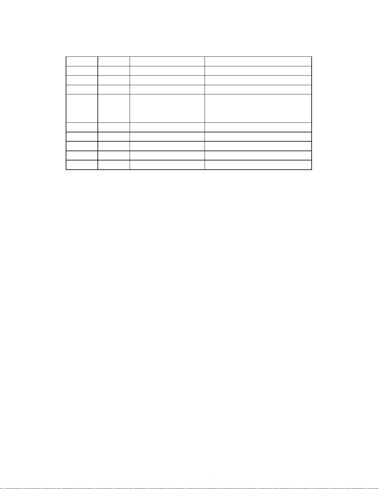
SPARE PARTS
(Refer to RD11-T-NPT-EXP drawing on previous page.)
MAINTENANCE
The Robo-Drain has been designed and continuously improved to provide many years of trouble-free service.
Most Robo-Drains outlast the life of the compressor that it is serving.
Still, the Robo-Drain is a mechanical device and routine inspection and maintenance are important and
recommended.
Weekly/Monthly
1. Use the test button to ensure the drain valve opens and closes.
2. Inspect interconnecting piping and tubing to ensure there are no leaks or damage.
Annually
1. Use the test button to ensure the drain valve opens and closes.
2. Inspect interconnecting piping and tubing to ensure there are no leaks or damage.
3. Replace Control Air Inlet Filter.
4. Check the four body bolts to ensure tight.
5. On the standard Robo-Drain with the translucent vessel, if the condensate level isn’t visible due to
vessel coated with contamination, it is recommended to remove the drain from service and follow the
simple disassembly instructions to permit the vessel to be thoroughly cleaned.
6. With the drain disassembled, exercise the float assembly to ensure it moves freely.
7. Again, with the drain disassembled, ensure the float is securely attached to the float bracket.
Item No.
Qty.
Part No.
Description
1
1
RDP-H2-KIT
Control Head Assembly
2
1
RDP-H1-KIT
Inlet Head Assembly
3
1
SSP-COCYL
Translucent Cylinder
4a
2
Cylinder O-Rings
4b
2/2
RDP-SEAL KIT
Trigger Assembly O-Rings
4c
1
Control Air Inlet Filter
5a,b
4/16
RDP-BOLT-KIT
Bolt/Nut Kit
6
1
RD11-FA1
Float and Trigger Block Assembly
7
1
RDP-FIT-KIT
Control Tubing Assembly
8
1
RDP-AC-KIT
Air Actuator Assembly
9
1
RDP-BV-KIT
Ball Valve Assembly

All design specifications subject to change without notice
© 2020 ASP-S-RD-411-101320
AIR SYSTEM PRODUCTS
51 Beach Avenue
Lancaster NY USA
P: +1 716-683-0435
www.airsyspro.com
Table of contents
Other Filtration Group Industrial Equipment manuals

Filtration Group
Filtration Group Air System Products Robo-Drain RD11-VAC User manual

Filtration Group
Filtration Group PuraShield Smart 500 User manual

Filtration Group
Filtration Group Air System Products Robo-Drain RD750 User manual

Filtration Group
Filtration Group Air System Products Robo-Drain RD13 User manual


