Hillco JS7020 User manual

Operator’s Manual
(SN23001-23999)
Model JS7020 & JS9020
Sidehill Leveling System
S650, S660, S670, S680 & S690
S760, S770, S780 & S790
D-171206CMA01C
September, 2022
WARNING
Read and understand
operator’s manual prior to
operating this equipment.
Failure to follow operation
instructions could result in
personal injury or damage to
the equipment.

Hillco Technologies, Inc.
2
D-171206CMA01C Sept, 2022
Hillco warrants its Class I products to be free from defects in material and workmanship for a period of
twelve (12) consecutive months following the warranty start date.
The warranty start date for Hillco products invoiced by Hillco from October 1
st
through May 31
st
is the first
day of June following the Hillco invoice date, or the first date of use, whichever is earliest. For Hillco products
invoiced by Hillco from June 1
st
through September 30
th
the warranty start date is the date of invoice. Once the
warranty period has begun, it cannot be stopped or interrupted.
Hillco warrants genuine Hillco replacement parts and components to be free from defects in material and
workmanship for a period of ninety (90) consecutive days following the Hillco invoice date, or the remainder of the
original equipment warranty period, whichever is longer.
Hillco’s obligation under this product and parts warranty shall be limited to repairing or replacing, free of
charge to the original purchaser, any part(s) that, in Hillco’s judgment, shows evidence of such defect. Hillco
additionally agrees to repair any physical damage to the product to which the Hillco product is directly attached
provided that the damage is directly attributable to a defect in the design or manufacture of the Hillco product, as
determined by Hillco, and that the damage occurs during the effective warranty period of the Hillco product.
Limitations to Warranty
This warranty does not cover:
1) Any product damaged by accident, abuse, misuse, negligence, or improper maintenance.
2) Any unauthorized product alteration or modification.
3) Any unauthorized repairs made with parts other than genuine Hillco parts unless specifically authorized by Hillco.
4) Any repairs performed by anyone other than Hillco or an authorized Hillco dealer unless specifically authorized
by Hillco.
5) Any claims directly resulting from improper installation, except those installations performed by Hillco.
Warranty Procedure
No warranty claims will be accepted without a completed Dealer PDI on file at Hillco.
For warranty submission instructions please email warranty@hillcotechnologies.com and request a
Warranty Claim Form. Complete the Warranty claim form and submit the claim, via email to
warranty@hillcotechnologies.com.
All warranty work must be performed, and claims submitted, within thirty (30) days of the occurrence of the
claim and within the warranty period.
All parts removed during warranty repair should be held for a period of sixty (60) days after the warranty
claim has been submitted to Hillco.
Hillco reserves the right to either inspect the product at the original retail purchaser's location, or the
authorized Hillco’s dealer's location; or require it to be returned to Hillco, transportation charges prepaid, for
inspection.
For additional details on Hillco’s Warranty Program refer to Hillco’s current “Warranty Policy Guide”.
Limitation of Liability
Hillco makes no express warranties other than those, which are specifically described herein. Any description of the
goods sold hereunder, including any reference to buyer's specifications and any descriptions in circulars and other media
published by Hillco is for the sole purpose of identifying such goods and shall not create an express warranty that the goods
shall conform to such description.
THIS WARRANTY IS EXPRESSLY IN LIEU OF ALL OTHER WARRANTIES EXPRESSED OR IMPLIED. There are no
implied warranties of merchantability or fitness for a particular purpose. This warranty states Hillco's entire and exclusive liability
and buyer's exclusive remedy for any claim for damages in connection with the sale or furnishing of Hillco products, their design,
suitability for use, installation, operation, or for any claimed defects herein. HILLCO WILL IN NO EVENT BE LIABLE FOR ANY
INCIDENTAL OR CONSEQUENTIAL DAMAGES WHATSOEVER, NOR FOR ANY SUM IN EXCESS OF THE PRICE
RECEIVED FOR THE GOODS FOR WHICH LIABILITY IS CLAIMED.
Neither representative of Hillco nor any dealer associated with Hillco has the authority to change the items of this
warranty in any manner whatsoever, and no assistance to purchaser by Hillco in the repair or operation of any Hillco product
shall constitute a waiver of the conditions of this warranty, nor shall such assistance extend or revive it.
Hillco reserves the right to make improvements in design or changes in specifications at any time, without incurring any
obligation to owners of units previously sold.
Statement of Limited Warranty
D-230314ADB01
Class I Warranty
Attached / Integrated Equipment, Parts, & Labor

Hillco Technologies, Inc.
3
D-171206CMA01C Sept, 2022
Contents
Model and Serial Number 1
Maximum Header Weights 1
Introduction 2
Safety 3
Signal Words................................................................................................................................... 3
Operation Safety..............................................................................................................................4
Hydraulic Safety...............................................................................................................................4
Service and Maintenance Safety..................................................................................................... 5
Highway Operation and Transport Safety........................................................................................5
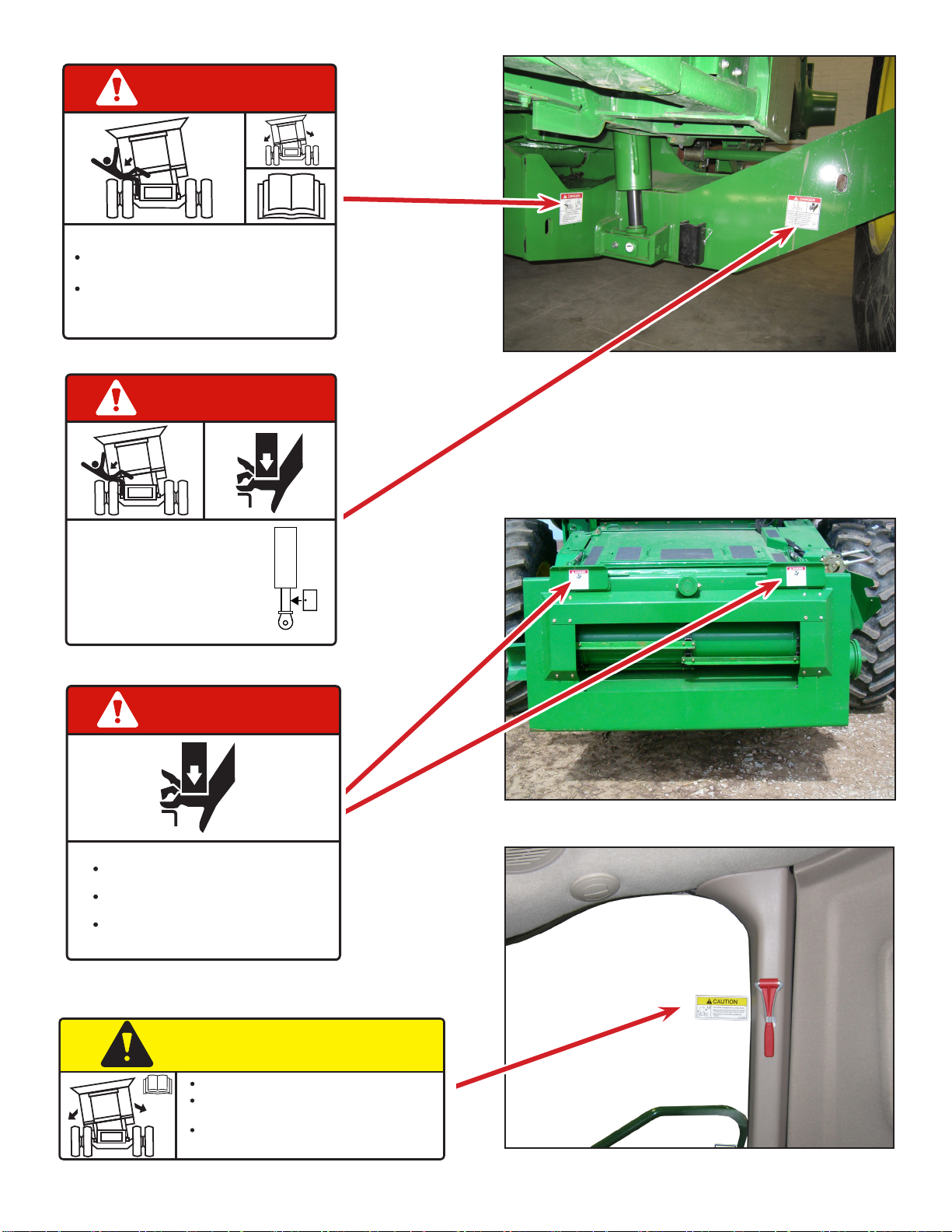
Safety Labels...................................................................................................................................6
Product Description 10
Controls and Components 11
Leveling Control Switches & Monitor............................................................................................. 11
Hydraulic Gear Pump.................................................................................................................... 12
JS9020 Hydraulic Flow..................................................................................................................12
Leveling Control Manifold..............................................................................................................12
Leveling Controller.........................................................................................................................13
Header Tilt Manifold.......................................................................................................................13
Overcarriage Position Indicator..................................................................................................... 14
Slope Sensing Clinometer............................................................................................................. 14
Transition.......................................................................................................................................14
Header Position Sensor.................................................................................................................15
Feeder Chain and Slats.................................................................................................................15
Feeder Drum Arms........................................................................................................................ 15
Retractable Ladder Step................................................................................................................15
Mechanical Leveling Cylinder Stops..............................................................................................16
Carriage.........................................................................................................................................16
Hydraulic Leveling Cylinders and Counter-Balance Valves ..........................................................17
Leveling Cylinder Safety Stops......................................................................................................17
Drop Axle......................................................................................................................................18
Header Tilt Control Switches......................................................................................................... 19
Header Tilt System........................................................................................................................ 19
Header Tilt Controls and Components.......................................................................................... 19
Operation 20
Leveling System Controls............................................................................................................. 21
Lateral Header Tilt / Contour Master............................................................................................. 22
Operator Adjustments....................................................................................................................24
Calibration..................................................................................................................................... 26
Diagnostics....................................................................................................................................33
Storage..........................................................................................................................................38
Transporting Combine on a Trailer................................................................................................ 38
Maintenance 39
Driveline Maintenance...................................................................................................................40
100 Hour - Annual Maintenance....................................................................................................41
Critical Joint Inspection..............................................................................................................42
Adjustments 44
Rear Axle Spacing.........................................................................................................................44
Lateral Tilt Flow Control Adjustment..............................................................................................48
Transition Fore/Aft Adjustment Procedure.....................................................................................48
Header Tilt Setup.......................................................................................................................... 49
Tire Selection 51
Header Tire Compatibility Chart............................................................................................................. 51
Header Compatibility Chart 52
Decal Placement.......................................................................................................................................53
Leveling System Specications 55
Electrical Schematics.............................................................................................................................. 57
JS7020 & JS9020 Leveling Electrical Schematic..........................................................................57
JS9020 Header Trim Schematic (Non Contour Master)................................................................61
JS5010 & JS7010 Header Trim Schematic (Non Contour Master)............................................... 62
Hydraulic Schematics 63
JS9020 Hydraulic (Leveling and Factory Header Trim).................................................................63
JS9020 Hydraulic (Leveling and Hillco Header Trim).................................................................64
JS5010 & JS7020 Hydraulic (Leveling and Header Trim)............................................................. 65
Notes 66

Hillco Technologies, Inc.
1
D-171206CMA01C Sept, 2022
Model and Serial Number
Maximum Header Weights
Write the serial number and the model number of the leveling system and combine on the lines provided.
It is important to reference these numbers when ordering parts or requesting technical support. We
suggest that you give the leveling system serial number to your John Deere dealer to be kept with their
combine serial number records.
Leveling System Model Number JS7020 JS9020
Leveling System Serial Number
Combine Model Number
Combine Serial Number
JS9020 11,700 lbs
JS7020 11,700 lbs
(circle one)
Hillco does not guarantee any non-John Deere header applications and will not be responsible for any
damage incurred from improper header congurations.
Please call Hillco Technologies if you have any questions regarding the JS7020 & JS9020 or any other
header conguration.

Hillco Technologies, Inc.
2
D-171206CMA01C Sept, 2022
Thank you for choosing the Hillco Technologies’ Sidehill Leveling System to compliment your farming
operation. This product has been designed and manufactured to meet the needs of farmers wanting to
increase the performance of John Deere S Series combines.
Safe, ecient and trouble free use of your Sidehill Leveling System requires that you, and anyone else
who will be operating or maintaining the leveling system, read and understand the safety, operation,
and maintenance information contained in the Operator’s Manual.
If extra copies of the operator’s manual are needed, contact Hillco at 1-800-937-2461 or download it
from Hillco Technologies’ website at www.hillcotechnologies.com
Introduction
Keep this manual handy for frequent reference and to pass on to new operators or owners. Call your
Hillco dealer or Hillco if you need assistance or information at 1-800-937-2461.
OPERATOR ORIENTATION – The directions left, right, front, and rear, as mentioned throughout this
manual, are as seen from the combine operator’s seat and facing in the direction of forward travel.

Hillco Technologies, Inc.
3
D-171206CMA01C Sept, 2022
SIGNAL WORDS
Note the use of the signal words DANGER, WARNING, and CAUTION with the safety messages. The
appropriate signal word for each message has been selected using the following guidelines:
DANGER - An immediate and specic hazard, which WILL result in
severe personal injury or death if the proper precautions are not taken.
WARNING - A specic hazard or unsafe practice, which COULD result in
severe personal injury or death if proper precautions are not taken.
CAUTION - Unsafe practices which COULD result in personal injury if
proper practices are not taken, or as a reminder of good safety practices.
NOTICE - is used to address practices not related to physical injury.
SAFETY ALERT SYMBOL
Safety
This Safety Alert symbol means
ATTENTION! BECOME ALERT! YOUR SAFETY IS INVOLVED!
The Safety Alert symbol identies important safety messages on the Hillco Leveling System and in
the manual. When you see this symbol, be alert to the possibility of personal injury or death.
Follow the instructions in the safety message.
DANGER
NOTICE
WARNING
CAUTION

Hillco Technologies, Inc.
4
D-171206CMA01C Sept, 2022
Operation Safety
1. Read and understand the Operator’s Manual and all safety labels before operating the leveling
system.
2. Make sure that all controls are in the manual position before starting the combine.
3. Clear the area of all bystanders, especially children, before starting the leveling system and during
operation.
4. Make sure all safety shields are in place before operating the combine. Never operate the ma-
chine with the shields removed.
5. Keep hands, feet, hair and clothing away from all moving and/or rotating parts.
6. Stay seated in the cab during operation.
7. Operate controls only when sitting in the seat of the combine.
8. To avoid engine damage, do not run the machine for extended periods of time when it is in the lev-
eled over position.
9. Always travel at a safe speed. Use caution when making turns or traversing ditches.
10.The leveling system is equipped with a maximum level warning lamp. This lamp indicates when
the machine has reached its maximum leveling capability. There are restrictions as to tread width
and tire selection for combines used in harvesting slopes greater than the maximum leveling ca-
pability of the leveling system.
11. The use of after-market grain tank extensions is prohibited from use on combines equipped with
Hillco Leveling Systems.
12.Level Limit Stops should be used on combines that rely on the limit switches to stop the leveling
prematurely to prevent sheet metal damage.
Hydraulic Safety
1. Do not search for high-pressure hydraulic leaks without hand and
face protection. A tiny, almost invisible leak can penetrate skin, there-
by requiring immediate medical attention.
2. Use cardboard or wood to detect leaks – never your hands!
3. Before inspecting the hydraulic system of the leveling system, install
the safety stops.
4. Before operating the leveling system, ensure that there are no ob-
structions between the chassis and the carriage.
5. Maintain proper hydraulic uid levels.
6. Ensure all ttings and hoses are in good repair.
7. Do not make any repairs to the leveling system hydraulic system
including: valves, hydraulic hoses, adapters, pumps, manifolds, or
reservoirs without rst contacting your authorized Hillco dealer.

Hillco Technologies, Inc.
5
D-171206CMA01C Sept, 2022
Service and Maintenance Safety
1. Review the Operator’s Manual and all safety items before servicing or maintaining the leveling
system.
2. Place the Auto/Manual leveling switch in the “Manual” position, stop the combine engine, wait
for any moving parts to stop, block the tires, the header, and the cylinder areas before servicing,
repairing, adjusting, or maintaining the leveling system.
3. Hydraulic oil is under pressure. Use caution when dealing with the hydraulic system.
4. Keep hands, feet, clothing and hair away from all moving and/or rotating parts.
5. Clear the area of bystanders, especially children, when carrying out any maintenance, repairs or
making any adjustments.
Highway Operation and Transport Safety
1. Check with local authorities regarding combine transport on public roads. Obey all applicable
regulations and laws.
2. Check clearance, elevations and widths of combine for travel near power lines, bridges, trees, etc.
3. Make sure the Auto/Manual leveling toggle switch is in the “Manual” position for all transport and
highway travel situations.
4. Always travel at a safe speed. Use caution when making corners or meeting trac.

Hillco Technologies, Inc.
6
D-171206CMA01C Sept, 2022
Familiarize yourself with the location of all safety labels. Read them carefully to understand the safe
operation of your machine.
Safety Labels
READ OPERATOR’S MANUAL SYMBOL
Decals, which display the Read Operator’s Manual
symbol, are intended to direct the operator to the
Operator’s Manual for further information regarding
maintenance, adjustments and/or procedures for
particular areas of the Leveling System. When a decal
displays this symbol refer to the Operator’s Manual for
further instructions.
TO APPLY NEW OR REPLACEMENT LABELS
1. Make sure the label area is smooth by removing any debris such as dirt or old labels.
2. Wash the area with soap and water and then dry it thoroughly.
3. After the area has completely dried, peal the backing o the safety label and place it onto the cleaned area.
4. Make sure all areas of the label have adhered to the machine by pressing down on the entire face of the
label, including the corners.

Hillco Technologies, Inc.
7
D-171206CMA01C Sept, 2022
DANGER
HYDRAULIC HAZARD
Loss of hydraulic pressure may cause
combine to tip.
Read operator’s manual before
disconnecting any hydraulic
components.
LL20-100788
DANGER
AVOID CRUSHING INJURY
Install safety stops on the
main leveling cylinders
before performing repair or
maintenance on the leveling
system to prevent accidental
tipping of combine chassis. LL-143621
DANGER
PINCH POINT HAZARD
Keep hands, feet and body away from
moving parts.
Do not stand or climb on machine
when operating.
Hazard occurs during leveling and
header trim.
LL20-100784
CAUTION
This machine is equipped with a Leveling System.
Make sure the Auto/Manual leveling control switch
is in the manual position before starting machine.
Read operator’s manual before operating this
machine. LL20-100782

Hillco Technologies, Inc.
8
D-171206CMA01C Sept, 2022
CAUTION
MOVING STEP HAZARD
Bottom step lowers and retracts upward.
Use caution when using ladder.
LL20-100785
DANGER
CRUSHING HAZARD
To prevent serious injury or death:
Keep all persons and objects clear
while any part of this machine is in
motion.
LL20-100783
CAUTION
LEVELING SYSTEM HAZARD
This machine is equipped with a leveling
system.
Combine chassis moves independent of
carriage.
Read operator’s manual and be aware
of hazardous areas at all times.
LL20-100787

Hillco Technologies, Inc.
9
D-171206CMA01C Sept, 2022
DANGER
HYDRAULIC HAZARD
Loss of hydraulic pressure may cause
combine to tip.
Read operator’s manual before
disconnecting any hydraulic
components.
LL20-100788
DANGER
AVOID CRUSHING INJURY
Install safety stops on the
main leveling cylinders
before performing repair or
maintenance on the leveling
system to prevent accidental
tipping of combine chassis.
LL-143621

Hillco Technologies, Inc.
10
D-171206CMA01C Sept, 2022
The Hillco Sidehill Leveling System is designed for John Deere S Series combines. Hillco designed the Sidehill
Leveling System to maintain the combine’s threshing capacity and harvesting eciency on contours of slopes up
to 18%. This leveling system is designed to be installed with little modication to the combine.
The Sidehill Leveling System tilts the combine’s chassis laterally, automatically compensating for slopes up to
18% as it moves across sloping terrain. The threshing platform remains level and allows both the combine and
the operator to perform at maximum eciency.
The leveling system uses a clinometer to sense the combine’s chassis position in relation to “level”. As the
combine moves onto a slope, the chassis leans out of level and the clinometer senses the deviation and sends
a signal the controller. The controller opens the appropriate leveling valve. The leveling valve allows hydraulic oil
to ow into the leveling cylinder. The cylinders tilt the combine’s chassis to correct for the tilt, bringing the chassis
back to level.
As the combine’s chassis levels, the master header tilt cylinder pushes hydraulic oil to the header tilt cylinder,
which counter-rotates the header to keep it parallel to the ground. The operator can manually adjust the header’s
position or, alternately, may use the combine’s original lateral tilt electronics and sensor-equipped header to
automatically compensate for varying ground contours.
Product Description
18% (10.2°)

Hillco Technologies, Inc.
11
D-171206CMA01C Sept, 2022
Controls and Components
Leveling Control Switches & Monitor
The leveling control switches (A) and Leveling
System Monitor (B) are located on the far side
of the John Deere Monitor.
Auto/Manual Leveling — The Auto/Manual
leveling button is used to toggle between the
Automatic and Manual Modes. In Manual Mode
the chassis will not rotate until initiated by the
operator. In Automatic Mode, rotation of the
chassis is initiated by the controller as dictated
by changes in the slope. The operator can
momentarily override the controller using the
Manual Left and Right Buttons. The combine
will return to level once the button is released.
On the lower right corner of the monitor the
leveling mode (Auto or Manual) is indicated.
Manual Tilt Left and Manual Tilt Right — These
buttons allow the operator to rotate the chassis
to the left or right as desired.
The monitor gives the operator feedback such
as:
Current Slope
Current Modes
Diagnostics
Alarms
The operate can adjust settings such as:
Left/Right Limits
Level Zero point
Manual Leveling Speed
Joystick calibrations
Detail description of the monitor and adjustable
settings are later in this manual.
For operation of the leveling system see the
Operation section.
A
B
Manual Tilt
Left
Manual Tilt
Right
Auto/Manual
Leveling
Auto/Manual
Leveling Mode
A - Leveling Control Switches
B - Leveling System Monitor
Ground Slope
0%
Home
Menu
Field
Auto
Home
Menu
Auto
MAX
Slope: 27

Hillco Technologies, Inc.
12
D-171206CMA01C Sept, 2022
JS9020 Hydraulic Flow
Hydraulic ow for the JS9020 leveling system
is supplied from the “T” located in the Deere
pressure supply line on the header height valve
block (B). This valve is located on the left side
of the combine below the cab. From this “T” oil
ows to the Hillco leveling valve located behind
the inspection door on the operator’s platform.
Oil is returned from the leveling valve to a “T”
located in the John Deere header height valve
block.
Leveling Control Manifold
The leveling control manifold (B) is located
behind the inspection door on the operator’s
platform. The operator electronically activates
the manifold by either pushing the manual
leveling buttons or having it in automatic mode.
The manifold diverts hydraulic ow to the
corresponding leveling cylinder to rotate the
chassis.
C
B
JS9020 Only
B - Header Height Valve Block
C - Leveling Manifold
Hydraulic Gear Pump
The JS7020 has a Hydraulic Gear Pump (A)
that is mounted directly to the output shaft of the
combine’s rear engine housing. It provides the
necessary hydraulic ow to operate the leveling
systems functions. The gear pump isolates
the leveling system’s hydraulic ow from the
remaining combine’s hydraulics.
A
JS7020 Only
A - Gear Pump

Hillco Technologies, Inc.
13
D-171206CMA01C Sept, 2022
Leveling Controller
The electronic leveling controller (A) is located
behind the inspection door on the operator’s
platform above the leveling manifold. The
controller processes slope information and
outputs signals to the hydraulic leveling valve.
When auto leveling is activated the leveling
controller levels the chassis up to a maximum
slope of 27%.
Header Tilt Manifold
Located on the left side of the feeder house is the
header tilt manifold. This manifold diverts ow
to the cylinder in the feeder house pivoting the
header. The hydraulic valve fully integrates with
the combine’s electronics to provide auto lateral
tilt. If the combine was originally equipped with
Contour Master then the stock valve is used to
control the header tilt.
A
B - Leveling Controller
B - Header Trim Manifold
B
C - Undercarriage Position Indicator
C
Overcarriage Position Indicator
Attached to the overcarriage and undercarriage
is the position indicator (C). The position
indicator outputs a signal to the controller
of the overcarriage position relative to the
undercarriage. This also acts as a maximum
level indicator. When the combine is nearing
maximum level the controller reduces the amps
to the leveling valve decreasing the hydraulic
ow. This provides for smooth leveling when
achieving maximum level.
D - Transition Position Indicator
D
Header Position Sensor
Located on the right side of the transition is
the header position indicator (D). It utilizes a
linkage between the face plate and the transition
to indicate the header position relative to the
combine. The position is then displayed in the
corner post of the cab.

Hillco Technologies, Inc.
14
D-171206CMA01C Sept, 2022
Slope Sensing Clinometer
Located on the overcarriage near the
Overcarriage Position Indicator is the Slope
Sensing Clinometer (A). This clinometer outputs
a signal to the controller. This output is a value
that tells the controller the chassis’ position
relative to level.
B - Transition
A - Slope Sensing Clinometer
Transition
The transition is added to the front of the feeder
house to pivot the header and allow it to follow
the contour of the ground.
B
A
Feeder Chain and Slats
The feeder chain is extended and slats are
added to accommodate the increased feeder
house length.
Specications
Acorn Nut on Feeder Chain 40N*m/30lb-ft
Chain Slat Hardware 40N*m/30lb-ft
Feeder Drum Arms
Hillco provides longer feeder drum arms that
accommodate the increased length of the feeder
house.
C - Slat
D - Acorn Nut
E - Drum Arm
D
C
E

Hillco Technologies, Inc.
15
D-171206CMA01C Sept, 2022
Retractable Ladder Step
All sidehill combines are equipped with a
retractable bottom step.
If the ladder does not extend and retract properly
check the fasteners in all of the pivot locations
and make sure they are not over tightened.
Over tightening of these fasteners will cause the
ladder to bind. Make sure that the gas-charged
struts (D) keep the ladder fully retracted. Replace
the struts if they appear to be weak. If the ladder
does not fully retract, permanent damage may
occur during eld operation.
D - Gas-charged Struts
Use of the double rubber step may cause
ladder damage if the rubber step drags on the
ground. Damage due to the ladder contacting
the ground is not covered by Hillco’s warranty.
If operator chooses to operate the combine
with the double rubber step the combine must
maintain at least 12” between the step and
the ground when the combine is fully leveled
to the ladder side.
Damage may occur if ladder is pivoted forward
and the rubber step contacts the header or
driveline
D
WARNING
WARNING

Hillco Technologies, Inc.
16
D-171206CMA01C Sept, 2022
Mechanical Leveling Cylinder Stops
Some tire congurations may come into contact
with the side panel when the combine is leveled
over. Limit switches will prevent this contact,
however, Hillco requires installing mechanical
leveling cylinder stops. This will prevent damage
in the event of hydraulic or electrical failure. After
setting the carriage angle limits verify there is 1”
between the tire and the closest contact point
or 1/4” between the driveshafts and the leveling
system chassis. Add cylinder stops to prevent
the cylinder from over-leveling the combine.
Contact Hillco for these cylinder stops.
Carriage
The carriage is designed to support the
combine’s chassis while allowing the combine
to rotate through full range of motion. It consists
of an undercarriage and an overcarriage. The
drive wheels, nal drives, and transmission are
mounted to the undercarriage. The overcarriage
bolts to combine’s axle and chassis. The
leveling cylinders connect to the overcarriage
and the undercarriage. The carriage raises
the combine chassis seven inches to prevent
the tires from coming into contact with the side
panels.
B - Transmission
C - Overcarriage
D - Undercarriage
E - Counter-Balance Valve
F - Leveling Cylinders
B
D
C
A - Mechanical Leveling Cylinder Stops
5/8 inch - Part # MC-137251
1/8 inch - Part # MC-137501
A
Set Carriage Angle Limits prior to
installing Leveling Cylinder Stops.
Notice

Hillco Technologies, Inc.
17
D-171206CMA01C Sept, 2022
B
A
Leveling Cylinder Safety Stops
When the leveling cylinder safety stops are installed
on the leveling cylinders, the carriage cannot
rotate. The stops must be installed before working
on or around the leveling system and when hauling
the combine. It is recommended that the stops be
inserted during long-term storage. When the stops
are not being used, they should be stored on the
mount next to the leveling cylinder.
C - Cylinder Safety Stops
D - Cylinder Safety Stop Holder
A - Cylinder
B - Counter Balance Valve
Install the cylinder stops before working on
or around the leveling system. Failure to
install the cylinder stops before working on
or around the leveling system may result in
sudden chassis rotation.
D
C
Hydraulic Leveling Cylinders and
Counter-Balance Valves
JS7020 & JS9020
There are two leveling cylinders (A) located on the
rearward side of the leveling system’s carriage.
These cylinders are pressurized by the leveling
hydraulic valve to tilt the combine chassis to correct
for slope changes. Both leveling cylinders are
equipped with built in hydraulic counter-balance
valves (B) that positively lock the oil into the cylinders
until a pressure signal is sent from the hydraulic
leveling valve. These counter-balance valves lock
the chassis position in the event of hydraulic hose
failure.
WARNING
This manual suits for next models
1
Table of contents
Other Hillco Farm Equipment manuals