AG SHIELD 12-46-3 User manual


AG SHIELD LTD.
BOX 9, BENITO, MANITOBA CANADA R0L 0C0
Phone 1-800-561-0132 or 204-539-2000 Fax 204-539-2130
www.agshield.com E-mail: office@agshield.com
Warranty Registration Form - Warranty registration must be filled out by the dealer at the time
of delivery, and emailed, faxed, or mailed to Ag Shield within 10 days of customer invoice to validate warranty.
Machine type-e.g. Recon, Land Roller
Model - e.g., 400 or 12- 46- 3
Delivery Date
Serial Number e.g. 1815125
Size - e.g. 7 ft or 46 ft
Options
Additional Serial Number e.g. 1415103
Size - e.g. 7 ft or 46 ft
Options
Customer Name
Phone Number
Mailing Address
City
State / Province
Country
Postal Zip code
Email Address for service & updates- required
Customer agrees that the equipment was complete with all parts in good working order except as noted
below, that the customer has received the owner’s handbook, and the customer has been thoroughly
instructed in the use of it. Customer agrees that they have been instructed in the care, adjustments, the
safe operation of the machine, and the applicable warranty policy. Max lo dot the tires has been
identified.
Dealer Name
Phone Number
Mailing Address
City
State / Province
Country
Postal Zip Code
Email Address for service & updates- required
Dealer agrees to have thoroughly instructed the customer on the above described equipment,
including the contents of the Owner’s Handbook, equipment care, adjustments, safe operation, and
applicable warranty policy.
Signature: __________________________________________
Date:_______________________________________________
enter X
enter X

PAGE 4
1.INSPECTION
PRE-DELIVERY INSPECTION CHECK LIST
General
Remove wrapping and wash unit, removing all road debris. (Road salt, mud, snow, etc)
Inspect paint, decals and general appearance of unit.
Verify that the owner’s manual is in the manual storage tube.
Verify “SLOW MOVING VEHICLE” sign (SMV) is on unit.
Verify that the jack is with the unit and function properly.
Check wheel bolts for proper torque, proper wheel size and all tires are the same make.
Check for proper tire pressure (PSI)
Verify that locking pins are in place.
Lubricate all components as per operator’s manual recommendation.
Check that all bolts and fasteners are at the proper torque specifications.
Check locking collars and set screws for proper torque.
Verify operation of lights.
Verify the unit moves “IN” and “OUT” of transport without binding.
Hydraulics
Ensure that all hydraulic hoses and lines are routed properly and secured.
Verify that all hydraulic fittings / hoses are secure and there are no oil leaks.
Inspect all cylinders for leakage and the cylinder shaft for rust, pits, or scratches.
Verify operation of all hydraulic functions –Cycle hydraulic cylinders to remove air from the system.
Delivery
Verify that the customer is aware of warning decals and proper jack placement for transport.
Verify that the customer is aware of proper operation and transportation of the unit.
Verify that the customer has received an operator’s manual.
Explain all maintenance and service intervals to the customer (From operations manual).
Advise the customer of grease locations and maintenance schedules.
Level the unit per operator’s manual and instruct the customer on proper procedures.
Date: _________________________Signature of Technician who performed the inspection: ________________________

PAGE 5
2.TABLE OF CONTENTS
1. INSPECTION........................................................................................................................4
2. TABLE OF CONTENTS .......................................................................................................5
3. INTRODUCTION AND SIGN-OFF FORM............................................................................6
4. SPECIFICATIONS................................................................................................................7
5. SAFETY................................................................................................................................9
5.1. SAFETY OVERVIEW.................................................................................................................10
5.2. GENERAL SAFETY...................................................................................................................10
5.3. MAINTENANCE SAFETY.......................................................................................................... 11
5.4. HYDRAULIC SAFETY...............................................................................................................11
5.5. STORAGE SAFETY................................................................................................................... 11
5.6. TRANSPORT SAFETY..............................................................................................................11
5.7. REFUELING SAFETY................................................................................................................ 12
5.8. TIRE SAFETY............................................................................................................................12
5.9. IN FIELD OPERATION.............................................................................................................. 12
5.10. SAFETY DECALS ..................................................................................................................... 13
6. SETUP FROM SHIPPING MODE.......................................................................................14
6.1. TRUCK SHIPPING..................................................................................................................... 14
6.2. EXAMPLES OF THE FOUR (4) POINT HITCH LIFT SETUP..................................................... 14
6.3. TOWED OUT SHIPPING ........................................................................................................... 14
7. MAINTENANCE .................................................................................................................15
8. OPERATION......................................................................................................................16
8.1. EASIFOLD - FOLDING FROM ROAD TO FIELD. ..................................................................... 16
8.2. “EASIFOLD” FOLDING FROM FIELD TO ROAD PROCEDURE ............................................. 19
8.3. LEVELING BLADE OPERATION (FOR MODELS WITH A LEVELING BLADE)...................... 22
8.4. WATER FILLING ROLLER TANK............................................................................................. 25
8.5. ACRE METER OPTION.............................................................................................................26
9. PARTS................................................................................................................................27
9.1. 60 FT LANDROLLER 800019.................................................................................................... 27
9.2. HITCH - 831009......................................................................................................................... 28
9.3. CENTER ASSEMBLY 800019................................................................................................... 29
9.4. CENTER ASSEMBLY 801737................................................................................................... 30
9.5. WING ASSY LH 60 FOOT LAND ROLLER 800019 .................................................................. 31
9.6. LH WING ASSEMBLY 802374 .................................................................................................. 33
9.7. WING ASSY RH 60 FOOT LAND ROLLER 800019.................................................................. 34
9.8. RH WING ASSEMBLY 802370..................................................................................................36
9.9. DECALS LOCATIONS AND PART NUMBERS.........................................................................37
9.10. BOLT HUB ASSEMBLY 113686 ............................................................................................... 38
10. HYDRAULIC SCHEMATICS, HOSE SPECIFICATIONS...................................................39
10.1. HYDRAULIC SCHEMATIC 60 FT ROLLER .............................................................................. 39
10.2. BOLT GRADE CHART ..............................................................................................................41
10.3. BOLT TORQUE CHART............................................................................................................ 42
11. WARRANTY.......................................................................................................................43

PAGE 6
3.INTRODUCTION AND SIGN-OFF FORM
Congratulations! on your choice of an Ag Shield Land Roller. This equipment has been designed and
manufactured to meet the needs of the discerning farmers and contractors, and rental agencies.
OPERATOR ORIENTATION - The directions left, right, front and rear, as mentioned throughout this manual,
are as seen from the tractor driver's seat and facing in the normal direction of travel.
Ag Shield follows the general safety standards specified by the American Society of Agricultural Engineers (ASAE)
and the Occupational Safety and Health Administration OSHA). Anyone who will be operating and/or maintaining the
Ag Shield Land Roller must read and clearly understand ALL Safety, Operating, and Maintenance information
presented in this manual.
Do not operate or allow anyone else to operate this equipment until such information has been reviewed. Review this
information annually before season start-up. Make these reviews of safety and operation a standard practice for all
your equipment. An untrained operator is not qualified to operate this machine.
A sign off sheet is provided for your record keeping showing that all personnel who will be working with the equipment
have read and understood the information in the Operators Handbook and have been instructed in the operation of
the equipment.
SIGN-OFF FORM
DATE
OPERATORS SIGNATURE
EMPLOYERS SIGNATURE

7
4.SPECIFICATIONS

8

9
5.SAFETY
SAFETY ALERT
SYMBOL
This Safety Alert symbol means:
ATTENTION! BECOME ALERT!
YOUR SAFETY IS INVOLVED!
The Safety Alert symbol identifies important
safety messages on the Ag Shield Land Roller
and in the manual. When you see this symbol,
be alert to the possibility of personal injury or
death. Follow the instructions in the safety
message
Accidents Disable and Kill
3 Big Reasons
Accidents Cost
Accidents Can Be Avoided
SIGNAL WORDS:
Note the use of the signal words DANGER, WARNING and CAUTION with the safety messages. The appropriate
signal word for each message has been selected using the following guidelines:
DANGER -Indicates an imminently hazardous situation that, if not avoided, will result in death or serious injury.
This signal word is to be limited to the most extreme situations typically for machine components,
which for functional purposes, cannot be guarded.
WARNING - Indicates a potentially hazardous situation that, if not avoided, could result in death or serious injury,
and includes hazards that are exposed when guards are removed. It may also be used to alert
against unsafe practices.
CAUTION - Indicates a potentially hazardous situation that, if not avoided, could result in minor injury. It may also
be used to alert against unsafe practices.

10
5.1. SAFETY OVERVIEW
YOU are responsible for the SAFE operation and maintenance of your Ag Shield Land Roller. YOU must ensure that
you and everyone who is going to operate maintain or work around the Land Roller be familiar with the operating and
maintenance procedures and related SAFETY information contained in this manual. This manual will take you step-by-
step through your working day and alerts you to all good safety practices that should be adhered to while operating the
Land Roller.
Remember, YOU are the key to safety. Good safety practices not only protect you but also the people around you.
Make these practices a working part of your safety program. Be certain that EVERYONE operating this equipment is
familiar with the recommended operating and maintenance procedures and follows all the safety precautions. Most
accidents can be prevented. Do not risk injury or death by ignoring good safety practices.
•Land Roller owners must give operating instructions to operators or employees before allowing them to operate the
Land Roller, and at least annually thereafter per OSHA regulation 1928.57.
•The most important safety device on this equipment is a SAFE operator. It is the operator's responsibility to read
and understand ALL Safety and Operating instructions in the manual and to follow these. All accidents can be
avoided.
•A person who has not read and understood all operating and safety instructions is not qualified to operate the
machine. An untrained operator exposes himself and bystanders to possible serious injury or death.
•Do not modify the equipment in any way. Unauthorized modification may impair the function and/or safety and could
affect the life of the equipment.
•Think SAFETY! Work SAFELY!
5.2. GENERAL SAFETY
1) Read and understand the Operator's Manual and all safety signs before operating,
maintaining, adjusting or transporting the Land Roller.
2) Only trained competent persons shall operate the Land Roller. An untrained operator is not
qualified to operate the machine.
3) Have a first-aid kit available for use should the need arise and know how to use it.
4) Have a fire extinguisher available for use should the need arise and know how to
use it.
4. Do not allow riders.
5. Wear appropriate protective gear. This list includes but is not limited to:
•A hard hat
•Protective shoes with slip resistant soles
•Protective glasses or goggles
•Heavy gloves
•Hearing protection
6. Stop the engine, place all controls in neutral, set park brake, remove ignition key and wait
for all moving parts to stop before servicing, adjusting, repairing or unplugging.
7. Review safety related items with all personnel annually.

11
5.3. MAINTENANCE SAFETY
1) Review the Operators Manual and all safety items before working with, maintaining or operating the Land Roller.
2) Stop the tractor engine, place all controls in neutral, set park brake, remove ignition key, wait for all moving parts to
stop before servicing, adjusting, repairing or unplugging.
3) Before applying pressure to a hydraulic system, make sure all components are tight and that steel lines, hoses and
couplings are not damaged.
4) Relieve pressure from hydraulic circuit before servicing or disconnecting from tractor.
5) Keep hands, feet, clothing and hair away from all moving and/or rotating parts.
6) Clear the area of bystanders, especially children, when carrying out any maintenance and repairs or making any
adjustments.
7) Place stands or blocks under the frame before working beneath the machine.
5.4. HYDRAULIC SAFETY
1) Always place all tractor hydraulic controls in the off position before dismounting.
2) Make sure that all components in the hydraulic system are kept in good condition and are clean.
3) Replace any worn, cut, abraded, flattened or crimped hoses and steel lines.
4) Do not attempt any makeshift repairs to the hydraulic lines, fittings or hoses by using tape, clamps or cements. The
hydraulic system operates under extremely high-pressure. Such repairs can fail suddenly and create a hazardous
and unsafe condition.
5) Wear proper hand and eye protection when searching for a high-pressure hydraulic leak. Use a piece of wood or
cardboard as a backstop instead of hands to isolate and identify a leak.
6) If injured by a concentrated high-pressure stream of hydraulic fluid,
seek medical attention immediately. Serious infection or toxic reaction
can develop from hydraulic fluid piercing the skin surface.
5.5. STORAGE SAFETY
1) Store unit in an area away from human activity.
2) Do not permit children to play on or around the stored Land Roller.
3) Store in a lower position so persons cannot be injured, or property cannot be damaged by mechanical failure.
5.6. TRANSPORT SAFETY
1) Read and understand ALL the information in the Operator's Manual regarding procedures and SAFETY when
operating the Land Roller in the field and/or on the road.
2) Check with local authorities regarding machinery transport on public roads. Obey all applicable laws and
regulations.
3) Always travel at a safe speed. Use caution when making corners or meeting traffic.
4) Make sure the SMV (Slow Moving Vehicle) emblem and all the lights and reflectors that are required by the local
highway and transport authorities are in place, are clean and can be seen clearly by all overtaking and oncoming
traffic. Daybreak and dusk are particularly dangerous and pilot vehicles are recommended.
5) Ensure that the Land Roller is hitched positively to the towing vehicle. Always use a safety chain between the
machine and the tractor.
6) Keep to the right and yield the right-of-way to allow faster traffic to pass. Drive on the road shoulder, if permitted by
law.
7) Always use hazard warning flashers on the Land Roller when transporting unless prohibited by law.
8) Install cylinder stops/transport lock brackets and close valves in hydraulic lines before transporting or working under
the frame.
9) It is recommended that only 3/4 tonne or larger capacity trucks be used for towing on the road. This size of truck
plus careful driving will provide recommended stability and control when towing.

12
5.7. REFUELING SAFETY
1) Handle fuel with care. It is highly flammable.
2) Do not refuel the machine while smoking or when near open flame or sparks
3) Stop engine before refueling. Clean up spilled fuel before restarting engine.
5.8. TIRE SAFETY
1. Failure to follow proper procedures when mounting a tire on a wheel or rim can produce an explosion, which may
result in serious injury or death.
2. Do not attempt to mount a tire unless you have the proper equipment and experience to do the job.
3. Have a qualified tire dealer or repair service perform required tire maintenance.
4. Operate the tires at the pressures, loads, and speeds suggested by the manufacturer.
5. Operate the tires at the pressures, loads, and speeds suggested by the manufacturer.
5.9. IN FIELD OPERATION
1. Read and understand the Operator’s Manual and all safety signs before using.
2. Lower machine to the ground, place all controls in neutral, stop engine, set park brake, remove ignition key, and
wait for all moving parts to stop before servicing, adjusting, repairing or unplugging.
3. Keep hands, feet, hair and clothing away from all moving and/or rotating parts
4. Be familiar with all potential hazards: trees, rocks ditches, gullies, etc. Plan your route to avoid hazards. Keep
Land Roller width in mind when maneuvering to avoid obstacles.
5. Fasten seatbelt.
6. Max speed of 10 km/hr (6 MPH).
7. Be aware of sharp turns/jackknifing.
8. Be aware of surroundings and blind spots when reversing.
9. DO NOT exceed max hitch weight capabilities of your tractor.
10. Attach safety chains.
11. Make certain the tractor pin fits hitch perfectly.
12. Do not allow riders on the Land Roller or tractor during operation or transporting.
13. Clear the area of all bystanders, especially children, before starting.
14. Stay away from all frames and components when folding or extending. Keep others away.
15. Before applying pressure to the hydraulic system, make sure all components are tight and that steel lines, hoses
and couplings are not damaged.
16. Review safety instructions annually

13
5.10. SAFETY DECALS
The various safety decals, and their locations on the equipment are shown in the illustrations to follow. Good safety
practices require familiarizing yourself with the decals. Read the warning messages, and note the area, or specific
function related to that area, that the decal highlights. If safety decals have been damaged, removed, become
illegible, or replacement parts do not have the decal; new ones must be applied. Safety decals are available from your
authorized dealer. Ag Shield reserves the right to update safety decals without notice. Safety decals may not be to
scale or exactly as shown.
14
6.Setup from Shipping Mode
6.1. TRUCK SHIPPING
There are many variations to truck shipping Refer to instructions delivered with your shipment
Items required or preferred for setup
1. Forklift rated 6000 pounds or more.
2. Tractor with hydraulic system to raise and lower the machine, as required.
3. Hand tools
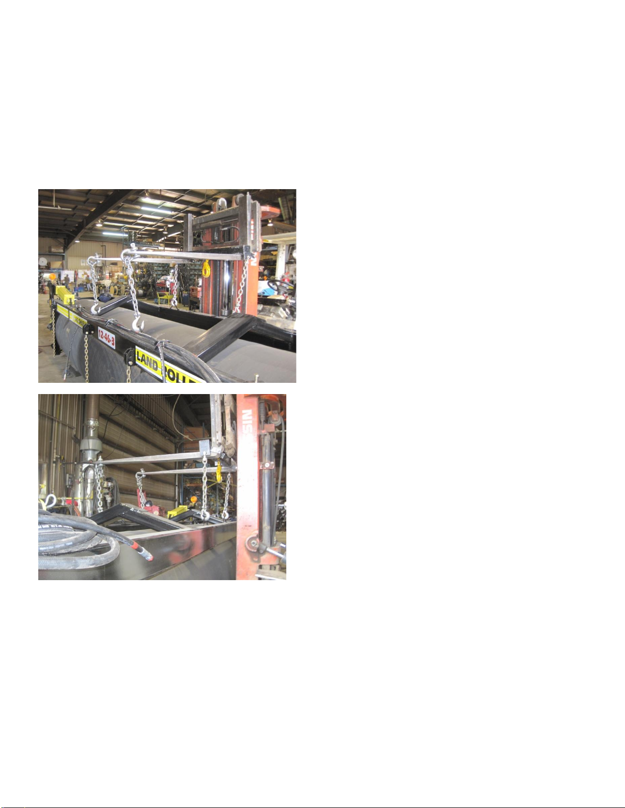
6.2. EXAMPLES OF THE FOUR (4) POINT HITCH LIFT SETUP
6.3. TOWED OUT SHIPPING
Towed out units should be field ready, Follow the inspection instructions included in this manual.

15
7.MAINTENANCE
General
•Repack the wheel hubs after the first 500 travel miles; then yearly thereafter.
•Visually inspect the wheel bolts for tightness each day. (See torque Specifications)
Every 10 hours (Daily)
•Grease all pivot points
Every 100 hours (Monthly)
•Visually inspect hydraulic hoses & fittings for leaks or damage.
•Inspect lighting system and electrical harness for damage.
Annually (or every 300 hours)
•Inspect wheel bearings / hubs and grease.
•Grease roller bearings.
•Check wheel bolts and re-torque.
•Check tire pressure, follow tire manufactures inflation recommendations.
•Visually inspect unit for loose, worn, or damaged components.
16
8. OPERATION
DANGER
WATCH FOR PEDESTRIAN TRAFFIC-
8.1. EASIFOLD - FOLDING FROM ROAD TO FIELD.
EasiFold is the standard Ag Shield configuration where each outer wheel is rotated 25-45 degrees by a
hydraulic cylinder, and the operator must then back up the whole unit to have the wings fold out behind the
center section to the field position.
There are 2-3 hydraulic circuits on all Ag Shield: Land Rollers:
A. This first circuit (WHITE / GREEN COLOUR) hereafter on “Lever 1” that turns the wheels so that a
backing up motion will move the Land Roller wings to field position.
B. The second circuit (RED AND BLUE COLOUR) (Lever2) that raises or lowers the center and outer
wheels for road transport and is teed together with the diagonal arm locking function, the hydraulic
hitch locking cylinder.
C. The third (optional) circuit (YELLOW/BLACK COLOUR) (Lever3) that raises and lowers the land
leveling blade.
1) Chose a reasonably level location with no bystanders or small children in the vicinity.
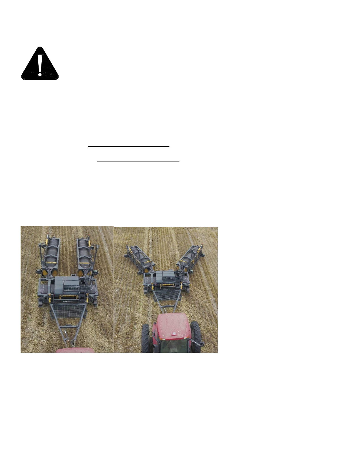
2) Operate the whole unit in a forward direction until the wings are trailing out behind the center section at
an equal and perpendicular angle to the center section.
FIGURE 1 WINGS TRAILING DIRECTLY BEHIND & STARTING TO UNFOLD
3) Operate Lever 2 to raise the rollers up ALL the Way to top to allow transport locks to be removed.
4) If so equipped, use lever 3 to raise the leveling blade to the highest position.
5) Set parking brake, place tractor transmission in Neutral, leave the tractor cab tractor,
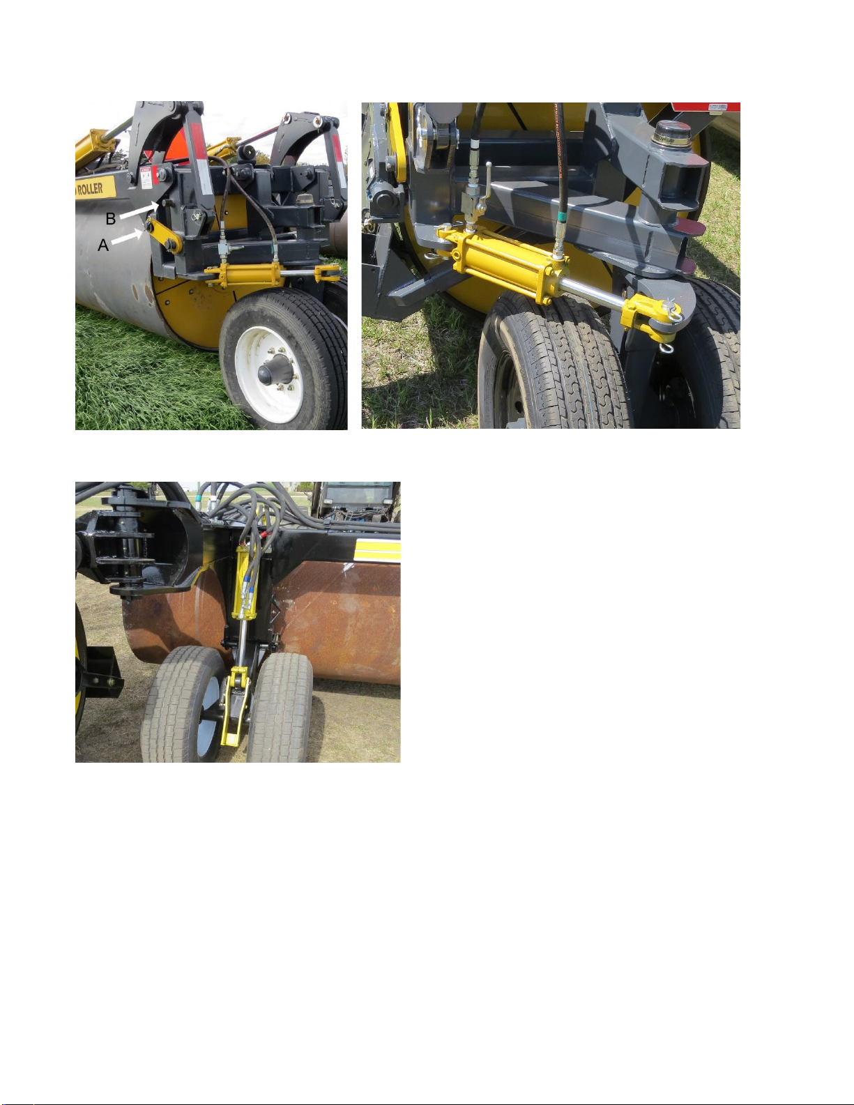
6) Remove the road transport locks from front floating hitch cylinders.

17
FIGURE 2 CYLINDER LOCKS FOR FLOATING HITCH
7) Remove the Floating Hitch pins and place them into their holders.
8) Unlock the hydraulic valve for the Diagonal Pull Arm
FIGURE 3 FLOATING HITCH PIN REMOVED & HYD VALVE FOR DIAG ARM
18
10)Unlock the Yellow Rear Transport From Pin A to B
11)Unlock the Rear Wheel Pivot Hydraulic Valve.
FIGURE 4 REAR TRANSPORT LOCK & REAR HYD VALVE
12)Remove the Yellow cylinder locks on the center section wheels, both LH and RH.
FIGURE 5 CENTER WHEELS UNLOCKED
13)Repeat Steps 6 Through 10 on the RH side of the machine
14) Enter tractor cab, operate lever 1 to rotate the outer wheels to angled position stop on the cylinder.
15) Carefully back up the unit until the wings are running parallel with the center section DO NOT
CONTINUE TO BACK UP IF ONE WING IS NOT SQAURE. as wheel and frame damage will result.
Instead pull ahead and get the 2 wings to be similar then attempt again.
16) Move Lever 1 to rotate the wheels back to the road position
17) Move lever 2 to lower the rollers to the ground and raise the wheels completely up into field operation
position.
18) Observe that the diagonal pulling arms are fully rotated into the slots on front corner of both ends of the
center section.
19) Observe that the front floating hitch cylinder has moved to fully retracted position. The hitch is free to
float as the roller follows ground contours.
19
20) Set parking brake, place transmission in neutral, exit the cab.
21) Remove the pin from the floating hitch tab, and place in the holding socket provided, place retaining key
through end of pin. (See Figure 3)
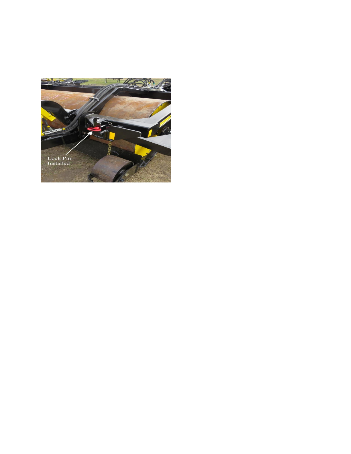
22) Normally the locking pins that hold diagonal arms into the slots on front of frame are not required. The
diagonal pulling arms will stay in the slots during field work. However, if your tractor hydraulics and field
conditions combine to have the diagonal pulling arm rise out of the slots while travelling across the field,
now is the time to install the retaining pins above the diagonal pulling bar.
FIGURE 6 PIN FOR DIAGONAL PULL ARM IN LOCKED POSITION
23)Enter the cab, lower the leveling blade if desired, and begin to smooth and firm your field to perfection.
24)Maximum speed selection depends upon field conditions. Mellow fields with corn root balls and few 8-
inch diameter stones may rolled at 5-8 mph. When using the leveling blade to move several inches of
earth, 3-4 mph is THE MAXIMUM SPPED, even less if there are a lot of larger square cornered stones
protruding out of the ground. If there are a lot of 8-inch diameter stones, speeds above 7 mph may dent
the rollers. Rollers with Leveling blades MUST operate slower than rollers without leveling blades.
8.2. “EASIFOLD” FOLDING FROM FIELD TO ROAD PROCEDURE
1. Chose a reasonably level location with no bystanders or children in the vicinity.
2. Move lever 1 to confirm that the outer wheels are rotated to the road position.
3. If so equipped use lever 3 to raise the leveling blade to the highest position.
4. If diagonal pull arm locks were inserted, set parking brake, place tractor transmission in Neutral, leave
the tractor cab tractor, remove the diagonal arm lock pins.
5. Enter tractor cab.
6. Operate Lever 2 to raise the rollers up ALL the Way to top to allow transport locks to be engaged.
7. Observe that the diagonal pull arms have risen to road position.
8. Observe that the front floating hitch cylinder has been fully extended.
9. Set parking brake, place tractor transmission in Neutral, leave the tractor cab tractor,

20
10. Engage the road transport locks on the front hitch
11. Install the floating hitch pins for transport
FIGURE 7 TRANSPORT LOCKS FOR HITCH FIGURE 8 FLOATING HITCH PINS LOCKED
12. Move the diagonal arm hydraulic valve into the locked position.
13. Place the outer wheel yellow lock back onto pin A
FIGURE 9 DIAGONAL ARM LOCKED FIGURE 10 OUTER WHEEL LOCKED IN TRANSPORT
This manual suits for next models
2
Table of contents
Other AG SHIELD Farm Equipment manuals


