Hills DAS ComNav User manual


1Hills – ComNav User Manual V1.3 www.das.com.au
Table of Contents
Introduction ...................................................................................................................................... 4
Warning............................................................................................................................................. 5
Warranty............................................................................................................................................ 5
Glossary of terms............................................................................................................................. 6
Legend .............................................................................................................................................. 7
Feature & Benefits ........................................................................................................................... 8
1. Phone Line connection............................................................................................................... 8
2. Phone Line connection, and network connection....................................................................... 9
3. Phone Line connection, network connection and integrated into the door intercom system. ....9
4. Phone Line connection, network connection, integrated into the door intercom system with
VoiceNav code pads. ..................................................................................................................... 9
Accessing the ComNav – Via a Touch Tone Phone ................................................................... 10
Main Menu – Structure...................................................................................................................11
Main Menu – explained .................................................................................................................. 12
System Status ..............................................................................................................................12
System Control.............................................................................................................................12
Security System Status..................................................................................................... 12
Area Control...................................................................................................................... 12
To Control Zone Bypass ................................................................................................... 12
Event History .................................................................................................................... 12
Intercom Control...........................................................................................................................12
To commence listen in mode............................................................................................ 12
To commence two – way communication mode............................................................... 12
Output Control .............................................................................................................................. 13
Select an output................................................................................................................ 13
Message Bank..............................................................................................................................13
Exit message ....................................................................................................................13
Entry Message.................................................................................................................. 13
System Configuration...................................................................................................................14
User configuration.............................................................................................................14
User Pin ....................................................................................................................14
User Area ..................................................................................................................14
User Authority ........................................................................................................... 14
Time and date................................................................................................................... 14
Time ..........................................................................................................................14
Date........................................................................................................................... 14
Phone number configuration............................................................................................. 15
Alarm Phone numbers, 1, 2 & 3 ................................................................................ 15
Divert phone numbers 1, 2 & 3 ................................................................................. 15

2Hills – ComNav User Manual V1.3 www.das.com.au
SMS phone numbers 1, 2 & 3 ................................................................................... 15
Voice message recording ................................................................................................. 16
Exit message............................................................................................................. 16
Entry message ..........................................................................................................16
User name................................................................................................................. 16
Zone name ................................................................................................................16
Area name................................................................................................................. 16
Output name ............................................................................................................. 16
Room name............................................................................................................... 16
System name ............................................................................................................16
Main menu Controls and examples..............................................................................................17
How to Check system status ........................................................................................................ 17
Area Control – Single Area............................................................................................................ 18
Disarm a single area system........................................................................................................ 18
Away Arm a single area system...................................................................................................19
Stay Arm a single area system .................................................................................................... 19
Area Control – Multi Area .............................................................................................................. 20
Away Arm all areas in a multi area system .................................................................................. 20
Stay Arm all areas in a multi area system.................................................................................... 20
Disarm all areas in a multi area system ....................................................................................... 21
Away Arm a single area in a multi area system ........................................................................... 21
Stay Arm a single area in a multi area system............................................................................. 22
Disarm a single area in a multi area system ................................................................................ 22
Message Bank ................................................................................................................................ 27
Record............................................................................................................................................. 27
Record an Entry Message............................................................................................................ 27
System Configuration.................................................................................................................... 28
User Configuration ....................................................................................................................... 28
Configure (set up) a new pin code for a specific user....................................................... 28
Disable a pin code from a specific user ............................................................................ 29
Remove area control from a specific user ........................................................................ 29
Configure User Authority .................................................................................................. 30
Time and Date Configuration ....................................................................................................... 31
System Configuration.................................................................................................................... 37
Voice message recording............................................................................................................. 37
Record an Exit message...................................................................................................38
Record an Exit message...................................................................................................38
Record a user name ......................................................................................................... 39
Record a zone name ........................................................................................................40
Record a zone name using library words .........................................................................40
Record a area name ......................................................................................................... 41
Record an area name using library words ........................................................................ 41
Record an output name .................................................................................................... 42
Record an output name using library words ..................................................................... 42
Record a room name ........................................................................................................ 43
Record a room name using library words ......................................................................... 43
Room Name – library word configuration ......................................................................... 43

3Hills – ComNav User Manual V1.3 www.das.com.au
Record a system name to the ComNAV........................................................................... 44
Accessing the ComNav – Via the onboard Web Server ............................................................. 45
Navigating to the ComNav ........................................................................................................... 45
Welcome page ............................................................................................................................. 46
Access levels................................................................................................................................ 47
Main Login Menu (Web) – Master User Code.............................................................................. 47
Main Login Menu (Web) – Standard User Code ..........................................................................47
Status and Area Control ...............................................................................................................48
Voice Reporting............................................................................................................................ 49
Users ............................................................................................................................................ 50
SMS Reporting ............................................................................................................................. 51
Call Divert..................................................................................................................................... 52
E-Mail Reporting........................................................................................................................... 53
System Status Message Table...................................................................................................... 54

4Hills – ComNav User Manual V1.3 www.das.com.au
Introduction
The Hills ComNav is an intuitive interface module that may be added to your Hills Reliance security
system. It allows authorised users to remotely access and control the security system. Access to
the ComNav can be via any off site touch-tone telephone, web browser or locally via WiFi using a
powerful iPhone application.
When accessing the ComNav via a touch-tone phone, the inbuilt PVG (Personal Voice Guide)
offers users a friendly, easy to operate interface to their security system. The PVG allows new
users to access the full power of their Hills Reliance security system without having to constantly
refer to this manual. You can dial in and check the status of your security system, change a users
pin number, enter a new alarm phone number or simply arm your system with easy to follow voice
promts.
Plain English alarm / system messages can be sent to up to three different phone numbers.
Messages can also be sent to three different numbers via SMS or Email.
Authorised users may customise voice recordings for user names, zone names, area names, room
names, output names and system names. These recordings offer a level of system customisation
usually reserved for more elaborate installations. The ComNav can also store (and forward to
VoiceNav code pads) exit and entry messages. These messages can be left for other users of the
security system.
ComNavs built in web server allows users to arm / disarm individual areas, check system status,
enable / disable user codes, modify Email accounts and SMS / Voice phone numbers from any
standard web browser.
Advanced intercom features are also incorporated within the ComNav. Imagine a visitor to your
home pressing the button at your front door intercom, and then being able to talk to you on your
mobile phone anywhere in the world. Maybe it’s a courier delivering a parcel? You may wish to
open the garage door and allow them to drop the parcel inside.
We trust that ComNav will provide you with ease of access and control of your Hills security
system.
All users of your security system should read and follow the instructions and precautions in this
manual before operating your security system. Failure to do so could result in the security system
not working as intended.
This manual should be kept in an accessible location for the life of the security system. If you do
not understand any part of this manual, you should ask your service provider for further
clarification. Read the entire manual and if possible, practice on the ComNav whilst your security
provider is on site.

5Hills – ComNav User Manual V1.3 www.das.com.au
Warning
Keep in mind, the level of security you will obtain with this system relates specifically with two major
factors:
The quantity, quality, and placement of security devices attached to this security system.
The knowledge you have of the security system and how that knowledge is utilized in a
weekly test of the complete system.
WARNINGS
This product is to be installed by qualified SERVICE PERSONNEL only
The equipment should only be operated with an approved power adapter with insulated live pins.
CAUTION – RISK OF EXPLOSION IF BATTERY IS REPLACED BY AN INCORRECT TYPE.
DISPOSE OF BATTERIES ACCORDING TO THE INSTRUCTIONS. CONTACT YOUR SERVICE
PROVIDER FOR REPLACEMENT BATTERIES.
N3094
Warranty
Hills Industries guarantees this product against defective parts and workmanship for twenty-four
(24) months from the date of purchase. If any defect appears during the warranty period contact
your service provider. Hills Industries assumes no liability for consequential or indirect damage,
and accepts no responsibility for repairing damage to the product caused by misuse, careless
handling, or where repairs have been made by others.
No other guarantee, written or verbal, is authorised by Hills Industries.

6Hills – ComNav User Manual V1.3 www.das.com.au
Glossary of terms
Authority Level: The level of access assigned to a users PIN code
Arm: To turn your security system On.
Area:
Multiple "zones" (detection devices) can be allocated into "areas" to permit
users to selectively "arm" the security system. For example there may be 3
zones in an area called Downstairs, and two zones in another area called
Upstairs. Users can only arm and disarm areas they have authority level to.
Away Mode: To turn your security system on when you are leaving the premises.
Bypass:
Isolate / remove selected zones from your security system. A bypassed zone is
not capable of activating an alarm, as it is temporarily removed from your
system.
DHCP
Dynamic Host Configuration Protocol, is a computer network protocol used by
devices to obtain configuration information for operation in an Internet Protocol
network. This protocol reduces system administration workload, allowing
networks to add devices with little or no manual intervention
Disarm: To turn your security system Off.
Exit delay: The time allowed to exit the premises after the security system is armed.
Entry delay: The time allowed to disarm your security system after the first detection device
has been activated.
Master Code:
A four (4) or six (6) digit PIN code that is used by a user to arm or disarm the
security system. Its main feature is the ability to create, alter and delete user
PIN codes. Can also be used as a function code for all features. NOTE: Your
security system may have either four (4) digit PIN codes or six (6) digit
PIN codes, but not a mixture of both.
Outputs: Where external devices are configured. These devices can be controlled from
your security system.
Relay An electrically operated switch. Common uses include being used to open the
front gate to let a visitor in, or to turn lights on and off.
RTC
RTC stands for Real Time Clock - your ComNav has a built in clock with
backup battery that saves the time and date in case your security system loses
power for an extended period of time.
Self Monitored:
Back-to-Base monitoring companies provide a 24/7 service with trained security
staff to respond to any incidents. Having a Self Monitored system is more
economical, however it does not provide as many features. Hills security
systems support both Back-to-Base Monitoring and Self Monitoring.
SMS Reporting Short Message Service (SMS) is a communication service component of the
GSM mobile communication system, or commonly known as text messaging
Stay Mode:
To turn your security system on when you are staying in the premises, this will
automatically bypass pre programmed zones and arm others. Mainly utilised for
arming just the perimeter of the premises.
Service Provider: The installation / maintenance company servicing your security system.
User Code:
A four (4) or six (6) digit PIN code that is used by a user to arm or disarm the
security system. Also can be used as a function code for certain features.
NOTE: A system may have either four (4) digit PIN codes or six (6) digit
PIN codes, but not a mixture of both.
Zone: An individual detection device or sensor is called a "zone". For example a
Passive Infra Red (PIR) motion detector in the lounge room is a single zone.

7Hills – ComNav User Manual V1.3 www.das.com.au
Legend
[PIN]
Instructions to call the phone number the ComNav is connected to, and when prompted
enter the required PIN number.
A single digit selection is required
A single digit or multiple digits selection is required.
This could be a multi digit number, EG: Zone 128 = 128#
Navigation keys required to move to the desired menu
Start your recording
Sub menu of the main menu
Sub, Sub menu of the main menu
.

8Hills – ComNav User Manual V1.3 www.das.com.au
Feature & Benefits
Connection
Feature
Phone Line +Network +Intercom +VoiceNav
Voice Reporting Yes Yes Yes Yes
SMS Reporting Yes Yes Yes Yes
Dial Up Control Yes Yes Yes Yes
Dial Up Programming Yes Yes Yes Yes
4 Extra Zones Yes Yes Yes Yes
Real Time Clock Yes Yes Yes Yes
2 Relays for Door Release Yes Yes Yes Yes
Email Reporting - Yes Yes Yes
DHCP - Yes Yes Yes
ComNav Config. Server - Yes Yes Yes
Call Divert - - Yes Yes
Remote Listen In to Outdoor
Station - - Yes Yes
VoiceNav Access to Intercom
and Door Release - - - Yes
Remote Listen In to VoiceNavs - - - Yes
1. Phone Line connection
• Voice Reporting – ComNav can phone the user and announce in a human voice,
selected event conditions. Users can customize individual name recordings for zones,
areas, users, rooms and outputs. No more confusing beeps or sirens!
• SMS Reporting - With the flexibility of three different phone numbers and the added
convenience of event selection per phone number, now you can group and send selected
events to different users as required.
• Dial up control – The ComNav can be access by any outside touch tone telephone and
once connected the inbuilt Personal Voice Guide (PVG) will navigate you through all
available menu options. From basic Arming / Disarming control, to more advanced menus
like zone bypassing and System recordings.
• Dial up programming – An invaluable feature for the installer is the ability to remotely
access the ComNav from any outside touch tone telephone to carry out full system
interrogation or advanced programming.
• Zones – There are two onboard zones that can be zone doubled to for use within the
security system. Only available on the R12 and R128 control panels.
• RTC – “Real Time Clock” is an onboard component that holds the current time date setting.
A built-in power-sense circuit detects power failures and automatically switches to the
backup supply. This significantly reduces the chance of a "loss of date \ time" in periods of
extended power outage.

9Hills – ComNav User Manual V1.3 www.das.com.au
2. Phone Line connection, and network connection.
• All of the above features plus
• Email Reporting – Up to three email addresses can be entered with individual event
selection for each address. This versatility with event selection allows events to be sent to
different email addresses, IE: Alarms to email1, open closes to Email2 and system faults to
the 3rd address.
• DHCP - or Dynamic Host Configuration Protocol, is a computer network protocol used by
devices to obtain configuration information for operation in an Internet Protocol network.
This protocol reduces system administration workload, allowing networks to add devices
with little or no manual intervention
• ComNav Configuration Server – Once connected to the network, users will enjoy the
simple web user interface that is supplied with the ComNav. Enter the IP address of your
ComNav into a web browser to access the ComNav Configuration Server. Here the user
can configure pin codes, arm and disarm areas, view the last 185 event history, enter and
change all voice, SMS and divert phone numbers and assign email address. Installers
have further access to network settings, feature lists and outputs.
• Relays – The two onboard relays are fully configurable and come defaulted for door
release one and door release two.
3. Phone Line connection, network connection and integrated into the door
intercom system.
• All of the above features plus
• Call divert – This feature will call up to three different phone numbers when a visitor
presses the call button on the outside door station whilst the Hills Reliance security system
is armed. Once the call is connected, a bi directional conversation can take place and the
called party has the ability to operate the onboard relay allowing access to the premises.
• Remote listen in / two way communication – this feature allows users to connect to the
outdoor station from a remote location
4. Phone Line connection, network connection, integrated into the door intercom
system with VoiceNav code pads.
• All of the above features plus
• VoiceNavs can be configured to answer a call initiated from either of the two door stations,
they can also control the ComNavs onboard door release relays.
• Remote listen in / two way communication – this feature allows users to connect to any or
all of the connected VoiceNavs from a remote location an “listen in” to any audio within that
room / rooms.

10 Hills – ComNav User Manual V1.3 www.das.com.au
Accessing the ComNav – Via a Touch Tone Phone
This section describes how to access the ComNav via an off site touch-tone phone. The ComNav
must be on an independent line to the touch-tone phone from which you are trying to connect. The
ComNav must be pre-programmed by your security service provider to automatically answer the
incoming call once the predetermined number of calls / rings have been reached. When the desired
number of calls / rings has been reached the ComNav will grab the Phone Line and a connection
has been established, the following will be announced.
;Enter your code for system access, press star to cancel
Enter your user / master code (default master code is 1234), the ComNav will announce the
recorded system name (if recorded) and list all accessible main menus, you can now make your
selection as required.
;You are now connected to (system name)……
Press 1 for system status
Press 2 for system control
Press 3 for intercom control
Press 4 for output control
Press 5 for message bank
Press 0 for system configuration*
Press # to exit and disconnect the session
* Denotes master
code access only
The above sequence will be shown through out this manual as [PIN]

11 Hills – ComNav User Manual V1.3 www.das.com.au
Main Menu – Structure
1 System Status
2 System Control
2.1 System Status
2.2 Area Control
2.3 Zone Bypass
2.4 Event History
2.4.1 Alarm Memory
2.4.2 Event History
3 Intercom Control
3.1 Listen In
3.2 Two way communication
4 Output Control
5 Message Bank
5.1 Record an Exit Message
5.2 Record an Entry Message
0 System Configuration
0.1 User Configuration
0.1.1 User PIN
0.1.2 User Area
0.1.3 User Authority
0.2 Time and Date
0.2.1 Time
0.2.2 Date
0.3 Area Entry Time
0.4 Area Exit Time
0.5 Phone number configuration
0.5.1 Alarm Phone Number One
0.5.2 Alarm Phone Number Two
0.5.3 Alarm Phone Number Three
0.5.4 Divert Phone Number One
0.5.5 Divert Phone Number Two
0.5.6 Divert Phone Number Three
0.5.7 SMS Phone Number One
0.5.8 SMS Phone Number Two
0.5.9 SMS Phone Number Three
0.6 Voice Message
0.6.1 Exit message
0.6.2 Entry message
0.6.3 User name
0.6.4 Zone name
0.6.5 Area name
0.6.6 Output name
0.6.7 Room name
0.6.8 System name

12 Hills – ComNav User Manual V1.3 www.das.com.au
Main Menu – explained
- System Status
Press [1] to hear the current status of the security system. Please refer to table on page 53 & 54 for
a complete list of system status messages.
- System Control
Press [2] to access the System Control menu, this menu allows easy everyday operation of the
security system, from arming and disarming individual or multi area systems to bypassing (isolating
/ excluding) individual zones as required. The internal 185 event log is also accessed from this
menu.
-Security System Status – Refer to status message table on page 53 & 54
- Area Control – This is where areas are armed / disarmed (turned on / off) from either
the away or stay modes
-To Control Zone Bypass – This is where zone/s are isolated (disabled) and
removed from the security systems arming cycle
-Event History – This is where the last alarm can be viewed, or the last 185 events,
which are stored in the panel’s internal log
-To move back to the main menu
- Intercom Control
Press [3] to access intercom control. An intercom call can be initiated from any external touch-tone
phone and a connection established with the outdoor station, individual VoiceNavs or all
VoiceNavs. Two-way communication is “voice switching”, only one person may speak at any time
and the caller has priority. Switching between caller and called parties is automatic, and is
controlled by silence on the caller’s microphone.
- To commence listen in mode – Allows for a remote user to connect and listen in to
front door stations / VoiceNavs.
- To commence two – way communication mode – Allows for a remote user to
connect and engage in a two-way voice call with a front door stations / VoiceNavs.
- To move back to the main menu

13 Hills – ComNav User Manual V1.3 www.das.com.au
- Output Control
Your security system is supplied with two outputs, and can be configured to control up to a total of
16 outputs. These outputs can be used for a variety of applications, such as Intercom door release,
external lighting control, electric shutter control or even garage door control. As additional
equipment is required to enable these features, please contact your service provider for further
details. Speak with your security provider to discuss possible applications for your installation.
- Select an output number followed by hash – Allows a user to select individual
outputs to control
- For output list – Informs a user of available outputs for selection.
- To move back to the main menu
- Message Bank
Press [4] to access the message bank. Separate 10 second entry and exit messages can be
recorded, and will be played back to the user who arms (turns on) and disarms (turns off) the
security system.
- Exit message – A 10 second message that will be played after arming the security
system
- Entry Message – A 10 second message that will be played after disarming the
security system
- To move back to the main menu
Note: Existing messages will be overwritten.

14 Hills – ComNav User Manual V1.3 www.das.com.au
- System Configuration
Complete customisation of your security system is achieved through this menu. Entry and exit
times can be adjusted to suit the individual requirements of the system. You can record names
against users, zones, areas, rooms and outputs creating an extremely user-friendly security
system. You can also enter / delete the three alarm phone numbers, SMS numbers, and call divert
numbers.
Note: voice recording is limited to the first 64 zones. Zones 65 and above can be customized using
only library words.
- User configuration -
Here you can create PIN codes and assign them to users. A user PIN code is used to arm and
disarm areas within your security system. PIN codes are normally 4 digits, however a 6-digit option
is available for increased security. Once you have created PIN codes you will need to assign which
areas they have access to. For example you may only want a particular users to access selected
areas in your security system. Here you can also select User Authority options for each user - this
includes creating Master PIN codes. Note - Master Codes can only create, delete or modify user
codes with equal or less authority than themselves.
To Configure
- User PIN
- User Area
- User Authority
- To move back to System Configuration menu.
- Time and date - System time and date is set here. The ComNav has a built in real
time clock that will keep accurate time in the event of a total power fail. It will also update
its time from the internet (if connected) on a regular basis.
- Time
- Date
- Area Entry time - Independent entry times can be assigned for up to eight areas,
values are from 10 seconds to 255 seconds
- Area Exit time – Independent exit times can be assigned for up to eight areas,
values are from 10 seconds to 255 seconds

15 Hills – ComNav User Manual V1.3 www.das.com.au
System Configuration - continued
- Phone number configuration –Alarm phone numbers 1, 2 and 3 will receive a
voice message upon the activation of certain events from within the security system.
Selected events are global, and will be mapped to all of the three phone numbers. Events
are selected by your security provider at the time of installation, or are accessible via the
ComNav web interface.
Divert phone numbers 1, 2 and 3 will be called when an intercom call is initiated from an
outdoor station. The outdoor station must be interfaced with the Hills Reliance security
system via the ComNav. The Hills Reliance security system must also be in the armed
condition
SMS phone numbers 1, 2 and 3 will be sent text messages, upon the activation of certain
events from within the security system. Each SMS phone number has it's own list of
selected events that will be reported. Events are selected by your security provider at the
time of installation, or are accessible via the ComNav web interface.
To Configure
- Alarm phone number One
- Alarm phone number Two
- Alarm phone number Three
- Divert phone number One
- Divert phone number Two
- Divert phone number Three
- SMS phone number One
- SMS phone number Two
- SMS phone number Three
- To move back to System Configuration menu

16 Hills – ComNav User Manual V1.3 www.das.com.au
System Configuration - continued
- Voice message recording – Recording centre for entry / exit messages and users,
zones, areas, outputs, room and system names. The ComNav will announce the system name
when first connected.
To Record
- Exit message
- Entry message
- User name
- Zone name*
- Area name
- Output name*
- Room name
- System name
- To move back to System Configuration menu
*Denotes the ability to configure name using the word library
- To move back to main menu
Note: You do not need to wait for the Personal Voice Guide (PVG) to finish talking before keying in
your selection.

17 Hills – ComNav User Manual V1.3 www.das.com.au
Main menu Controls and examples
Menu 1 - System Status
2.1 Security System Status
2.2 Area Control
2.3 To Control Zone Bypass
2.4 Event History
The ComNav will announce the Hills Reliance panel status in the following order
1. Zone Number / Zone Name In Alarm
2. System troubles
AC power fail, low battery, battery test fail, box tamper, siren trouble, over
current fault, time and date loss, communication fault, and telephone line fault.
Expander: AC power fail, low battery, box tamper, communication fault.
Code pad: fire, panic, medical alarm.
Zone number / zone name: fire, tamper, trouble fault, loss of wireless
supervision, low battery.
Area / Area name
Is On in the away mode, Is On in the stay mode, Is ready, Is not ready, All areas
are on in the away mode, All areas are on in the stay mode, armed in the stay
mode, All areas are ready
3.
Zone Number / Zone Name Is bypassed, chime is set, is not secure
4. Time and date Optional
How to: Check system status
Step Example: Checking system status
1. [PIN] Call the ComNav via an offsite touch-tone phone to begin the session.
2. Press [1] for security system status
3. 1st star, disconnects session
18 Hills – ComNav User Manual V1.3 www.das.com.au
Menu 2 - System Control
2.1 Security System Status
2.2 Area Control
2.2.1 To turn off
2.2.2 Away arm
2.2.3 Stay arm
2.3 To Control Zone Bypass
2.4 Event History
Area Control – Single Area
Disarming: To turn your security system Off, from either the Away or Stay arming modes.
Away Arming: To turn your security system On when you are leaving the premises
Stay Arming: To turn your security system on when you are staying in the premises, this will
automatically bypass pre programmed zones and arm others. Mainly utilised for arming just the
perimeter of the premises.
Disarm – Single area system
How to: Disarm a single area system
Step Example: Disarming
1. [PIN] Call the ComNav via an offsite touch-tone phone to begin the session.
2.
Press [2] for system control menu
Press [2] for area control menu
Press [1] to turn off
3.
1st star, moves back to system control menu
2nd star, moves back to main menu.
3rd star, disconnects session
19 Hills – ComNav User Manual V1.3 www.das.com.au
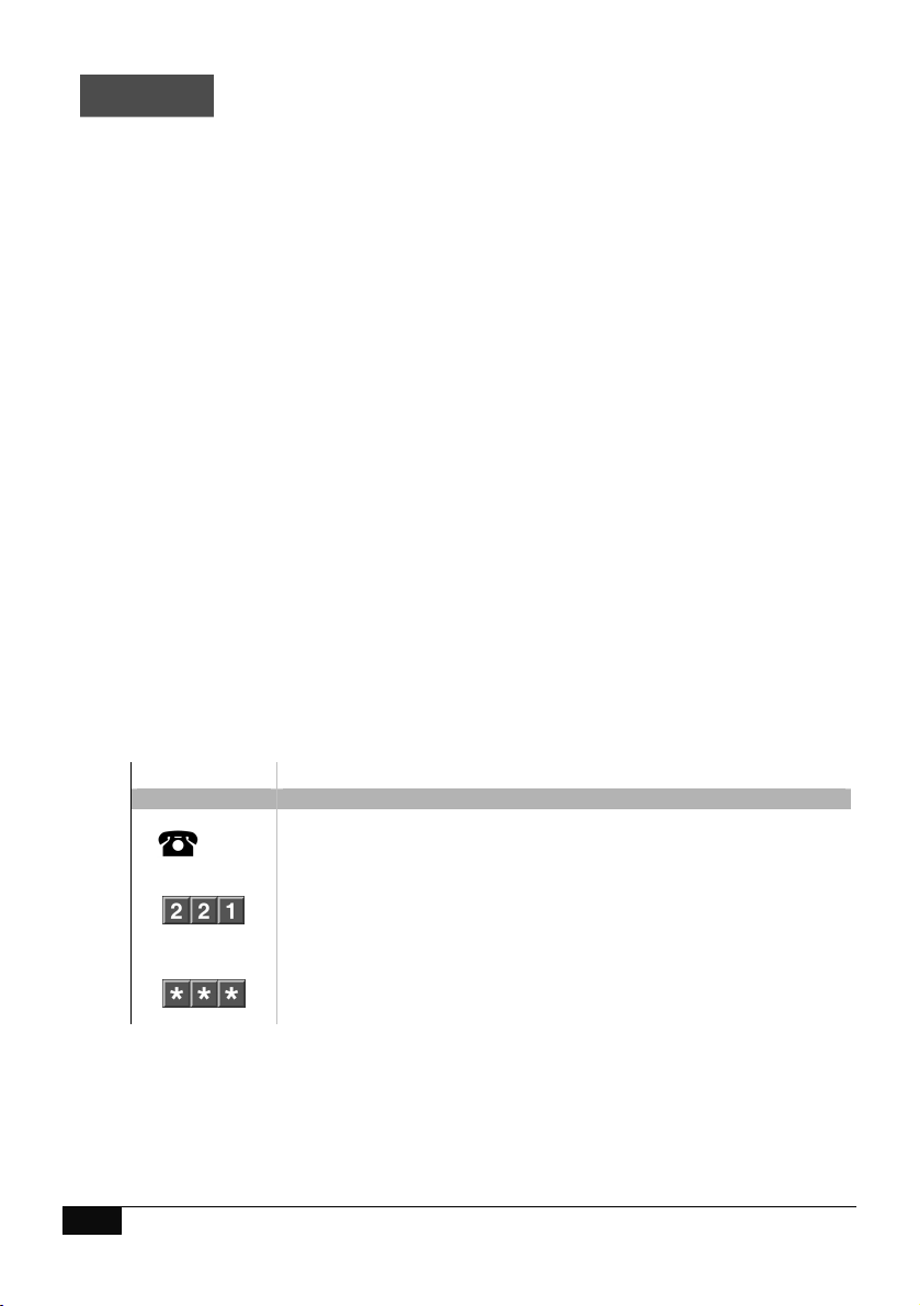
Away Arm – Single area system
How to: Away Arm a single area system
Step Example: Away Arm
1. [PIN] Call the ComNav via an offsite touch-tone phone to begin the session.
2.
Press [2] for system control menu
Press [2] for area control menu
Press [2] two to set in the away mode
3.
1st star, moves back to system control menu
2nd star, moves back to main menu.
3rd star, disconnects session
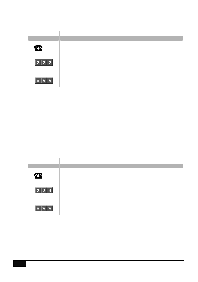
Stay Arm – Single area system
How to: Stay Arm a single area system
Step Example: Stay Arm
1. [PIN] Call the ComNav via an offsite touch-tone phone to begin the session.
2.
Press [2] for system control menu
Press [2] for area control menu
Press [3] to set in the stay mode
3.
1st star, moves back to system control menu
2nd star, moves back to main menu.
3rd star, disconnects session
Table of contents


