hilscher PKV 30-IBS Application guide

Device manual
PKV 30-IBS
Protocol converter for InterBus slave
Hilscher Gesellschaft für Systemautomation mbH
Rheinstraße 78
D-65795 Hattersheim
Germany
Tel. +49 (0) 6190 / 9907 - 0
Fax. +49 (0) 6190 / 9907 - 50
Sales: +49 (0) 6190 / 9907 - 0
Hotline and Support: +49 (0) 6190 / 9907 - 99
e-mail: [email protected]
Homepage: http://www.hilscher.com

Index Date Equipment Equipment-
number Chapter Revision
125.09.97 PKV 30-IBS 9715001 all translated from german manual
329.01.99 PKV 30-IBS 9715001 2.4 revision
Although this appliance has been developed with great care and intensively tested, Hilscher Gesellschaft
für Systemautomation mbH cannot guarantee the suitability of this appliance for any purpose not confir-
med by us in writing.
Guarantee claims shall be limited to the right to require rectification. Liability for any damages which
may have arisen from the use of this appliance or its documentation shall be limited to cases of intent.
We reserve the right to modify our products and their specifiactions at any time in as far as this contribu-
tes to technical progress. The version of the manual supplied with the appliance applies.
Revision 2
Copyright * Hilscher Gesellschaft für Systemautomation mbH * Hotline/Support: +49 (0) 6190/9907-99 * De:P30IBS#3E

1 Introduction ...................................................................................... 4........
1.1 Purpose ....................................................................................... 4........
2 General device description ........................................................................ 5........
2.1 Configuration ................................................................................ 6........
2.1.1 Selection of serial interface type ........................................................ 6........
2.2 Connection of the power supply ............................................................... 7........
2.3 Serial interfaces ............................................................................... 8........
2.3.1 Remote bus interface 'Remote In' ........................................................ 8........
2.3.2 Remote bus interface 'Remote OUT' ..................................................... 9........
2.3.3 Serial device interface ................................................................... 10.......
2.4 Diagnostic interface ........................................................................... 11.......
2.4.1 Activation of the diagnostic/configuration mode ......................................... 12.......
2.5 Status displays - LED ......................................................................... 13.......
2.5.1 Device display .......................................................................... 13.......
2.5.2 InterBus Slave display ................................................................... 14.......
2.6 Physical dimensions ........................................................................... 15.......
3 Technical data ................................................................................... 16.......
Table of contents 3
Copyright * Hilscher Gesellschaft für Systemautomation mbH * Hotline/Support: +49 (0) 6190/9907-99 * De:P30IBS#3E

1 Introduction
1.1 Purpose
There is often a need to transfer data between controllers from different manu-
facturers or exchange them with a higher level host computer. Each system has its
own transfer protocol. Implementation of an alien protocol is often impossible or
only possible at great cost. This results from the following background
conditions:
The interface drivers do not match
The interface controller does not meet the requirements
Insufficient or lacking computer power
Real time requirements cannot be fulfilled
No facility for making additional configuration data available
Missing or insufficient commissioning and diagnosis aids
In some cases, the protocol is only required for a single system. Nevertheless the
implementation has to satisfy extreme quality demands. The effects of a software
error in the transfer protocol can lead to faults ranging up to the standstill of the
entire system and thus cause unpredictable costs.
Experience shows that implementation testing and inspection in particular only
take place in the laboratory or on a system which is hardly capable of
functioning. In spite of the greatest possible care, it then happens that an error on-
ly becomes apparent when the plant is in service. Particularly when the error oc-
curs sporadically or depends on particular plant conditions, location of the error
without an integrated diagnostic function is a matter of luck.
Practical experience shows that most problems are created not by errors in the
implementation but by inadequate agreements on the user level. Message mat-
ching between the linked units is in some cases incomplete or is not complied
with. As a result, messages which have not been sent are expected, or messages
are sometimes mixed up. If the message traffic can be transcribed, the problem
can be rapidly rectified.
The protocol converter is a device developed specifically for these problems,
whose operating system provides all functions necessary for the rational and re-
liable implementation of coupling protocols.
The protocol converter PKV 30-IBS has two communications interfaces and one
of them is for the remote bus InterBus and the other one is for the connection of
the external decive to the PKV 30-IBS. These interface could be also used for
diagnostic.
Introduction 4
Copyright * Hilscher Gesellschaft für Systemautomation mbH * Hotline/Support: +49 (0) 6190/9907-99 * De:P30IBS#3E
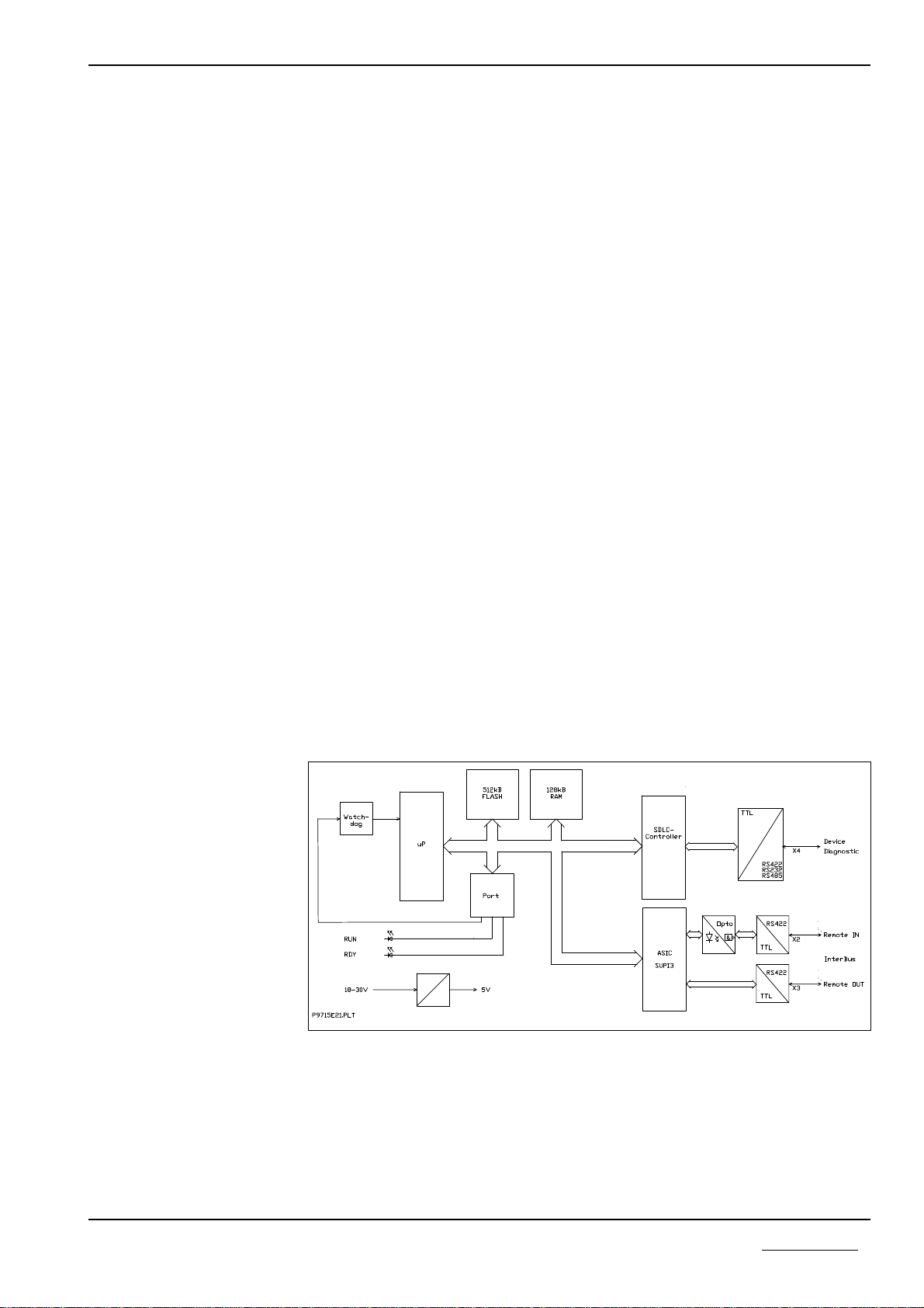
2 General device description
The protocol converter consist of a main board and a power supply board, with
the DC/DC converter which generates all internal voltages.
The main board has a 80C188 microprocessor. It has an internal timer, interrupt-
and DMA controllers and therefore requires only a few external components. The
computing power is sufficient to process even large quantities of data. In additi-
on, the 16-bit processor facilitates efficient software development in a high level
language. The firmware and the configuration data are stored in a FLASH memo-
ry. This can be programmed incircuit and retains its data even when the power
supply is switched off.
The serial interfaces are realized by the SCC controller AM85C30 and the ASIC
SUPI3. For the connection of a device with the converter there is a non-isolated
interface X4 wich can be configured as RS232, RS422 or RS485-type. For the In-
terBus there is one isolated interface X2 (Remote IN) and one non isolated inter-
face X3 (Remote OUT) for the remotebus.
The correct function of the protocol converter and its internal power supply are
monitored by a watchdog circuit with the MAX 705 component. In the case of er-
ror, this triggers a reset on the processor.
The internal power supply is provided by a switching controller. Its input voltage
is filtered through a current compensated annular core reactor and filter capaci-
tors. A transient diode is provided as overvoltage and reverse polarity protection.
In the case of a fault, the internal semiconductor fuse switch off until the fault
disappears. In addition, there is a charging capacitor which blocks voltage drops
such as those which occur on switching of contactors.
Valid operation and an error state from the serial interfaces are displayed by
LEDs.
Block diagram of the protocol converter PKV 30-IBS
General device description 5
Copyright * Hilscher Gesellschaft für Systemautomation mbH * Hotline/Support: +49 (0) 6190/9907-99 * De:P30IBS#3E

2.1 Configuration
2.1.1 Selection of serial interface type
The hardware of the converter has jumper J2, to switch between the different
types of serial interfaces. This jumper is accessable if you open the side plate on
the side with connector X1 and X4. This is be done by removing four screws. The
following picture will show the position of the jumper seeing from the side of the
converter. With the help of the table you can chose the right type of interface.
selection jumper J2 interface
open RS232
3-4 RS485
1-2, 3-4 RS422
Selection of serial interface type
connector COMBICON connector male
14 3 2
jumper row
Side viewing of PKV 30-IBS with jumper row
X1 X4
14 3 2
General device description 6
Copyright * Hilscher Gesellschaft für Systemautomation mbH * Hotline/Support: +49 (0) 6190/9907-99 * De:P30IBS#3E

2.2 Connection of the power supply
The protocol converter requires a 24V power supply. For the maximum current
look abaut chapter 'Technical data'. A three-phase rectifier or simple rectifier
circuit with charging capacitor are sufficient. The power supply must be earth
grounded. The power supply is connected over the plug-in screw terminal X1. A
3-way COMBICON plug from PHOENIX (MSTB 2.5/3-ST-5.08) is used.
pin symbol signal
1+24V +24V supply voltage
20V reference potential
3PE earth ground
Pin assignment of the X1 power supply connector
General device description 7
Copyright * Hilscher Gesellschaft für Systemautomation mbH * Hotline/Support: +49 (0) 6190/9907-99 * De:P30IBS#3E

2.3 Serial interfaces
The PKV 30-IBS has two independent serial interfaces. The first interface can be
used for diagnostic or to connect with an other device. It is configurable with
jumpers as RS232, RS422, or RS485-interface. The second interface is the con-
nection for the InterBus remmote bus network.
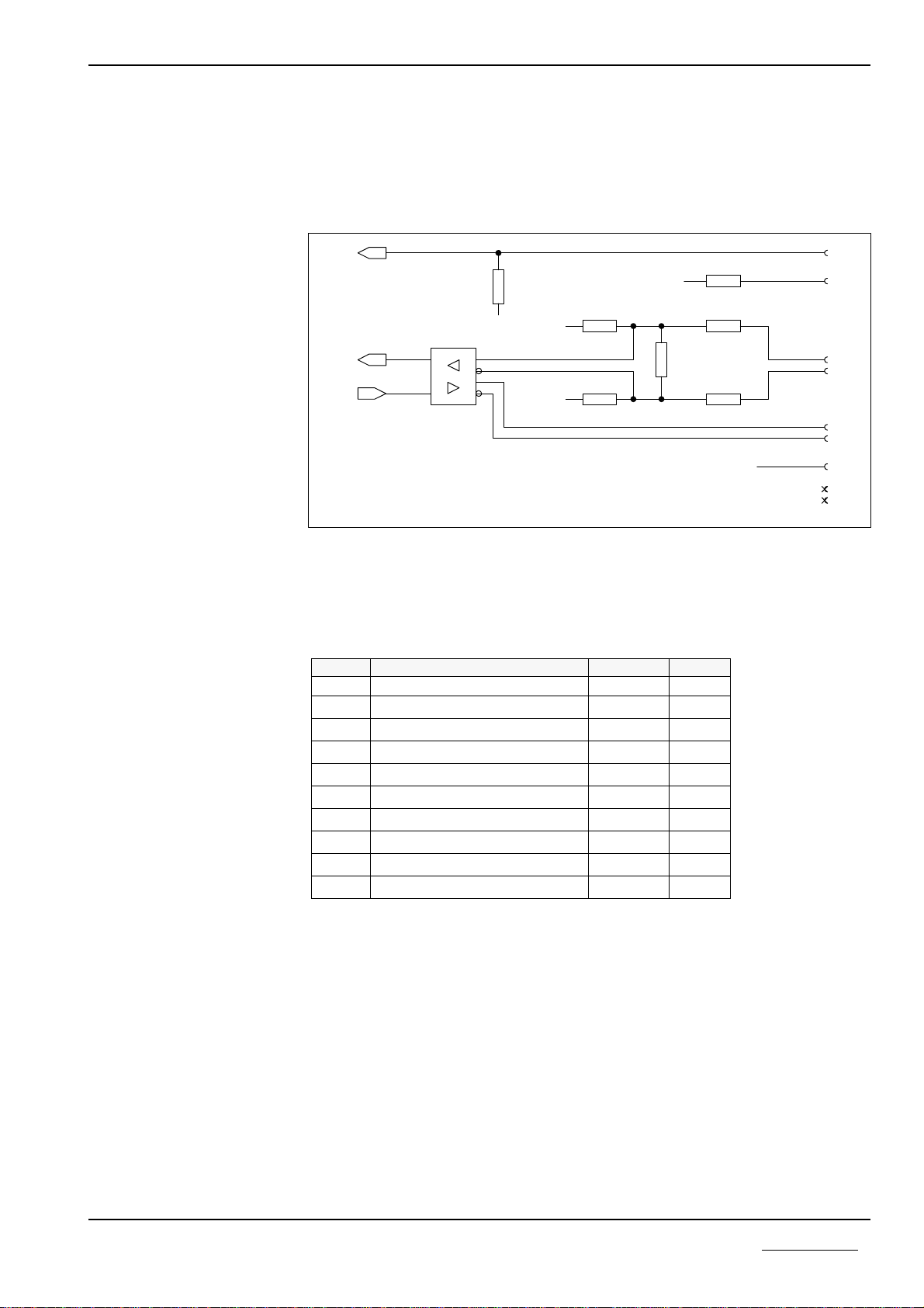
2.3.1 Remote bus interface 'Remote In'
The complete interface circuit of the InterBus is integrated at the PKV 30-IBS.
The buscable from master or the last slaves will be connected to these 9 way D-
Sub male connector with pinout in accordance with the InterBus standard. There
is no configuration necessary.
Circuit of the 'Remote IN' interface at connector X2 of PKV 30-IBS
The shield of the connector is connected to the earth ground of the PKV 30-IBS
over a RC combination (1 MOhm, 15 nF).
Pin Signal Symbol Type
1receive data line + DO2 RS485
2transmit data line + DI2 RS485
3iso. 0V voltage supply ISOGND
4not connected NC
5not connected NC
6receive data line - DO2¯¯¯¯ RS485
7 transmit data line - DI2¯¯¯ RS485
8 not connected NC
9not connected NC
shield over RC combination to earth ground of PKV 30-IBS
Pinning of the 'Remote IN' interface at connector X2 at the PKV 30-IBS
6
7
4
5
1
2
3
7
6
2
3
7
6
2
3
8
7
5
6
8
9
3
2
X2
X2
X2
X2
X2
C13A
R12 R8
&
U2R20
&
U1
N1
R19
R18
X2
X2
X2
X2
R13
R15
R17
R14
R16
R
Y
ZD
A
B
15n/630V
390 1M
HCPL0601
390
HCPL0601
75179D
390
390
220
100
220
15
15
12
1 2
12
1
2
1 2
1
2
1 2 1
2
1 2
1 2
1 2
ISO+5V ISO+5V
ISO+5V
ISOGND
ISOGND
RX1
PE2
+5V
+5V
TX1
PE
P9715S21.HP
General device description 8
Copyright * Hilscher Gesellschaft für Systemautomation mbH * Hotline/Support: +49 (0) 6190/9907-99 * De:P30IBS#3E
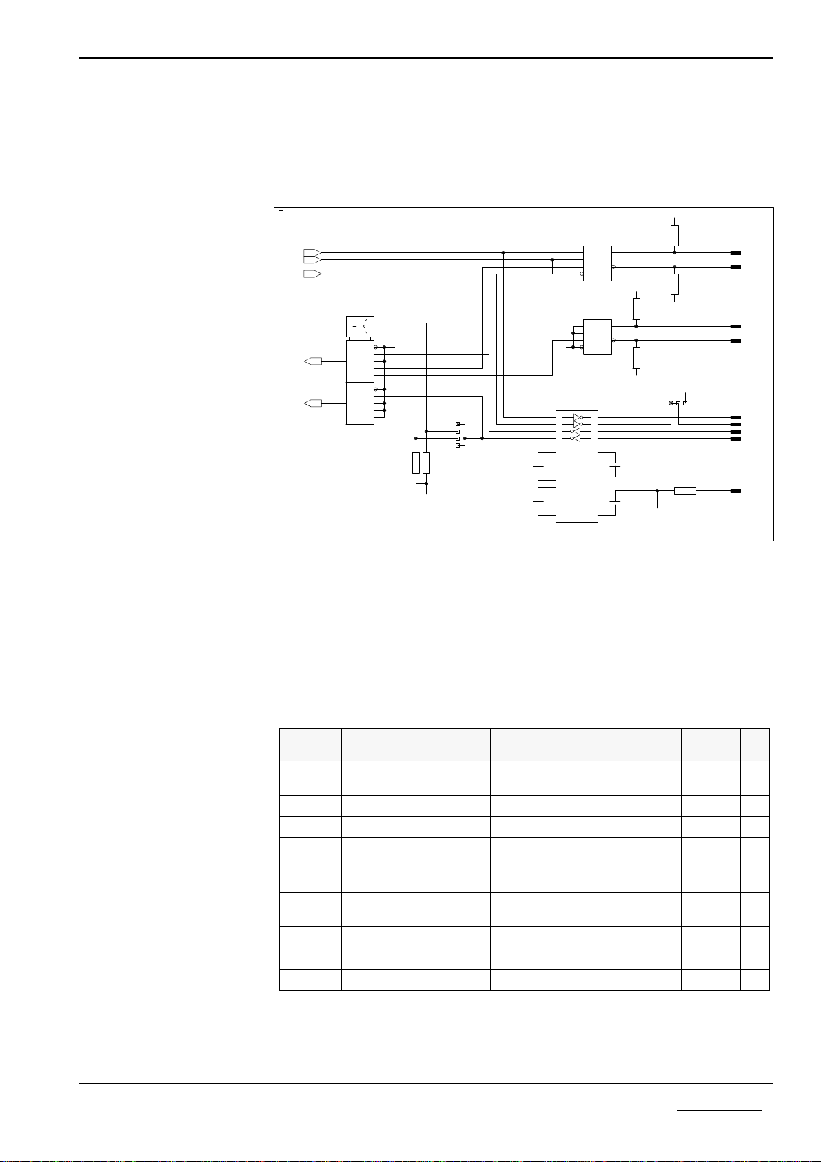
2.3.2 Remote bus interface 'Remote OUT'
The PKV 30-IBS has these fieldbus interface connection to connect the bus cable
to the next slave. A 9 way D-Sub female connector is used. The next picture
shows the scematic of the interface. The interface is not isolated by optocouplers
Circuit of the 'Remote OUT' interface at connector X3 of the PKV 30-IBS'
The shield of the connector is directly connected to earth ground of the PKV
30-IBS.
Pin Signal Symbol Type
1transmit data line + DO2 RS485
2receive data line + DI2 RS485
3iso. 0V voltage supply ISOGND
4not connected NC
5iso. 5V voltage supply ISO+5V
6transmit data line - DO2¯¯¯¯ RS485
7 receive data line - DI2¯¯¯ RS485
8 not connected NC
9bus connector in BC
Shield earth potential, cardholder PE
Pinning of the 'Remote OUT' interface at connector X3
9
1
2
3
4
5
6
7
8
2
3
8
7
5
6
X3
X3
R22
X3
X3
X3
X3
X3
X3
X3
R25
R23
R26
N2
R27
R28
R24
R
Y
ZD
A
B
100
2.7k
220
220
75179D
100
15
15
1 2
1
2
1 2
1 2 1
2
1 2
1 2
TX2
+5V
+5V
RX2
GND
GND
GND
BC
P9715S31.HP
General device description 9
Copyright * Hilscher Gesellschaft für Systemautomation mbH * Hotline/Support: +49 (0) 6190/9907-99 * De:P30IBS#3E
2.3.3 Serial device interface
These serial interface uses a 9 way D-Sub connector for the connection to an ex-
ternal device with an serial RS232, RS422, or RS485-interfaces. The interface is
configurable.
Output scematic of the serial device interface at connector X4
The resistors R33, R34 and R35, R37 are necessary to get a defined potential on
the RS485/RS422-bus if there is no active transmitter or the connector is left
open. All resistance have a value of 10 kOhm.
The following table describes the signals of the different kind of interfaces. It is
not allowed to make any connections to the other signals of the not used kind of
interfaces.
pin input/
output signal
name signal RS
485 RS
422 RS
232
1input/
output RXD/TXD-N transmit data inverted RS 422
data inverted RS485 ü ü
2input RXD receive data RS 232 ü
3output TXD transmit data RS 232 ü
4input RXD-P receive data RS 422 ü
5RGND reference potential accros
100 Ohm ü ü ü
6input/
output RXD/TXD-P transmit data RS 422
data RS 485 ü ü
7output RTS ready to send ü
8input CTS clear to send ü
9input RXD-N receive data inverted RS 422 ü
Pin assignment of the serial device interface X4
11
10
12
9
1
3
4
5
14
7
13
8
2
6
8
2
9
5
4
3
1
2
6
7
4
3
1
2
6
7
7
14
2
1
6
5
4
3
15
10
11
12
13
7
9
3
6
1
4
1
2
3
4
D17
X4
X4
X4
X4
C29
N3
R37
N4
R39
X4
D10
C31
C28
C30
R33
X4
J3
R38
X4
X4
X4
J2
R34
R35
R40
C1+
C1-
C2+
C2-
V+
V-
D
DE
R
RE
A
B
D
DE
R
RE
A
B
MUX
Y
Y
3
2
1
0
EN
3
2
1
0
EN
3
0G1
0
MAX202
74HCT153
100n
ADM485JR
10k
ADM485JR
10k 100n
100n
100n
10k
100
10k
10k
10k
1
2
1
2
1
2
1
2
1
2
1
2
1
2
1 2 3
1 2
1
2
1
2
1
2
GND
GND GND
GND
GND
GND
TXD
RX/TXDB
RX/TXDA
EN422
EN485
+5V
+5V
+5V
+5V
RXDB
CTS
CTS
RTS
RTS
TX
RTS22
RGND
RXDA
RX
RXD
P9715S11.HP
General device description 10
Copyright * Hilscher Gesellschaft für Systemautomation mbH * Hotline/Support: +49 (0) 6190/9907-99 * De:P30IBS#3E
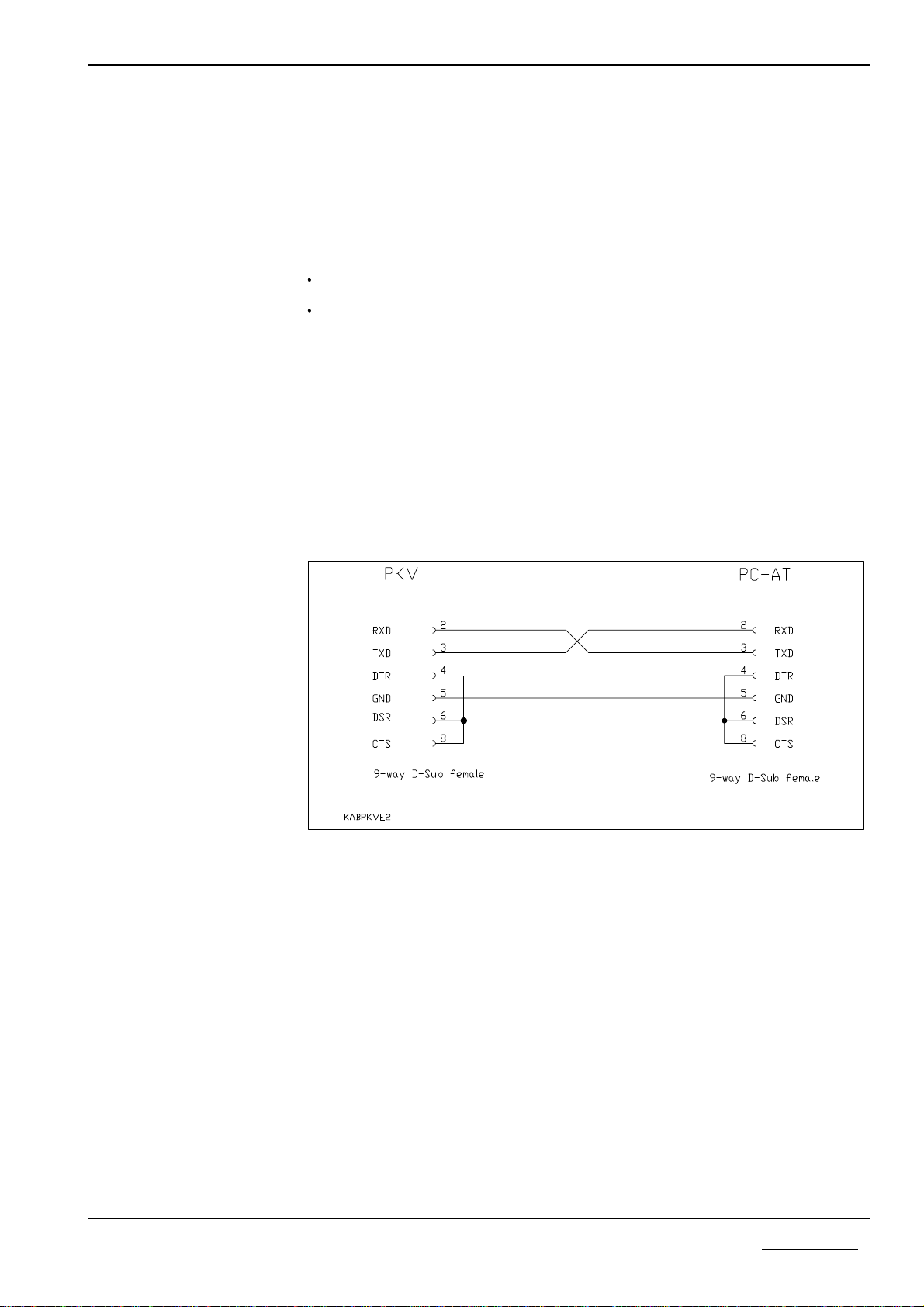
2.4 Diagnostic interface
This interface at connector X4 facilitates the connection of a PC to the protocol
converter. It conforms to the RS232C standard to CCITT or DIN. Only the
necessary signals are provided.
The control signals are produced and evaluated as follows:
RTS is switched to high on readiness for operation and not changed.
CTS must be connected internal with Pin 4 and 8 of D-Sub connector
A 9-way D-Sub connector to DIN 41652 is used.
Data transfer between the PC and the protocol converter takes place at 9600 Baud
and uses the following data format: 8 data bits, 1 stop bit and even parity. The
3964R protocol is used as the transfer protocol.
The PC is connected by a three-way cable which must not be longer than 15 m.
The wiring of the cable is shown below.
Diagnostic cable between the protocol converter and the PC
General device description 11
Copyright * Hilscher Gesellschaft für Systemautomation mbH * Hotline/Support: +49 (0) 6190/9907-99 * De:P30IBS#3E

The interface on connector X3 of the PKV 30-IBS is designed for
communication
respectively for
diagnostic/configuration
If the power of the protocol converter is switched on, it checks the serial interface
if the diagnostic/configuration mode should be activated, otherwise it starts the
communication mode.
2.4.1 Activation of the diagnostic/configuration mode
Connect the diagnostic cable on X3 of the protocol converter and to COM1 (or
COM2) of the PC.
Start the program ComPro
COMPRO /S:1 respectively. COMPRO /S:2
(for COM1 respectively COM2).
Select menu online - system - bootstart. A windows appears that shows The sy-
stem will be reseted and the bootloader becomes active without starting any
firmware.
Turn off power of the protocol converter and wait at least 10 seconds.
Accept the message The system will be reseted and the bootloader becomes acti-
ve without starting any firmware with press the Enter key. A red window appears
that shows Waiting for hardware receipt.
Power on the protocol converter.
The red window disappears.
To test if the protocol converter is in diagnostic/configuration mode select menu
online system - firmware. If a window appears and shows the name of the firm-
ware, then the diagnostic/configuration mode is active. If the message Connection
could not be established or connection lost appears, then try to activate the dia-
gnostic/configuration mode again according to the steps described above.
General device description 12
Copyright * Hilscher Gesellschaft für Systemautomation mbH * Hotline/Support: +49 (0) 6190/9907-99 * De:P30IBS#3E
2.5 Status displays - LED
On the PKV 30-IBS there are two groups of state LEDs. One group displays the
state of the PKV 30-IBS device and the other group shows the state of the Inter-
Bus slave.
2.5.1 Device display
Display Colour State Meaning
If the device is defective, it is pos-
sible that the watchdog responds
cyclically, what results also in a
cyclically flashing of the
RDY-LED.
RDY yellow on
flashing cyclic
flashing non cyclic
off
PKV ready
bootstrap loader active
hardware or system error
hardware error
RUN green on
flashing non cyclic (see below)
off
communication running
parameter error
no communication
ERR red on error on communication interface to
external device
When switched on, the PKV performs a self-test. If this is performed without er-
ror, the yellow RDY LED is switched on. Otherwise, the LED starts to flash, and
further running of the program is aborted.
If no firmware has been loaded in the PKV, the bootstraploader displays this by
regular flashing of the RDY LED at one second intervals. The flash frequency is
increased to approx. 5 Hz while the firmware is being loaded.
Stays the LED off the may be a defect.
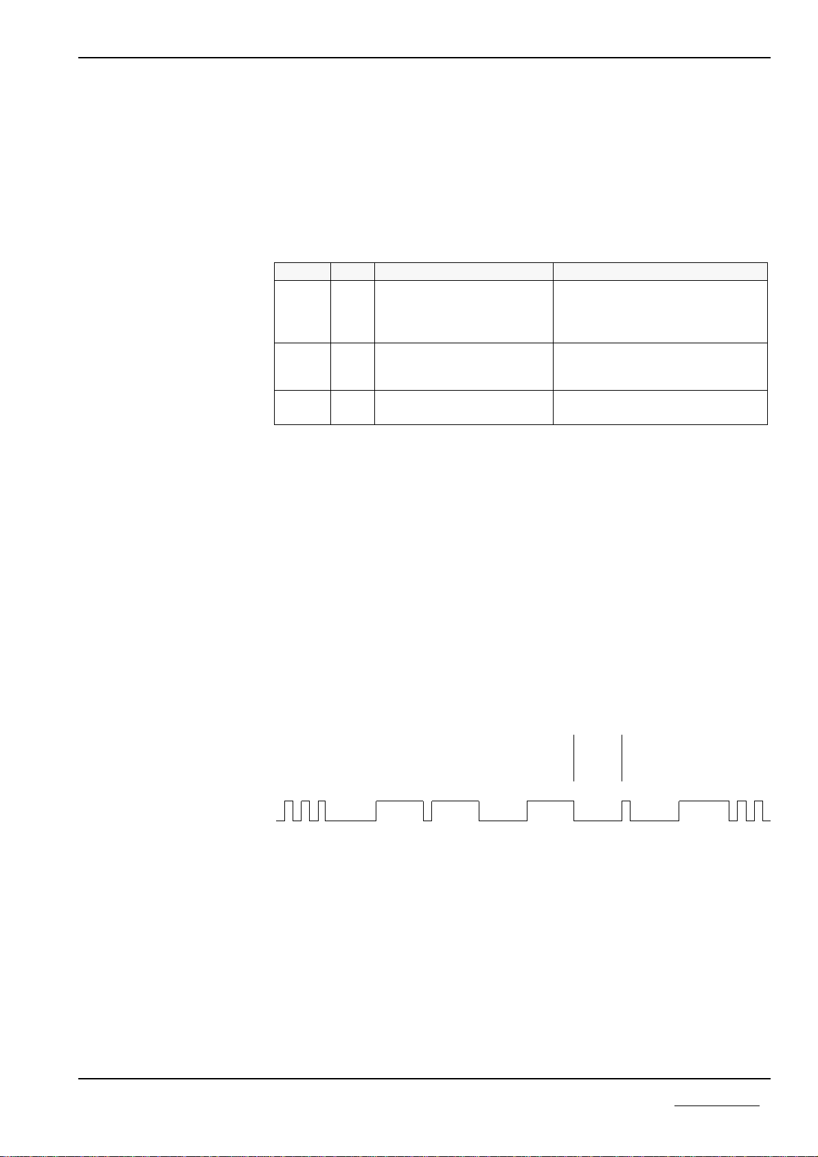
If a parameterization error is detected by a protocol task, the task is displayed by
the RUN LED as shown in the illustration below.
If no error occurs and communication has started, the RUN LED is switched on.
Is this LED blinking cyclic, no parameterization error has been detected, but the
communication on the bus has not been established.
If communication is blocked, e.g. by the 'System start' parameter, the RUN LED
remains off.
Start
detec-
tion
Data bits with separation
detection -> 1 sec. <- Start
again
Display by the LED is from left to
right
RCS
with
DBM
error
Task 1
without
error
Task 2
without
error
Task 3
with
error
Task 4
without
error
Task 5
with
error
Task 6
with
error
Task 7
not
implem-
ented
Display of the task which reports a parameterization error
The red LED ERR displays data transfer errors at the communications interface
to the connected devide.
General device description 13
Copyright * Hilscher Gesellschaft für Systemautomation mbH * Hotline/Support: +49 (0) 6190/9907-99 * De:P30IBS#3E

2.5.2 InterBus Slave display
For diagnostic of the InterBus slave and the InterBus there are five state LEDs at
the PKV 30-IBS
Display Colour State Meaning
ULgreen on
off internal 5V power good
internal 5V power fault
RC yellow on
off remote bus check ok
no connection to previous slave or master
BA green on
off data telgramms over InterBus active
no data telegramms over InterBus active
RD red on
off interface 'Remote bus OUT' disabled
interface 'Remote bus OUT' enabled
TR green on
off PCP data telegramms active
no PCP data telegramms active
Meaning of the different state LEDs of the PKV 30-IBS
General device description 14
Copyright * Hilscher Gesellschaft für Systemautomation mbH * Hotline/Support: +49 (0) 6190/9907-99 * De:P30IBS#3E
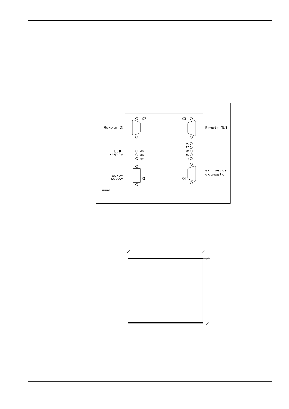
2.6 Physical dimensions
The protocol converter is installed in an aluminium enclosure. This facilitates di-
rect installation in the cabinet on a mounting rail (TS35 to DIN EN 50022). As an
alternative, an enclosure variant for direct screw fitting on an assembly wall is
available.
The physical dimensions and the arrangement of the plug connectors are shown
in the drawings below.
Connector arrangement on the protocol converter
Physical dimensions of the protocol converter for snap mounting to a mounting
rail
The overall height of the converter is approx. 80 mm.
105
105
General device description 15
Copyright * Hilscher Gesellschaft für Systemautomation mbH * Hotline/Support: +49 (0) 6190/9907-99 * De:P30IBS#3E

3 Technical data
Processor 16 Bit with timer, interrupt- and DMA-controller
Memory range 128 kByte RAM, 512 kByte FLASH
Serial interface X4 configurable as non isolated RS232C, RS422,
RS485-interface, max. data transmission 19.2 kBaud,
asynchronous, synchronous,
NRZ, NRZ, SDLC, HDLC,
also used as diagnostic interface
InterBus interface 2 way remote bus, 'Remote IN' interface isolated, 'Re-
mote OUT' not isolated, data transmission 500 kBaud
InterBus input data max. 10 words
InterBus output data max 10 words
InterBus protocoll process data channel, PCP channel, data width freely
chooseable
Display-LEDs system running and communication running of PKV
30-IBS, communication error on serial interface, Inter-
Bus controll LEDs UL, RC, BA, RD, TR
Operating voltages 18V - 30V, max. 0.15 A at 24 V
Operating temperature 0 to 50 degrees Celsius
Safety type IP50
Dimensions (LxHxD) 105 x 105 x 80 mm
Mounting rail mounting DIN EN 50022
Technical data 16
Copyright * Hilscher Gesellschaft für Systemautomation mbH * Hotline/Support: +49 (0) 6190/9907-99 * De:P30IBS#3E
Table of contents
Other hilscher Media Converter manuals


