Zapi CAN TILLER User manual

ELECTRONIC • OLEODYNAMIC • INDUSTRIAL
EQUIPMENTS CONSTRUCTION
Via Parma, 59 – 42028 – POVIGLIO (RE) – ITALY
Tel +39 0522 960050 (r.a.) – Fax +39 0522 960259
EN
User Manual
CAN TILLER

Page - 2/18 ADBZP0AB - CAN TILLER - User Manual
Copyright © 1975-2009 Zapi S.p.A.
All rights reserved
The contents of this publication is a ZAPI S.p.A. property; all related authorizations are covered
by Copyright. Any partial or total reproduction is prohibited.
Under no circumstances will Zapi S.p.A. be held responsible to third parties for damage caused
by the improper use of the present publication and of the device/devices described in it.
Zapi spa reserves the right to make changes or improvements to its products at any time and
without notice.
The present publication reflects the characteristics of the product described at the moment of
distribution. The publication therefore does not reflect any changes in the characteristics of the
product as a result of updating.
is a registered trademark property of Zapi S.p.A.
NOTES LEGEND
4The symbol aboard is used inside this publication to indicate an annotation or a
suggestion you should pay attention.
UThe symbol aboard is used inside this publication to indicate an action or a
characteristic very important as for security. Pay special attention to the
annotations pointed out with this symbol.

ADBZP0AB - CAN TILLER - User Manual Page - 3/18
Contents
1MAIN FEATURES .................................................................................................................4
2TECHNICAL SPECIFICATION .............................................................................................5
2.1 Digital inputs...............................................................................................................5
2.1.1 Digital inputs technical details.......................................................................5
2.1.2 Microswitches ...............................................................................................5
2.2 Analog inputs..............................................................................................................5
3INSTALLATION HINTS.........................................................................................................7
3.1 Material overview........................................................................................................7
3.1.1 Connection cables ........................................................................................7
3.1.2 Fuses............................................................................................................7
3.2 Installation of the hardware.........................................................................................7
3.2.1 Wirings: CAN connections and possible interferences.................................8
3.2.2 Wirings: I/O connections.............................................................................10
3.2.3 Insulation of truck frame..............................................................................10
3.3 Protection and safety features..................................................................................10
3.3.1 Protection features......................................................................................10
3.3.2 Safety Features...........................................................................................10
3.4 EMC..........................................................................................................................11
4DESCRIPTION OF THE CONNECTORS............................................................................13
4.1 A connector: Molex Minifit, 16 pins...........................................................................13
4.2 B connector: Molex Minifit, 6 pins.............................................................................13
4.3 C connector: Molex Minifit, 8 pins.............................................................................13
5DRAWINGS.........................................................................................................................14
5.1 Mechanical drawing..................................................................................................14
5.2 Functional drawing....................................................................................................16
6RECOMMENDED SPARE PARTS .....................................................................................17
7PERIODIC MAINTENANCE TO BE REPEATED AT TIMES INDICATED.........................18
APPROVAL SIGNS
COMPANY FUNCTION INITIALS SIGN
PROJECT MANAGER FG
TECHNICAL ELECTRONIC
MANAGER VISA PP
SALES MANAGER VISA MC
Publication N°: ADBZP0AB
Edition: March 2009

Page - 4/18 ADBZP0AB - CAN TILLER - User Manual
1 MAIN FEATURES
The function of the Can Tiller board is acquiring analog and digital inputs and
sending them to other Can network’s nodes via Can Bus.
Twelve digital inputs at 24 V/12 V
Four analog inputs with potentiometer’s output in the 0-5 V range or 0-12 V range
Two inputs which can be used as analog or digital inputs (CNC#7 and CNC#8)
Supply Voltage:.......................................................................................24 V/ 12 V
External temperature working range:................................................-30 °C ÷ 80 °C
CAN interface [n°]..................................................................................................1

ADBZP0AB - CAN TILLER - User Manual Page - 5/18
2 TECHNICAL SPECIFICATION
2.1 Digital inputs
All the digital inputs have the positive input at Key voltage (+12 V or +24 V).
Proper microswitches must be connected between the digital input and the
positive supply output CMM (CNA#15); each input has a pull-down resistor.
The FW, REV, RAISE, LOS, HORN, ETC microswitches are typically open, so
the functions related to them become active when the microswitch is closed.
The safety microswitches, as SR, are typically closed, so the functions related to
them become active when the microswitch is open.
2.1.1 Digital inputs technical details
DI1 ÷ DI2
- Commutation threshold ON to OFF: 7 V [±0,5 V].
- Commutation threshold OFF to ON: 9 V [±0,5 V].
- Input impedance: 4,3 kohm [±0,5 kohm].
DI3 ÷ DI11 and DI14
- Commutation threshold: 6 V [±0,5 V].
- Input impedance: 4,25 kohm [±0,3 kohm].
- Input impedance: 7,4 kohm [±0,4 kohm] only for DI4 and DI5.
DI12/AI5
- Commutation threshold: 5 V [±0,5 V].
- Input impedance: 47,3 kohm [±2,4 kohm].
DI13/AI6
- Commutation threshold ON to OFF: 3,2 V [±0,3 V].
- Commutation threshold OFF to ON: 7,5 V [±0,5 V].
- Input impedance: 47,3 kohm [±2,4 kohm].
4NOTE: DI12 AND DI13 can be used as Analog Input, as well see 2.2.
2.1.2 Microswitches
- The recommended microswitches must have a contact resistance lower than
0.1 Ωand a leakage current lower than 100 µA.
- When full load connected, the voltage between the key switch contacts must
be lower than 0.1 V.
- If the used microswitches have different features, it is recommended to talk
about their utilization with Zapi’s technicians.
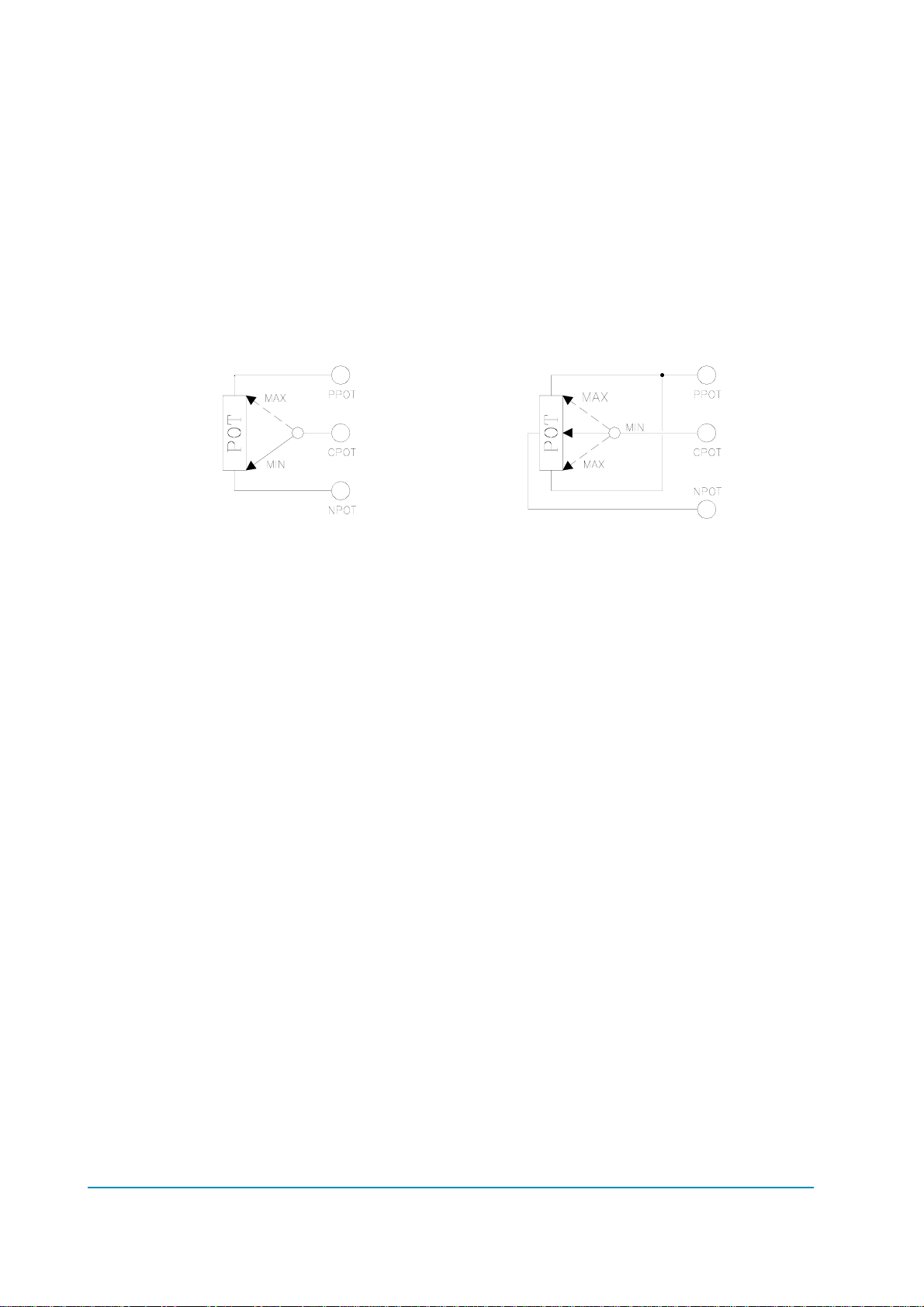
2.2 Analog inputs
The analog inputs are used to read the output of a potentiometer or an Hall effect
device, both with output continuously variable in the 0-5 V range or in the 0-12 V
range.
The potentiometer can be in a 3-wire configuration. The potentiometers related to

Page - 6/18 ADBZP0AB - CAN TILLER - User Manual
the AI1 and AI2 analog inputs take the power supply between PPOT (CNA#9)
and NPOT (CNC#3). The potentiometers related to the AI3 and AI4 analog inputs
take the power supply between PPOT (CNA#9) and NPOT (CNA#12).
The analog devices converted to AI5 and AI6 take the power supply between
PPOT (CAN#9) and NPOT (CAN#12).
The potentiometer supply available are +12 V or +5 V; the maximum load current
provided by the internal voltage regulator is 100 mA so the minimum load is 47 Ω
(PPOT=+5 V), 120 Ω(PPOT=+12 V).
The standard connection of a potentiometer is represented on the left of the
picture below (the potentiometer is at rest in an extreme), together a pair of
switches for the running request. It is possible to use the configuration on the
right (the potentiometer is at rest in the centre), together a pair of switches for the
running request too.

ADBZP0AB - CAN TILLER - User Manual Page - 7/18
3 INSTALLATION HINTS
In the description of these installation suggestions you will find some boxes of
different colours, they mean:
4These are information useful for anyone is working on the installation, or a
deeper examination of the content
UThese are Warning boxes, they describe:
- operations that can lead to a failure of the electronic device or can be
dangerous or harmful for the operator;
- items which are important to guarantee system performance and safety
3.1 Material overview
Before to start it is necessary to have the required material for a correct
installation. Otherwise a wrong choice of cables or other parts could lead to
failures/ misbehaviour/ bad performances.
3.1.1 Connection cables
For the auxiliary connections, use cables of 0.5 mm² section.
3.1.2 Fuses
- Use a 10 A Fuse for protection of the card.
- For Safety reasons, we recommend the use of protected fuses in order to
prevent the spread of fused particles should the fuse blow.
3.2 Installation of the hardware
UBefore doing any operation, ensure that the battery is disconnected and
when all the installation is completed start the machine with the drive
wheels raised from the floor to ensure that any installation error do not
compromise safety.
Do not connect the card to a battery with a nominal voltage different than
the value indicated on the label. A higher battery voltage may cause a logic
failure. A lower voltage may prevent the logic operating.

Page - 8/18 ADBZP0AB - CAN TILLER - User Manual
3.2.1 Wirings: CAN connections and possible interferences
4CAN stands for Controller Area Network. It is a communication protocol for real
time control applications. CAN operates at data rate of up to 1 Megabits per
second.
It was invented by the German company Bosch to be used in the car industry to
permit communication among the various electronic modules of a vehicle,
connected as illustrated in this image:
- The best cable for can connections is the twisted pair; if it is necessary to
increase the immunity of the system to disturbances, a good choice would
be to use a cable with a shield connected to the frame of the truck.
Sometimes it is sufficient a simple double wire cable or a duplex cable not
shielded.
- In a system like an industrial truck, where power cables carry hundreds of
Ampere, there are voltage drops due to the impedance of the cables, and
that could cause errors on the data transmitted through the can wires. In the
following figures there is an overview of wrong and right layouts of the cables
routing.
UWrong Layout:
The red lines are can wires.
The black boxes are different modules, for example traction controller, pump
controller and display connected by canbus.
The black lines are the power cables.
Module
1
Module
3
Module
2
R
R
Can Bus
Power cables

ADBZP0AB - CAN TILLER - User Manual Page - 9/18
This is apparently a good layout, but can bring to errors in the can line.
The best solution depends on the type of nodes (modules) connected in the
network.
If the modules are very different in terms of power, then the preferable
connection is the daisy chain.
UCorrect Layout:
Note: Module 1 power > Module 2 power > Module 3 power
The chain starts from the –BATT post of the controller that works with the
highest current, and the others are connected in a decreasing order of power.
Otherwise, if two controllers are similar in power (for example a traction and a
pump motor controller) and a third module works with less current, the best way
to deal this configuration is to create a common ground point (star configuration).
UCorrect Layout:
Note: Module 1 power
≈
Module 2 power > Module 3 power
In this case the power cables starting from the two similar controllers must be as
short as possible. Of course also the diameter of the cable concurs in the voltage
drops described before (higher diameter means lower impedance), so in this last
example the cable between the minus of the Battery and the common ground
point (pointed by the arrow in the image) must be dimensioned taking into
account thermal and voltage drop problems.
Module
1Module
2
Module
3
R
R
Can Bus
Power cables
Center of the Ground connection
Module
1Module
2
Module
3
R
R
Can Bus
Power cables

Page - 10/18 ADBZP0AB - CAN TILLER - User Manual
4Can advantages
The complexity of today systems needs more and more data, signal and
information must flow from a node to another. CAN is the solution to different
problems that arise from this complexity
- simplified design (readily available, multi sourced components and tools)
- lower costs (less and smaller cables )
- improved reliability (fewer connections)
- analysis of problems improved (easy connection with a pc to read the data
flowing through the cable).
3.2.2 Wirings: I/O connections
- After crimping the cable, verify that all strands are entrapped in the wire
barrel.
- Verify that all the crimped contacts are completely inserted on the connector
cavities.
UA cable connected to the wrong pin can lead to short circuits and failure;
so, before turning on the truck for the first time, verify with a multimeter the
continuity between the starting point and the end of a signal wire.
- For information about the mating connector pin assignment see the
paragraph “description of the connectors”.
3.2.3 Insulation of truck frame
UAs stated by EN-1175 “Safety of machinery – Industrial truck”, chapter 5.7,
“there shall be no electrical connection to the truck frame”. So the truck
frame has to be isolated from any electrical potential of the truck power
line.
3.3 Protection and safety features
3.3.1 Protection features
- Connection Errors:
All inputs are protected against connection errors.
- External agents:
The controller is protected against dust and the spray of liquid to a degree of
protection meeting IP54.
3.3.2 Safety Features
UZAPI devices are designed according to the prEN954-1 specifications for
safety related parts of control system and to UNI EN1175-1 norm.
The safety of the machine is strongly related to installation; length, layout
and screening of electrical connections have to be carefully designed.
ZAPI is always available to cooperate with the customer in order to evaluate

ADBZP0AB - CAN TILLER - User Manual Page - 11/18
installation and connection solutions. Furthermore, ZAPI is available to
develop new SW or HW solutions to improve the safety of the machine,
according to customer requirements.
Machine manufacturer holds the responsibility for the truck safety features
and related approval.
3.4 EMC
UEMC and ESD performances of an electronic system are strongly
influenced by the installation. Special attention must be given to the
lengths and the paths of the electric connections and the shields. This
situation is beyond ZAPI's control. Zapi can offer assistance and
suggestions, based on its years experience, on EMC related items.
However, ZAPI declines any responsibility for non-compliance,
malfunctions and failures, if correct testing is not made. The machine
manufacturer holds the responsability to carry out machine validation,
based on existing norms (EN12895 for industrial truck; EN50081-2 for other
applications).
EMC stands for Electromagnetic Compatibility, and it represents the studies and
the tests on the electromagnetic energy generated or received by an electrical
device.
So the analysis works in two directions:
1) The study of the emission problems, the disturbances generated by the
device and the possible countermeasure to prevent the propagation of that
energy; we talk about “conduction” issues when guiding structures such as
wires and cables are involved, “radiated emissions” issues when it is studied
the propagation of electromagnetic energy through the open space. In our
case the origin of the disturbances can be found inside the controller with the
switching of the mosfets which are working at high frequency and generate
RF energy, but wires and cables have the key role to propagate the
disturbs because they works as antennas, so a good layout of the cables
and their shielding can solve the majority of the emission problems.
2) The study of the immunity can be divided in two main branches: protection
from electromagnetic fields and from electrostatic discharge.
The electromagnetic immunity concern the susceptibility of the controller
with regard to electromagnetic fields and their influence on the correct work
made by the electronic device.
There are well defined tests which the machine has to be exposed to.
These tests are carried out at determined levels of electromagnetic fields, to
simulate external undesired disturbances and verify the electronic devices
response.
3) The second type of immunity, ESD, concerns the prevention of the effects of
electric current due to excessive electric charge stored in an object. In fact,
when a charge is created on a material and it remains there, it becomes an
“electrostatic charge”; ESD happens when there is a rapid transfer from a

Page - 12/18 ADBZP0AB - CAN TILLER - User Manual
charged object to another. This rapid transfer has, in turn, two important
effects:
A) this rapid charge transfer can determine, by induction, disturbs on the
signal wiring and thus create malfunctions; this effect is particularly
critical in modern machines, with serial communications (canbus)
which are spread everywhere on the truck and which carry critical
information.
B) in the worst case and when the amount of charge is very high, the
discharge process can determine failures in the electronic devices; the
type of failure can vary from an intermittently malfunction to a completely
failure of the electronic device.
UIMPORTANT NOTE: it is always much easier and cheaper to avoid ESD
from being generated, than to increase the level of immunity of the
electronic devices.
There are different solutions for EMC issues, depending on level of emissions/
immunity required, the type of controller, materials and position of the wires and
electronic components.
1) EMISSIONS. Three ways can be followed to reduce the emissions:
A) SOURCE OF EMISSIONS: finding the main source of disturb and work
on it.
B) SHIELDING: enclosing contactor and controller in a shielded box; using
shielded cables;
C) LAYOUT: a good layout of the cables can minimize the antenna effect;
cables running nearby the truck frame or in iron channels connected to
truck frames is generally a suggested not expensive solution to reduce
the emission level.
2) ELECTROMAGNETIC IMMUNITY. The considerations made for emissions
are valid also for immunity. Additionally, further protection can be achieved
with ferrite beads and bypass capacitors.
3) ELECTROSTATIC IMMUNITY. Three ways can be followed to prevent
damages from ESD:
A) PREVENTION: when handling ESD-sensitive electronic parts, ensure the
operator is grounded; test grounding devices on a daily basis for correct
functioning; this precaution is particularly important during controller
handling in the storing and installation phase.
B) ISOLATION: use anti-static containers when transferring ESD-sensitive
material.
C) GROUNDING: when a complete isolation cannot be achieved, a good
grounding can divert the discharge current trough a “safe” path; the
frame of a truck can works like a “local earth ground”, absorbing excess
charge. So it is strongly suggested to connect to truck frame all the
parts of the truck which can be touched by the operator, who is
most of the time the source of ESD.

ADBZP0AB - CAN TILLER - User Manual Page - 13/18
4 DESCRIPTION OF THE CONNECTORS
4.1 A connector: Molex Minifit, 16 pins
A1 DI1 First digital input.
A2 DI2 Second digital input.
A3 DI3 Third digital input.
A4 DI4 Fourth digital input.
A5 DI5 Fifth digital input.
A6 DI6 Sixth digital input.
A7 DI7 Seventh digital input.
A8 DI8 Eighth digital input.
A9 PPOT Positive of AI1, AI2, AI3, AI4, AI5, AI6.
A10 AI2 Second analog input.
A11 AI3 Third analog input.
A12 NPOT Negative of analog inputs.
A13 AI4 Fourth analog input.
A14 +BATT +Batt, short circuit to CNB#5.
A15 COMMON Positive of all the digital inputs.
A16 -BATT -Batt.
4.2 B connector: Molex Minifit, 6 pins
B1 CAN LOW Low level CAN-BUS voltage I/O.
B2 -BATT -Batt.
B3 +KEY Key input.
B4 CAN HIGH High level CAN-BUS voltage I/O.
B5 +BATT +Batt, short circuit to CNA#14.
B6 SAS Internal connected to DI1 with a 100 Ωresistance.
4.3 C connector: Molex Minifit, 8 pins
C1 DI9 Ninth digital input.
C2 AI1 First analog input.
C3 NPOT Negative of analog inputs.
C4 DI10 Tenth digital input.
C5 DI14 Fourteenth digital input.
C6 DI11 Eleventh digital input.
C7 DI12/AI5 Twelfth digital input/fifth analog input.
C8 DI13/AI6 Thirteenth digital input/sixth analog input.

Page - 14/18 ADBZP0AB - CAN TILLER - User Manual
5 DRAWINGS
5.1 Mechanical drawing
Controller is available in two versions:
- B, C connector: Molex Minifit Jr. 0° (right) 5566
- B, C connector: Molex Minifit Jr. 90° 5569.

ADBZP0AB - CAN TILLER - User Manual Page - 15/18
It is also possible to have the card inside an encapsulating resin case.
A
A

Page - 16/18 ADBZP0AB - CAN TILLER - User Manual
5.2 Functional drawing

ADBZP0AB - CAN TILLER - User Manual Page - 17/18
6 RECOMMENDED SPARE PARTS
Part number Description
C12404 Connector 16 pos., Receptacle Housing, Dual Row:
P/N 0039012160
C12359 Connector 6 pos., Receptacle Housing, Dual Row:
P/N 0039012060
C12414 Connector 8 pos., Receptacle Housing, Dual Row:
P/N 0039012080
C12777 Crimp terminal FE MOLEX Mini-Fit Jr.: serie 5556

Page - 18/18 ADBZP0AB - CAN TILLER - User Manual
7 PERIODIC MAINTENANCE TO BE
REPEATED AT TIMES INDICATED
Check the belly microswitch. Using a suitable test meter, confirm that there is no
electrical resistance between the contacts by measuring the volt drop between
the terminals. Switches should operate with a firm click sound. Microswitches
should be checked every...................................................................... 3 MONTHS
Using the console tester menu check the functioning of all the digital and analog
inputs. Check every.............................................................................. 3 MONTHS
Checks should be carried out by qualified personnel only. The installation of this
electronic device should be made according to the diagrams included in this
Manual. Any variations or special requirements should be made after consulting
a Zapi Agent.
The supplier is not responsible for any problem that arises from wiring methods
that differs from information included in this Manual. During periodic checks, if a
technician finds any situation that could cause damage or compromise safety, the
matter should be bought to the attention of a Zapi Agent immediately. The Agent
will then take the decision regarding operational safety of the machine.
Remember that Battery Powered Machines feel no pain.
NEVER USE A VEHICLE WITH A FAULTY ELECTRONIC CONTROLLER.
UIMPORTANT NOTE ABOUT WASTE MANAGEMENT:
This controller has both mechanical parts and high-density electronic parts
(printed circuit boards and integrated circuits). If not properly handled
during waste processing, this material may become a relevant source of
pollution. The disposal and recycling of this controller has to follow the
local laws for these types of waste materials.
Zapi commits itself to update its technology in order to reduce the
presence of polluting substances in its product.
Table of contents
Popular Media Converter manuals by other brands

Olson Technology
Olson Technology OTDC-440 instruction manual

Renishaw
Renishaw QUANTiC RTLC40-S installation guide

Siko
Siko WV58MR user manual

DirekTronik
DirekTronik ZeeVee ZyPerMX4 user manual

Cobalt Digital Inc
Cobalt Digital Inc openGear 9035 owner's manual

Technica
Technica 100BASE-T1 MediaConverter BCM user manual