IS5 COMMUNICATIONS iSC2F User manual

UM-iSC2F-2-EN.docx
iSC2F User Manual
iSC2F
Single Port RS-232/422/485 to Fiber Media Converter
IEC61850-3 and IEEE1613 Compliant
Version 2, Apr 2020
© 2020 iS5 Communications Inc. All rights reserved.

iSC2F User’s
Manual
UM-iSC2F-2-EN.docx
COPYRIGHT NOTICE
© 2020 iS5 Communications Inc. All rights reserved.
No part of this publication may be reproduced in any form without the prior written consent of
iS5 Communications Inc. (iS5).
TRADEMARKS
iS5Com is a registered trademark of iS5. All other trademarks belong to their respective
owners.
REGULATORY COMPLIANCE STATEMENT
Product(s) associated with this publication complies/comply with all applicable regulations.
For more details, refer to the Technical Specifications section.
WARRANTY
iS5 warrants that all products are free from defects in material and workmanship for a specified
warranty period from the invoice date (5 years for most products). iS5 will repair or replace
products found to be defective within this warranty period including shipping costs. This
warranty does not cover product modifications or repairs done by persons other than iS5-
approved personnel, and this warranty does not apply to products that are misused, abused,
improperly installed, or damaged by accident.
Refer to the Technical Specifications section for the actual warranty period(s) of the product(s)
associated with this publication.
DISCLAIMER
Information in this publication is intended to be accurate. iS5 shall not be responsible for its use
or infringements on third-parties because of the use of this publication. There may occasionally
be unintentional errors on this publication. iS5 reserves the right to revise the contents of this
publication without notice.
CONTACT INFORMATION
iS5 Communications Inc.
#1-1815 Meyerside Dr., Mississauga, Ontario, L5T 1G3
Tel: +1 905-670-0004 / Toll Free: +1 844-520-0588
Website: www.iS5Com.com
Technical Support
E-mail: [email protected]
Sales Contact
E-mail: sales@iS5Com.com

iSC2F User’s
Manual
UM-iSC2F-2-EN.docx
Table of Contents
Getting Started .................................................................................. 1
1.1 Introduction .............................................................................................................................. 1
1.2 Operating Modes...................................................................................................................... 2
1.3 Configuring the Device ............................................................................................................. 2
Serial-to-Fiber Conversion—Point-to-Point .............................................................................. 3
Fiber Repeater Mode................................................................................................................ 4
Serial Standard Conversion ...................................................................................................... 5
1.4 Communication Ports................................................................................................................ 6
Fiber Optic Ports....................................................................................................................... 6
Serial Terminal.......................................................................................................................... 7
Hardware Overview ........................................................................... 8
2.1 Front Panel ................................................................................................................................ 8
2.3 Power Supply Connections ....................................................................................................... 9
Hardware Installation........................................................................10
3.1 DIN Rail Installation................................................................................................................. 10
3.2 Dimensions ............................................................................................................................. 11
Specifications...................................................................................12

iSC2F User’s
Manual
UM-iSC2F-2-EN.docx Pages 1 of 12
GETTING STARTED
1.1 Introduction
The iSC2F is a cost-effective single serial media converter solution for the conversion
between serial RS232/RS485/RS422 interfaces and optical fiber. The iSC2F has been
designed for power substation applications and rolling stock applications and is fully
compliant with the IEC 61850-3 and IEEE 1613 standards.
The iSC2F accepts a wide input voltage range from dual 9-36VDC or 36-75VDC power inputs
to a single input of 110-370VDC or 90-264VAC, which makes it suitable for harsh operating
environment. These features combined with a wide operating temperature of -40°C to 85°C
help protect mission-critical applications from network interruptions or temporary
malfunctions.
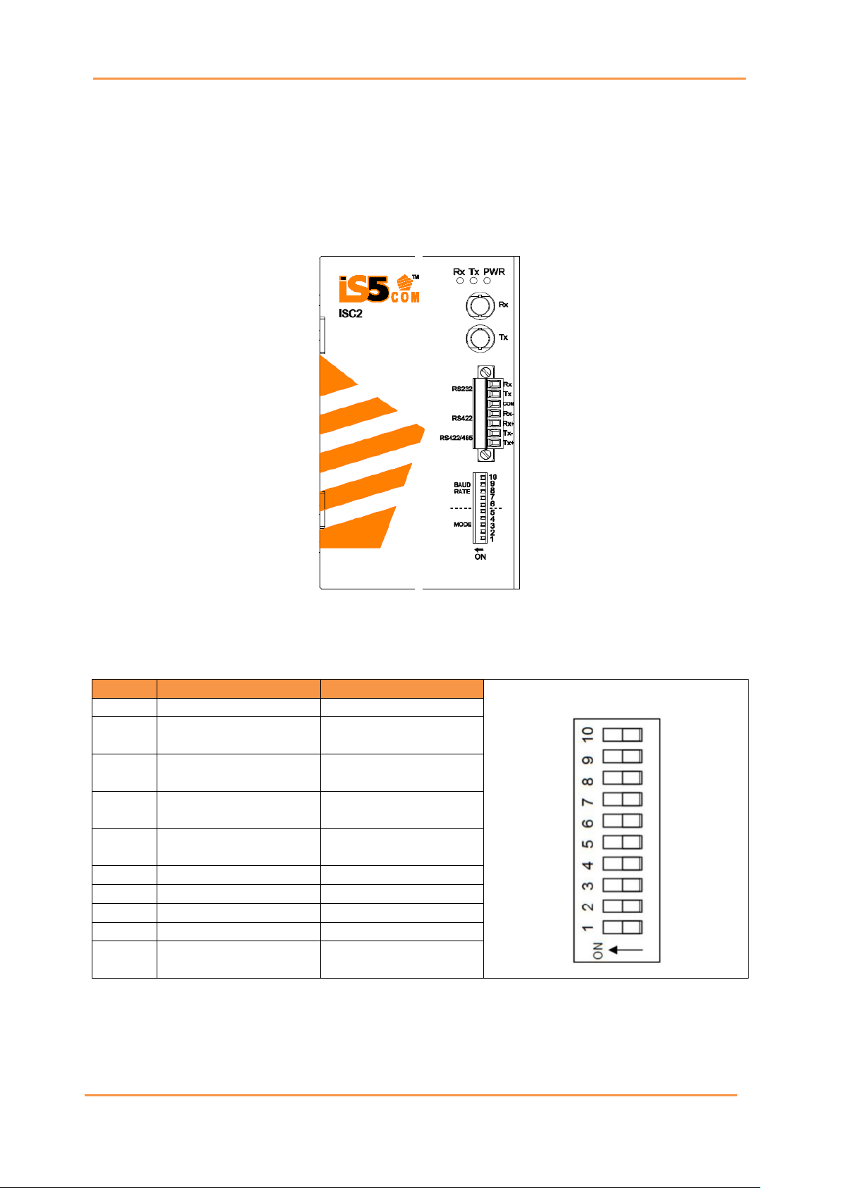
The iSC2F supports the following functions:
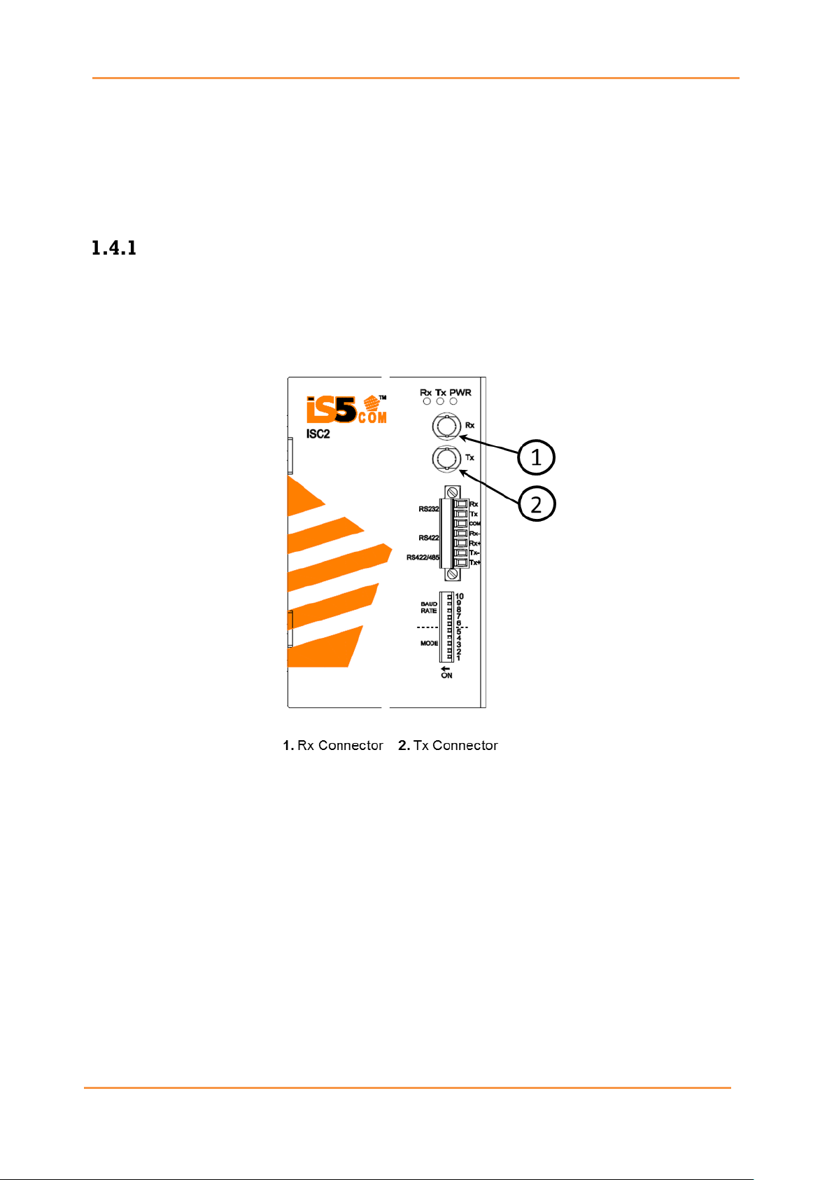
•Two-wire RS232 compliant (TX, RX)
•Two-wire RS485 half-duplex compliant (D+, D-)
•Four-wire RS485/422 full-duplex compliant (TX+, TX-, RX+, RX-)
•Switch selectable 120 Ωterminations
•Up to 5 km multimode fiber
•Selectable Fiber Repeater Mode (fiber in -> fiber out)
•TX/RX LED indicators on RS232/485/422 traffic
•Configurable RS485 half-duplex turn-around time
•1200-115200 baud supported
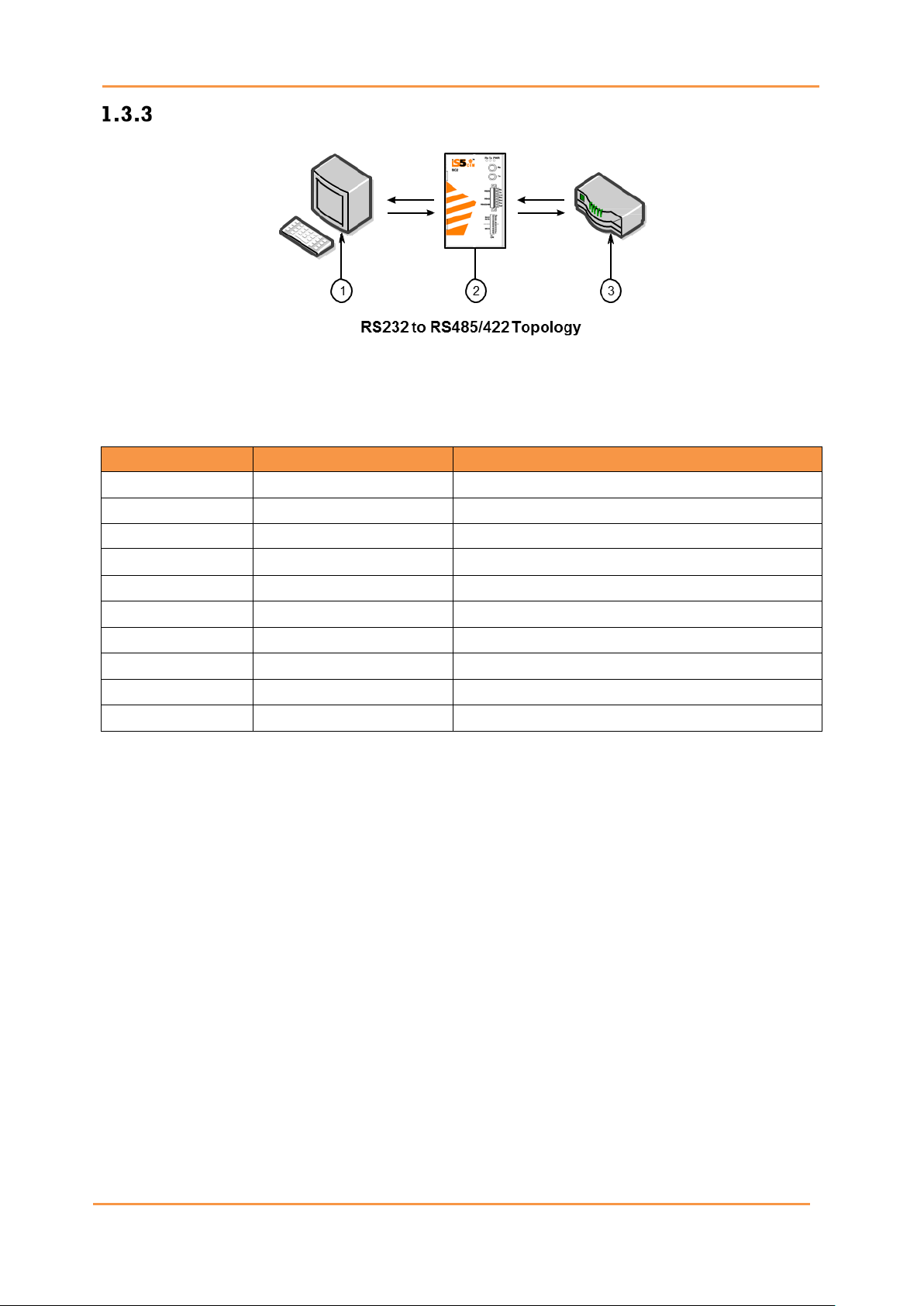
The ISC2F is equipped to provide conversion from serial (RS232, RS485, or RS422) to fiber
optics or between serial standards (RS232 to RS485 / RS422).
Serial to fiber optical conversion connections can be:
•Point-to-Point
•Fiber Repeater Mode
•Standard Serial Connection
By using the DIP switches, iSC2F can be used in the following operating modes.

iSC2F User’s
Manual
UM-iSC2F-2-EN.docx Pages 2 of 12
1.2 Operating Modes
1.3 Configuring the Device
The ISC2F can be configured using the Mode DIP switch located on the right side off
the enclosure. Use the DIP switch to change the operating mode of the ISC2F.
The configuration settings are as follows:
Switch
ON
OFF
1
RS232 to fiber
RS485/422 to fiber
2 RS232-to-RS485/422
conversion enabled
RS232-to-RS485/422
conversion disabled
3
Full-duplex
Half-duplex (RS485
only)
4
120Ωterminations
enabled
No 120Ωtermination
5
Fiber repeater
enabled
Fiber repeater
disabled
6
1200 – 2400 baud
n/a
7
4800 – 9600 baud
n/a
8
14400 – 19200 baud
n/a
9
28800 – 38400 baud
n/a
10 57600 – 115200
baud
n/a

iSC2F User’s
Manual
UM-iSC2F-2-EN.docx Pages 3 of 12
Serial-to-Fiber Conversion—Point-to-Point
1. RS232 device
2. iSC2F
3. RS485 Device/ Network
Note that the distance between the two ISC2F devices should be less than 5 km (3.1 mi).
RS232 Device
Position
State
Notes
1
ON
RS232 to fiber
2
OFF
RS232-to-RS485/422 conversion
3
ON/OFF
Full-duplex (485-4W or 485-2W)
4
OFF
No 120 Ωtermination
5
OFF
Fiber repeater
Note: Position 3 applies to RS485 only.
RS422/RS485 Device
Position
State
Notes
1
OFF
RS232 to fiber
2
OFF
RS232-to-RS485/422 conversion
3
ON
Full-duplex
4
OFF
No 120 Ωtermination
5
OFF
Fiber repeater
In this mode, serial data is converted directly into light signal and transmitted over multi-
mode fiber optics. The serial standard is selected by Position 1 of the DIP switches: OFF
(default) is for RS485/RS422, and ON is for RS232. Position 2 should be OFF for serial to fiber
conversion. Position 6-10 should be configured if RS485 communications are used, to have
the appropriate turn-around timer shown below selected. Positions 6-10 do not impact
communications in full-duplex mode.

iSC2F User’s
Manual
UM-iSC2F-2-EN.docx Pages 4 of 12
Baud Rate (bps)
DIP6
DIP7
DIP8
DIP9
DIP10
1200 – 2400
ON
OFF
OFF
OFF
OFF
4800 – 9600
OFF
ON
OFF
OFF
OFF
14400 – 19200 OFF OFF ON OFF OFF
28800 – 38400 OFF OFF OFF ON OFF
57600 – 115200 OFF OFF OFF OFF ON
Fiber Repeater Mode
When a distance that is more than 5 km (3.1 mi) has to be supported, iSC2F must be used in
Fiber Repeater mode. This mode supports extended distance between serial devices.
1. RS232 device
2. iSC2F
3. RS485 Device/ Network
Position
State
Notes
1
OFF
RS232 to fiber
2
OFF
RS232-to-RS485/422 conversion
3
OFF
Full-duplex
4
OFF
No 120 Ohm termination
5
ON
Fiber repeater
6
OFF
1200 – 2400 baud
7
OFF
4800 – 9600 baud
8
OFF
14400 – 19200 baud
9
OFF
28800 – 38400 baud
10
OFF
57600 – 115200 baud
The repeat function will optically re-transmit any data received on the optical receiver, in
addition to any connected serial devices. As a result, any data transmitted from the master,
will be re-transmitted optically to the slave. In this case, the distance between master and
slave can be extended over the 5 km (3.1 mi).
This topology can be used for RS232, RS485 or RS422. In all cases, all repeater devices should
have the repeat function—DIP position 5 ON.

iSC2F User’s
Manual
UM-iSC2F-2-EN.docx Pages 5 of 12
Serial Standard Conversion
1. RS232 device
2. iSC2F
3. RS485 Device/ Network
Position
State
Notes
1
OFF
RS232 to fiber
2
ON
RS232-to-RS485/422 conversion
3
ON/OFF
Full-duplex
4
OFF
No 120 Ωtermination
5
OFF
Fiber repeater
6
ON/OFF
1200 – 2400 baud
7
ON/OFF
4800 – 9600 baud
8
ON/OFF
14400 – 19200 baud
9
ON/OFF
28800 – 38400 baud
10
ON/OFF
57600 – 115200 baud
In this mode of operation, RS232 voltage levels are converted to the appropriate RS485 or
RS422 signaling levels depending on the DIP switch configuration. In this mode of operation
position 2 of the DIP switches must be in the ON position when operation position of switch 1
is OFF.
Position 6 – 10 of the DIP switches must reflect the proper operating baud rate.
NOTE
In this mode of operation, no isolation is provided between RS232 device and the RS485/422
network– both devices share the same common terminal. It should be noted that the common
terminal on RS232 devices is connected to ground. In some instances (i.e. when connecting
to large RS485 networks), it may be preferential for the user to leave the RS485/RS422 shield
terminal unconnected to the ISC2F in this mode.

iSC2F User’s
Manual
UM-iSC2F-2-EN.docx Pages 6 of 12
1.4 Communication Ports
The iSC2F can be equipped with various types of communication ports to enhance its
abilities and performance. To determine which ports are equipped on the device, refer
to the factory data file available in specification.
Fiber Optic Ports
Fiber optic ports are available with ST (Straight Tip) connectors. Make sure the Transmit
(Tx) and Receive (Rx) connections of each port are properly connected and matched to
establish a proper link.

iSC2F User’s
Manual
UM-iSC2F-2-EN.docx Pages 7 of 12
Serial Terminal
The ISC2F is equipped with a seven-terminal Phoenix-style connector. This connector can
accommodate one RS232 connection, and one RS485/422 connection. The following is the pin-
out for the serial terminal:
Pin #
Signal
J2
1 (top) RS232 RX
2 RS232 TX
3 Common
4 RS422 RX-
5 RS422 RX+
6 RS422 TX- / RS485 D-
7 (bottom) RS422 TX+ / RS485 D+

iSC2F User’s
Manual
UM-iSC2F-2-EN.docx Pages 8 of 12
HARDWARE OVERVIEW
2.1 Front Panel
The ISC2F features various ports, controls and indicator LEDs on the front panel for
configuring and troubleshooting the device.
Number
Description
Function
1 Power Indicator LED The power indicator LED illuminates when power
is being supplied to the device.
2 Tx LED Tx LED illuminates when traffic is transmitted to
Serial Interface.
3 RX LED Rx LED illuminates when traffic is received from
Serial Interface.
4 Mode Selector Switch
This switch sets the device in transparent, half-
duplex (HDX), full-
duplex (FDX) or reserved
mode.

iSC2F User’s
Manual
UM-iSC2F-2-EN.docx Pages 9 of 12
2.3 Power Supply Connections
The Phillips Screw Terminal Block, located on the bottom of the unit, has Phillips screws
with compression plates, allowing either bare wire connections or crimped terminal lugs.
The use of #6 size ring lugs is recommended to ensure secure and reliable connections
under severe shock or vibration. The terminal block comes with a safety cover which
must be removed before connecting any wires. This cover must be re-attached after
wiring to ensure personnel safety.
The iSC2F supports a single power supply (PWR1) with 4 options:
1. LV: Dual Input 9-36VDC
2. MV: Dual Input Supply 36-75VDC
3. HV: Single universal Input 110-370VDC
4. HV: Single universal Input 90-264VAC.
Terminal Block (for option 4)
Terminal
Number
Description Connection
1 PWR1 (L) – Live Connect to the (Live) of DC power supply 1 or (Live)
terminal of an AC power source.
2 PWR1 (G) – Ground DC Power supply 1 ground connection or AC power
round connection.
3 PWR1 (N) – Neutral Connect to the Neutral of the DC power supply 1 or
(Neutral) terminal of an AC power source.
4 G – Chassis Ground
Connected to the ground bus for DC inputs or Safety
Ground terminal for AC Units. Chassis Ground
connects to both power supply surge grounds via a
removable jumper.
Note:
Options 1,2, and 3 don’t include terminal blocks. The DV power connection should be done
based on the diagram of the supplied chassis.
Power Supply Connection
Chassis Ground Connection
The iSC2F chassis ground connection, located next to the terminal block, uses a #6-32
Screw. We recommend terminating the ground connection using a #6 ring lug, and a torque
setting of 15 in.lbs (1.7Nm).
100-240VAC rated equipment: A 250VAC appropriately rated circuit breaker must be
installed.
Equipment must be installed according to the applicable country wiring codes.
110-370VDC rated equipment: A 370VDC appropriately rated circuit breaker must be
installed.
A circuit breaker is not required for DC power supply voltages of 9-48VDC.
Equipment must be installed according to the applicable country wiring codes.

iSC2F User’s
Manual
UM-iSC2F-2-EN.docx Pages 10 of 12
Hardware Installation
The ISC2F is designed for maximum mounting and display flexibility. It can be equipped with
connectors that allow it to be installed in a DIN rail.
3.1 DIN Rail Installation
For DIN rail installations, the ISC2F can be equipped with a DIN rail bracket pre-installed
on the back of the chassis. The bracket allows the device to be slid onto a standard 35
mm (1.4 in) DIN rail.
To mount the device to a DIN rail, perform the following:
1.
Align the slot in the bracket with the DIN rail.
2.
Pull the release on the bracket down and slide the device onto the DIN rail. If
necessary, use a screw driver to unlock the release. Let go of the release to lock the
device in position.
Step 1 Step 2

iSC2F User’s
Manual
UM-iSC2F-2-EN.docx Pages 11 of 12
3.2 Dimensions
All dimensions are shown in inches.

iSC2F User’s
Manual
UM-iSC2F-2-EN.docx Pages 12 of 12
SPECIFICATIONS
Model Number iSC2F
Physical Ports
10M Fiber port 1
RS232/RS422/RS485 1 (2 for RS232 to RS485 conversion)
Power
Input power
Dual DC Inputs of 9-36VDC or Dual Input 36-75VDC, or single Input 110-370VDC or 90-
264VAC
Power consumption (Typ.) 5 Watts
Overload current
protection
Present
Reverse polarity
protection
Present on terminal block
Physical Characteristics
Enclosure IP-40 Galvanized Steel
Dimension (W x D x H) 76.2(W) x 92.8(D) x 148.3(H)mm (3.0 x 3.65 x 5.84 inches)
Weight (g) ~1000 g
Environmental
Storage Temperature -40oC to +85oC (-40oto 185oF)
Operating Temperature -40oC to +85oC (-40oto 185oF)
Operating Humidity 5% to 95% Non-condensing
Regulatory Approvals
EMI FCC Part 15, CISPR (EN55022) class A, EN50155 (EN50121-3-2, EN55011, EN50121-4)
EMS EN61000-4-2 (ESD), EN61000-4-3 (RS), EN61000-4-4 (EFT), EN61000-4-5 (Surge),
EN61000-4-6 (CS), EN61000-4-8, EN61000-4-11
Shock IEC60068-2-27
Free Fall IEC60068-2-32
Vibration IEC60068-2-6
Safety EN60950-1
Warranty
Warranty 5 Years
Table of contents
Other IS5 COMMUNICATIONS Media Converter manuals
Popular Media Converter manuals by other brands

American Dynamics
American Dynamics VideoEdge Architect & engineer Specification

Converters.TV
Converters.TV 998 Scan converter Operation manual

PRIZM
PRIZM 201350 Series User's manual and troubleshooting guide

Usl
Usl DAX-602 instruction manual

M-system
M-system M8YV instruction manual

Transition Networks
Transition Networks CBFTF10XX-15X user guide