hilscher PKV 30-COS Application guide

Device manual
PKV 30-COS
Protocol converter for CANopen Slave
Hilscher Gesellschaft für Systemautomation mbH
Rheinstraße 15
D-65795 Hattersheim
Germany
Tel. +49 (0) 6190/9907-0
Fax. +49 (0) 6190/9907-50
Sales: +49 (0) 6190/9907-0
Hotline and Support: +49 (0) 6190/9907-99
Homepage: http://www.hilscher.com

Index Date Device Device
number Chapter Revision
227.09.99 PKV 30-COS G9918001 All Translation from german manual
316.11.01 PKV 30-COS G9918001 2.31 Remark to CTS signal by RS232 physic added
Although this device has been developed with great care and intensively tested, Hilscher Gesellschaft für
Systemautomation mbH cannot guarantee the suitability of this device for any purpose not confirmed by
us in writing.
Guarantee claims shall be limited to the right to require rectification. Liability for any damages which
may have arisen from the use of this device or its documentation shall be limited to cases of intent.
We reserve the right to modify our products and their specifications at any time in as far as this contribu-
tes to technical progress. The version of the manual supplied with the device applies.
List of Revisions 2
Copyright * Hilscher Gesellschaft für Systemautomation mbH * Hotline/Support: +49(0)6190/9907-99 * De:P30COS#3E

1 Introduction ...................................................................................... 4........
1.1 Scope of Performance ......................................................................... 4........
2 General Device Description ....................................................................... 5........
2.1 Configuration ................................................................................ 6........
2.1.1 Settings of the Serial Interface Type ..................................................... 6........
2.1.2 Setting the CANopen Station Address ................................................... 6........
2.2 Connecting the supply voltage (X1) ........................................................... 7........
2.3 Serial Interfaces .............................................................................. 8........
2.3.1 First non-floating interface (X3) ........................................................ 8........
2.3.2 Potential-Free CANopen Interface (X2) ................................................. 10.......
2.3.3 CANopen Cable and Connection ........................................................ 11.......
2.3.4 Bus Termination ........................................................................ 11.......
2.4 Diagnostic ................................................................................... 12.......
2.4.1 Activating the diagnostic/configuration operation ....................................... 13.......
2.5 Status Displays ............................................................................... 14.......
2.6 Mechanical Dimensions ...................................................................... 15.......
3 Appendix ......................................................................................... 16.......
3.1 Selection of the Line for the Individual Interfaces .............................................. 16.......
3.2 Installation Technique ......................................................................... 17.......
3.2.1 Installation Technique- RS232 Interface ................................................. 17.......
3.2.2 Installation Technique - RS485 / RS422 ................................................. 18.......
3.3 Grounding the Cable shield ................................................................... 19.......
3.4 Technical Data ................................................................................ 20.......
List of Revisions 3
Copyright * Hilscher Gesellschaft für Systemautomation mbH * Hotline/Support: +49(0)6190/9907-99 * De:P30COS#3E

1 Introduction
1.1 Scope of Performance
The task often consists of exchanging data between controls of various manu-
facturers or with a host computer. Every system has its own transfer protocol for
this purpose. The implementation of a protocol that is foreign to the system is of-
ten not possible or only with an unreasonable amount of difficulty. This is caused
by the following border conditions:
The interface drivers do not agree
The interface controller is not up to the task
Missing or insufficient computing capacity
Real time requirements cannot be met
Lack of possibility of providing additional configuration data
Missing or insufficient starting up and diagnostic aids
Sometimes the protocol is only used for a single installation. Yet, the implemen-
tation must satisfy extreme quality requirements. The effects of a software error
in the transfer protocol can lead to the stoppage of the whole plant and cause un-
foreseen costs.
Experience has shown that it is just these tests and acceptance of implementation
that are carried out partly only in the laboratory or on a hardly functional installa-
tion. Despite great care, it can then occur that an error is first discovered in the
proper operation of the plant. Especially when the error occurs sporadically or is
dependent on particular plant conditions then an error localization without inte-
grated diagnosis functions is only possible with the greatest of luck.
Practice has shown that most of the problems arise not through errors in imple-
mentation but through poor agreement at the user level. Partly the telegram lan-
guages between the coupling partners are incomplete or are not adhered to. Thus,
for instance, telegrams are expected that have not been sent at all or a telegram
has been interchanged. If the telegram traffic can also be written, then the pro-
blem is quickly solved.
The Protocol Converter is a device that has been specially developed for this pur-
pose and with its operating system makes all the functions available that are
necessary for a rational and reliable implementation of coupling protocols.
The PKV 30-COS Protocol Converter possesses two communication interfaces,
of which one is designed as a CANopen interface.
Introduction 4
Copyright * Hilscher Gesellschaft für Systemautomation mbH * Hotline/Support: +49(0)6190/9907-99 * De:P30COS#3E
2 General Device Description
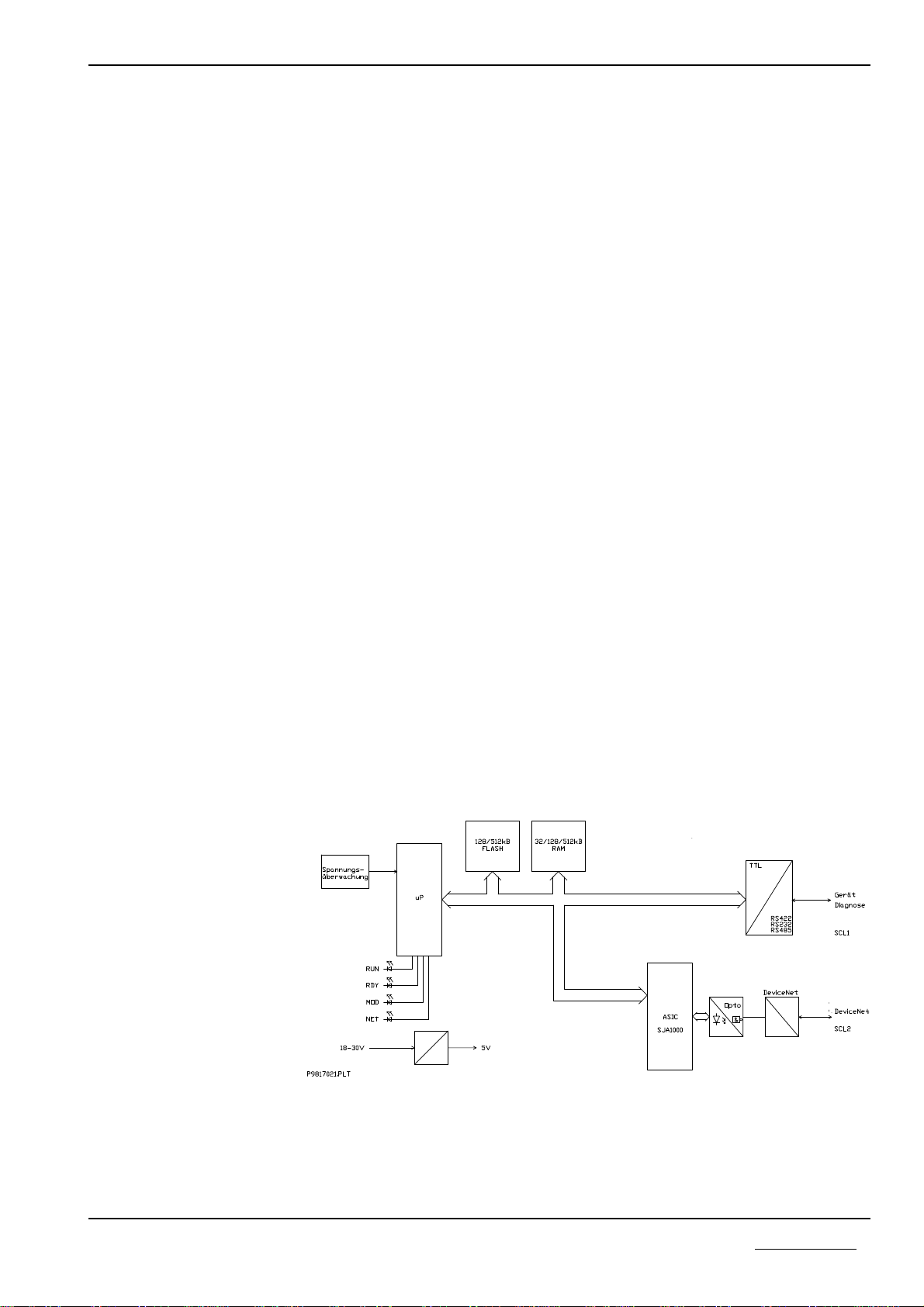
The Protocol Converter consists of a basic circuit board and a power supply
circuit board with DC/DC transformers in which all the required auxiliary volta-
ges are created.
The AM188ES processor is inserted on to the basic circuit board. It contains a
built-in timer, interrupt- and DMA-Controller, 2 serial interfaces and thus requi-
res only a few external nodules. The computing power is adequate for processing
even large quantities of data. Furthermore, the 16 Bit processor ensures efficient
software development in a high level language.
The Firmware and the configuration data are stored in a FLASH-EPROM. This
can be programmed within the circuits and retains its data even when the opera-
ting voltage is switched off.
The serial interfaces are realized by the microprocessor and the ASIC SJA1000.
The device to be connected is linked with the first non-floating interface. A
choice can be made between a RS232C, RS422- or a RS485 interface with the aid
of a plug-in jumper. The second potential-free interface is designed for use at the
CANopen.
The proper function of the Protocol Converter is monitored by the internal
Watchdog of the micro- processor and the internal operating voltage by means of
the MAX809 module. In the case of error, these monitors trigger a Reset at the
processor.
The internal supply voltage is generated by means of a switched mode regulator.
Its input voltage is filtered via a current-transformed toroidal choke and filter ca-
pacitors. A transient diode is available as spike and polarity reversal protection.
In the case of malfunction, a semiconductor fuse switches the device down to a
low residual current until the malfunction is cleared. This means that the chan-
ging of an internal sensitive fuse is dispensed with. Besides this, a charging ca-
pacitor is available that blocks the voltage dips that occur in the switching of
fuses.The operational readiness and an error in the communication interface of
the Protocol Converter as well as the CANopen status are displayed by LEDs.
Block diagram of the PKV30-COS Protocol Converter.
Spannumgsüberwachung = Voltage supervision. Gerät diagnose = Device diagnostic
General Device Description 5
Copyright * Hilscher Gesellschaft für Systemautomation mbH * Hotline/Support: +49(0)6190/9907-99 * De:P30COS#3E

2.1 Configuration
2.1.1 Settings of the Serial Interface Type
The hardware of the PKV need only be configured via a J5 plug-in jumper rail in
order to set the various interface types. This rail can be reached when the front
face of the PKV 30-COS facing the two serial interfaces is removed. For this pur-
pose the four screws at the corners of the front face must be released. The sketch
below shows the position of the plug-in jumper rail as seen from the front face.
The interface type can be selected with the aid of the table. The various interface
types are discussed in greater detail in the following chapters.
Setting Jumper J5 Interface type
open RS232
3-4 RS485
1-2, 3-4 RS422
Settings of the serial interface type
2.1.2 Setting the CANopen Station Address
The setting of the CANopen station address (1-127) is carried out by means of
the two coding switches. The assignment is shown in the chapter “Mechanical
Dimensions”.
Plug 9-pole DSub Plug
14 3 2
Plug rail
Front face view of the PKV 30-COS with plug rail
Seriel Interface CANopen Interface
14 3 2
General Device Description 6
Copyright * Hilscher Gesellschaft für Systemautomation mbH * Hotline/Support: +49(0)6190/9907-99 * De:P30COS#3E

2.2 Connecting the supply voltage (X1)
The Protocol Converter requires a supply voltage of 24 Volt. The maximum po-
wer consumption is given in the chapter on “Technical Data”. A three-phase
rectified supply or a simple rectified switching with charge capacitor is sufficient.
The supply voltage must be led to ground. It is connected by means of a plug-in
screwed clamp. Use is made of a 3-pole COMBICON plug from the PHOENIX
company (MSTB 2,5/3-ST-5,08).
Connection Symbol Signal
1+24V +24V supply voltage
20V Reference potential
3PE Equipment grounding conductor
Connector pin assignment of the operating voltage connection X1
General Device Description 7
Copyright * Hilscher Gesellschaft für Systemautomation mbH * Hotline/Support: +49(0)6190/9907-99 * De:P30COS#3E
2.3 Serial Interfaces
The PKV 30-COS possesses two independent interfaces.
First Serial Interface (X3). The first interface cab be selected to operate as a
communication RS232C-, RS422-, or RS485 interface or as a diagnosis / configu-
ration interface. The setting of the communication interface takes place over
plug-in jumpers at J5 (see also chapter “Configuration”).
Second Serial Interface (X2). The second serial interface is designed for opera-
tion at the CANopen.
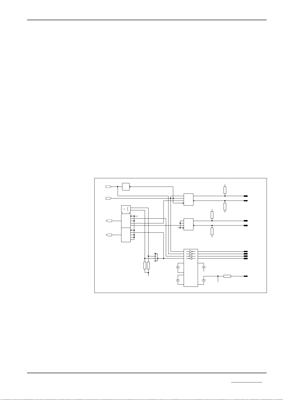
2.3.1 First non-floating interface (X3)
This interface with a 9 pole D-Sub plug to DIN 41652 serves for connecting a de-
vice and can be configured as RS232-, RS422-, or RS485 interface. The setting
takes place over plug-in jumpers at J5 (see also “Configuration”).
In the same way a diagnosis/configuration of the device is possible. The activati-
on of the diagnosis/configuration operation is described in the chapter “Acti-
vating the Diagnostic/Configuration Operation” in this manual.
3
1
2
3
4
8
2
9
5
6
1
4
89
14
2
1
6
5
4
3
15
10
11
12
13
7
9
7
4
3
1
2
6
7
4
3
1
2
6
7
11
10
12
9
1
3
4
5
14
7
13
8
2
6
R29
X3
J5
X3
X3
X3
X3
C13
C15
C12
C14
R34
X3
X3
X3
R30
R32
R35
D7
D8
X3
R36
N2
R33
N1
D6
1
MUX
Y
Y
3
2
1
0
EN
3
2
1
0
EN
3
0G1
0
D
DE
R
RE
A
B
D
DE
R
RE
A
B
C1+
C1-
C2+
C2-
V+
V-
74HCT04
74HCT153
MAX202E
10k
100n
100n
100n
100n
100
10k
10k
10k 10k
ADM485JR 10k
ADM485JR
P9809S12.HP
RXD1
TXD1
CTS1
RGND1
RX/TXD1B
RTSA
RTS1
RXD1A
EN485
EN422
TXDA
RX/TXD1A
RXD1B
GND
GND
GND
GND
GND
GND
CTSA
RXDA
+5V
+5V
+5V
Output circuit of the first serial interface X3
General Device Description 8
Copyright * Hilscher Gesellschaft für Systemautomation mbH * Hotline/Support: +49(0)6190/9907-99 * De:P30COS#3E

In the following table the pin assignment of the signals used for the various inter-
face types is shown. All unused signals must not be used. The Bus terminators
must be selected in accordance with the application and must be soldered into the
plug. The resistors R29 and R30 as well as R32 and R33 in the output circuit ser-
ve for setting the quiescent point circuit on the RS485-/RS422 Bus. All resistors
have a resistance value of 10 kOhm.
Connection Input/
Output Signal-
designation Signal RS
485 RS
422 RS
232
1Input/
Output RXD/TXD-N
TXD-N Send data inverted RS 422
Data inverted RS 485 ü ü
2Input RXD Receive data RS 232 ü
3Output TXD Send data RS 232 ü
4Input RXD-P Receive data RS 422 ü
5RGND Reference potential over 100
Ohm ü ü ü
6Input/
Output RXD/TXD-P
TXD-P Send data RS 422
Data RS485 ü ü
7Output RTS Switch on send portion ü
8Input CTS Send readiness ü
9Input RXD-N Receipt data inverted RS 422 ü
Pin assignment of the first interface for X3
Remarks:
When using the RS232 interface, only the connections that are marked with a
tick are to be used.
When using the RS232 interface, the signal CTS (pin 8, Send readiness) must
be activated, this mean pulled up to +5V. For example, this could happen by
connecting the pins 4, 6 and 8 in the plug. This connections are realized also
in the diagnostic cable CAB-SRV of company Hilscher.
General Device Description 9
Copyright * Hilscher Gesellschaft für Systemautomation mbH * Hotline/Support: +49(0)6190/9907-99 * De:P30COS#3E
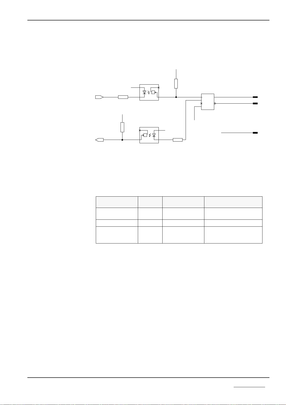
2.3.2 Potential-Free CANopen Interface (X2)
The potential-free CANopen interface is led outward via a 9 pole Dsub
connection.
Circuit of the CANopen interface X2
Connection
DSub Input/
Output Signal
CANopen Signal
2Input/
Output CAN_Low Receive/Send data Low
3ISOGND Data reference potential
7Input/
Output CAN_High Receive/Send data High
Pin assignment of the CANopen interface X2
X2
N4
R22
&
U3
R20
R21
R19
&
U2
X2
X2
L
H
Rs
REF
RX
TX
PCA82C251
680 HCPL0601
680
680
680
HCPL0601
RX
TX 71
4
5
8
7
6
2
3
7
6
2
3
7
6
3
2
12
12
1
2
1
2
ISO+5V
ISO+5V
ISOGND
ISOGND
CAN_HIGH
CAN_LOW
+5V
+5V
General Device Description 10
Copyright * Hilscher Gesellschaft für Systemautomation mbH * Hotline/Support: +49(0)6190/9907-99 * De:P30COS#3E
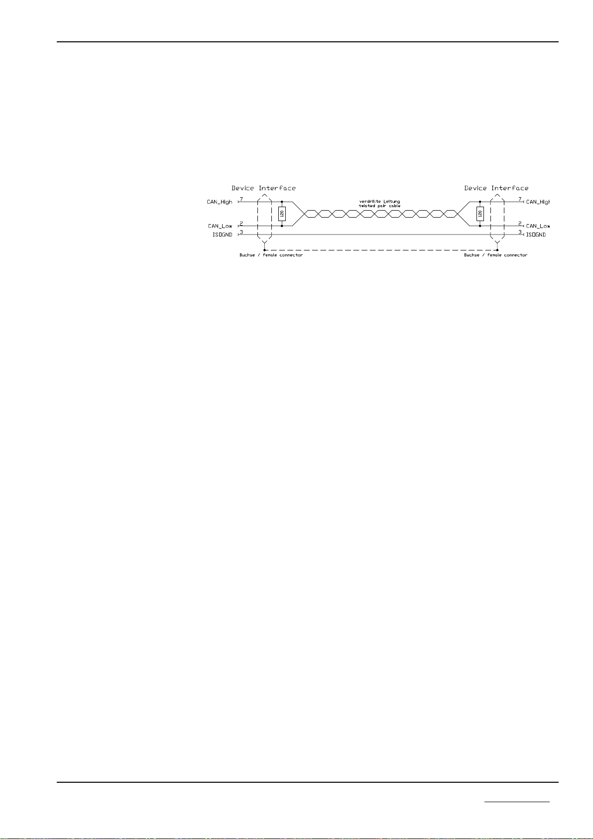
2.3.3 CANopen Cable and Connection
Only cable types specially certified for CANopen should be used as cable con-
nections. The following figure shows the minimum wiring between two network
participants. Please note that at the end and at the start of the Bus line closing re-
sistances of each 120 Ohm must be attached.
Connecting cable between Protocol Converter and the CANopen Master
2.3.4 Bus Termination
The 120 Ohm closing resistors of the network must be connected for correct ope-
ration of the two Bus lines.
General Device Description 11
Copyright * Hilscher Gesellschaft für Systemautomation mbH * Hotline/Support: +49(0)6190/9907-99 * De:P30COS#3E
2.4 Diagnostic
The connection of a PC to the Protocol Converter is also possible over the first
serial interface (X3). It corresponds to the RS232C standard according to CCITT
or DIN. Here, only the necessary signals are available.
The following control signals are processed or evaluated as follows:
RTS is set to High in accordance with the functional readiness and is not
changed again.
CTS must be connected via a wire bridge with pins 4 and 8 of the D-Sub plug.
The transfer between PC and Protocol Converter is carried out at 9600 Baud and
the following data format: 8 data Bits, 1 Sop Bit and even parity. The A3964R
procedure is used as transfer protocol.
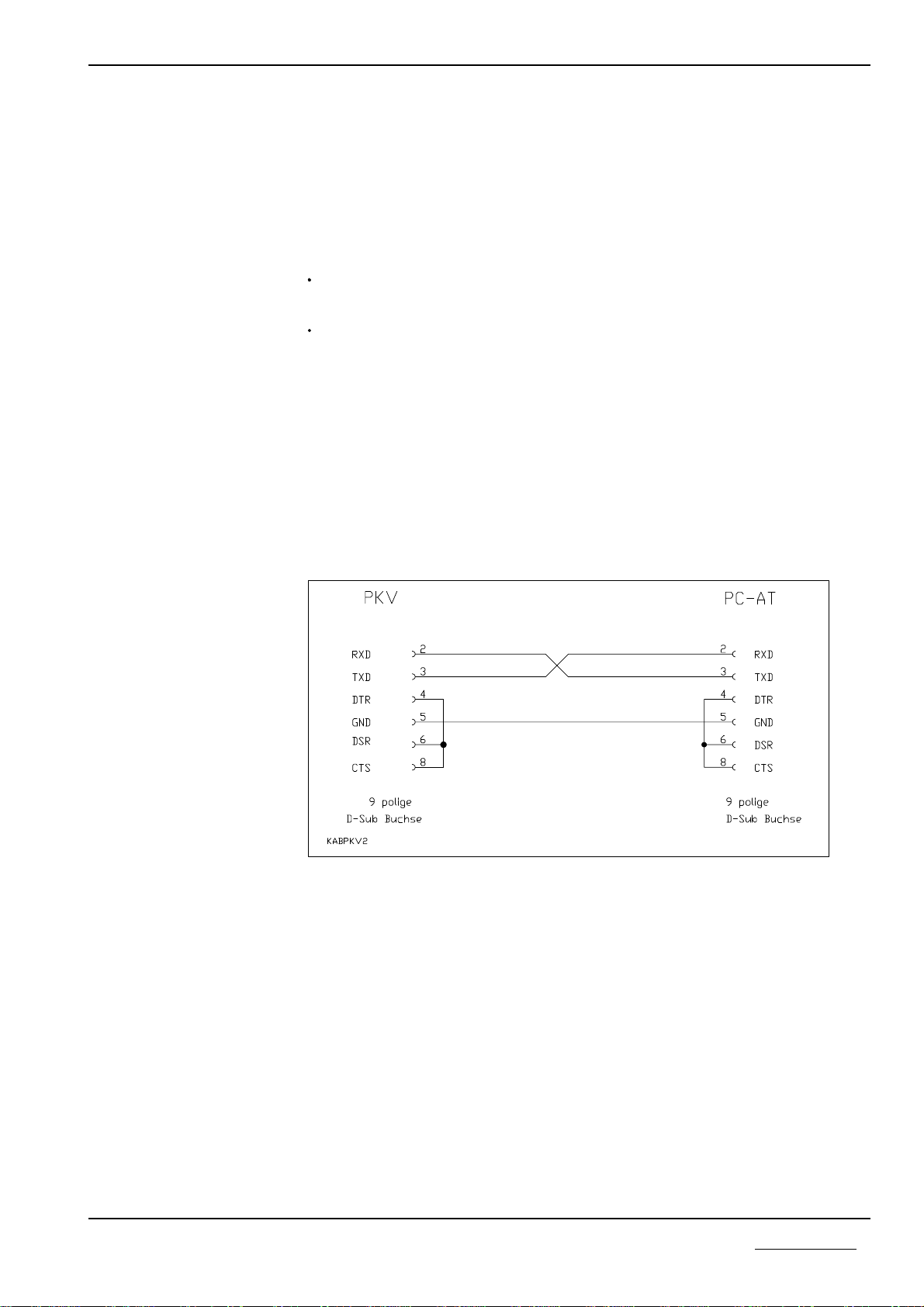
The connection of the PC is carried out by means of a three-pole cable which
must not be longer than 15 meters. The wiring of the cable is shown below. For
better interference rejection, the cable shield should be grounded on the PC side
to the plug housing.
Connecting cable between Protocol Converter and PC
General Device Description 12
Copyright * Hilscher Gesellschaft für Systemautomation mbH * Hotline/Support: +49(0)6190/9907-99 * De:P30COS#3E

The connection X3 of the PKV 30-COS is meant for
communication operation
or for
diagnostic/configuration operation
When switching on the 30-COS a check is carried out at the X3 connection whe-
ther the diagnosis/configuration operation is to be started. In the other case, com-
munication operation is taken up.
2.4.1 Activating the diagnostic/configuration operation
The diagnosis cable must be connected to X3 at the Protocol Converter and to the
COM1 (or COM2) of the PC.
Start ComPro program with
COMPRO /S:1 or.COMPRO /S:2
(for COM1 or COM2).
Select menu Online - System - Bootstart first. The window with the: The system
will be reseted and the bootloader becomes active without startinmg any firmwa-
re message appears.
Now switch off the currant at the Protocol Converter and wait at least for 10
seconds.
In the ComPro confirm the: The system will be reseted and the bootloader be-
comes active without startinmg any firmware message with Return. A red win-
dow appears with the message: Waiting for hardware receipt.
Then the voltage at the Protocol Converter is switched on again.
The red window in the ComPro must disappear.
In order to test whether the Protocol Converter is in diagnostic operation, select
the Online - System - Firmware menu sequence. When the information of the
Firmware in the Converter appears, then the diagnostic/configuration operation
has been successfully activated. If the: No connection could be built up message
appears, then the steps described for activating the diagnostic/configuration ope-
ration must be carried out again.
When the interface type
RS422 or RS485 is configu-
red, it is not necessary to
change this configuration for
diagnostic operation.
General Device Description 13
Copyright * Hilscher Gesellschaft für Systemautomation mbH * Hotline/Support: +49(0)6190/9907-99 * De:P30COS#3E
2.5 Status Displays
There are four LEDs available of the PKV 30-COS for status displays:
Display Color Condition Meaning
With a device defect, the conti-
nuous accessing of the Watchdog
Supervision can also lead to a cy-
clic blinking of the RDY-LED.
RDY yellow On
Blinks cyclically
Blinks irregularly
Off
PKV ready
Bootstraploader active
Hardware- or system error
Hardware defective
RUN green On
Blinks irregularly
see below
Off
Communication running
Parameter error
no communication
ERR 1 yellow Lights up briefly CAN message sent
- No error shows communication
operation is on
ERR 2 red on The device is not currently in an
operational condition but did once
reach operational readiness. This
means that a running
communication to the Master has
been interrupted.
After switching on, the PKV carries out a self-test. If this has been run through
successfully, then the yellow RDY-LED is switched on. Otherwise the LED be-
gins to blink irregularly and the further processing of the program is aborted.
If no field bus Firmware is loaded on the PKV, then the Bootstrap loader shows
this by a cyclical blinking of the RDY-LED in a 1-second rhythm.. During the
loading of the Firmware, the blink rhythm increases to approximately 5 Hz.
If the LED remains off, then there is a defect of the PKV.
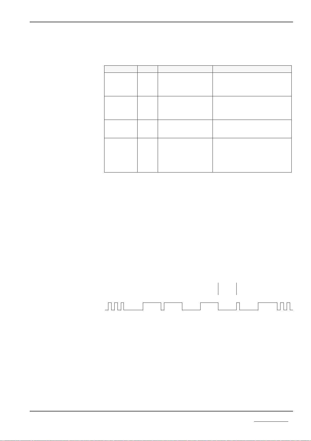
If a Protocol Task recognizes parametrizing error, then the Task is displayed by
the RUN-LED in accordance with the following figure. If there is no error and
communication could be started, then the RUN-LED is switched on. If the com-
munication operation is blocked, then the RUN-LED remains off.
Start
identifier Data bits with depatartion identifier -> 1 sec. <- starts
again
The display on the LED is carried
out from left to right
RCS
with
DBM
error
Task 1
without
error
Task 2
without
error
Task 3
with
error
Task 4
without
error
Task 5
with
error
Task 6
with
error
Task 7
not confi-
gured
Display of the tasks that have indicated a parametrizing error
General Device Description 14
Copyright * Hilscher Gesellschaft für Systemautomation mbH * Hotline/Support: +49(0)6190/9907-99 * De:P30COS#3E

2.6 Mechanical Dimensions
The Gateway is built into an aluminum profile housing. This permits direct instal-
lation into the switching cupboard on a carrier rail (TS35 according to DIN EN
50022). The mechanical dimensions and the allocation of the pins are shown in
the following figures.
LED-Anzeige = LED display, Spannungsversorgung = Voltage supply,
serielle Schnittstelle = serial Interface
Pin assignment on the Protocol Converter
Mechanical dimensions of the Protocol Converter for clipping on to a carrier rail
The depth of the converter is approximately 80 mm.
To set the interface type, open
the top cover ------------>
105
105
General Device Description 15
Copyright * Hilscher Gesellschaft für Systemautomation mbH * Hotline/Support: +49(0)6190/9907-99 * De:P30COS#3E

3 Appendix
3.1 Selection of the Line for the Individual Interfaces
The following table contains a review of the achievable transfer rates of the X3
interface. This depends to a large extent on the length of the transfer distance and
the line used.
Interface Line max.
Distance max.Transfer-
rate
RS232C LIYCY 3x0.25 sq. mm 15 m 19.2 kBd
RS422 LIYCY-CY 2x2x0.25 sq. mmsurge
impedance 100-150 OhmCapacitance
per unit length approx. 60 pF/m
200 m 500 kBd
1200 m 19.2 kBd
RS485 LIYCY-CY 1x2x0.25 sq. mmsurge
impedance 100-150 OhmCapacitance
per unit length approx. 60 pF/m
200 m 500 kBd
300 m 375 kBd
1200 m 62.5 kBd
Overview of the maximum transfer rate of the individual interfaces
Only cables specially certified for CANopen should be used as connecting cable
for CANopen.
Appendix 16
Copyright * Hilscher Gesellschaft für Systemautomation mbH * Hotline/Support: +49(0)6190/9907-99 * De:P30COS#3E

3.2 Installation Technique
The following sections contain information for wiring the individual interface
types.
3.2.1 Installation Technique- RS232 Interface
The RS232 or V24 interface is the standard interface for a point-to-point con-
nection between two communication devices. The RS232 interface hardly offers
freedom from interruption and is only designed for short line lengths (max. 15m).
Basically, a distinction must be made whether the serial RS232C interface is con-
nected potential-free or galvanically with the chassis of the devices. A connection
to the device chassis is only useful for the non-floating connected RS232C inter-
face. With the CIF, PKV or Gateway, this is the first serial interface that is
available fixed on the base circuit board.
The RS232C interface is designed for relatively short lengths (max. 15m) . It is
assumed that both devices are earthed to the same protective conductor potential.
If, despite this, equalizing currents over the chassis connection in the non-floating
model still occur, then they are limited by the built-in 100 Ohm resistance. If the
devices are situated further apart, than we recommend that the data are transmit-
ted over the distance with RS422 level. For connected devices, the signals are
then converted to RS232C level via an interface modem. In this way distances up
to 100 m can be bridged.
Interface modems are offered, among others by the Phoenix company, e.g. model
PSM-V24/V11-P.
Appendix 17
Copyright * Hilscher Gesellschaft für Systemautomation mbH * Hotline/Support: +49(0)6190/9907-99 * De:P30COS#3E

3.2.2 Installation Technique - RS485 / RS422
Under certain conditions, the RS485 as well as the RS422 interfaces are very free
from interference and are suitable for longer distances. Both interface types per-
mit the networking of several communication participants. The data transfer oc-
curs as a differential signal between the data line Data/Data¯¯¯¯. In contrast to the
RS485 interface, the RS422 interface utilizes separate data lines for sending and
receiving directions, thus a total of four conductors (TxData/TxData¯¯¯¯¯¯ and RxDa-
ta/RxData¯¯¯¯¯¯). The differential signal is always transferred over twisted wire pairs.
A Bus structure with RS485/RS422 has the following form:
Typical Form of a RS485/RS422 Bus structure
The main line determines the length of the communication path. It is terminated
at both ends with the terminators and preferably at the end with the level
resistance.
The Spur lines should not exceed a length of 2.5m. They are branched off via
Bus branches from the main line. In practice, so-called Bus clamps (e.g. from
Siemens) or T-pieces (e.g. from the Weidmüller company) are used as branches.
There are several possibilities regarding the wiring of the reference potential.
These have a plug for the input and output of the main line and a plug for the spur
line. As a rule in the branches, the level and/or the end resistors can be switched
on or off via Dip switches.
Wiring by means of screw clamps should be avoided as these usually lead to
transfer interferences with high Baud rates.
When using finished Bus branches, special account must be taken with the shiel-
ding concept and the pin assignment of the clamps!
Main line
Spur line (<2.5m)
Communication device
Branch / Bus clamp
2-wire RS485
4-wire RS422
End of the
main line
End of the
main line
Appendix 18
Copyright * Hilscher Gesellschaft für Systemautomation mbH * Hotline/Support: +49(0)6190/9907-99 * De:P30COS#3E

3.3 Grounding the Cable shield
Basically, a shielded cable should be used for each interface type for improving
the EMC. The best effect is achieved with a shield that is grounded at both ends.
Both ends grounded
If the communication devices are distributed over a large area, for instance in dif-
ferent rooms, then there is a danger that equalization currents flow between the
individual protective conductor potentials. In this case, it is recommended to gro-
und directly at one end only and at the other end, or at all ends, of spur lines, to
connect to the protective conductor via a foil capacitor of 100 nF/400V. This pre-
vents equalization flows as the interference currents are only grounded capacitati-
vely.
Grounding with long transfer distances and interference influences
For short transfer distances or little interference influences, a one-sided ground is
sufficient.
Grounding for short transfer distances or little interference influences
The threaded screws and the housing of the Dsub plug connections are connected
to the housing of the device and thus to its ground conductor. If a metallic plug
housing as well as a plug connector with shielding springs is utilized, then the
shield can be grounded with this. Otherwise the shield must be connected with
the protective ground by means of a separate line (worse solution).
If a capacitative connection is to be created to the protective earth, we recom-
mend that the capacitor is introduced into the separate chassis line and to envelo-
pe this with a shrink hose.
If the cable shield is misused as a reference potential, usually with RS485 inter-
faces (worse but economical solution), then special care must be taken.
Appendix 19
Copyright * Hilscher Gesellschaft für Systemautomation mbH * Hotline/Support: +49(0)6190/9907-99 * De:P30COS#3E

3.4 Technical Data
Processor 16 Bit with Timer, Interrupt- and DMA-Controller,
2 serial Interfaces, Watchdog
Memory structure 512 KByte RAM, 512 KByte FLASH
serial Interface configurable as non-floating
Diagnostic interface
RS232C-, RS422-, RS485-Interface,
max. transferrate 19.2 kBaud
Transfer formats Asynchron / Synchron
CANopen Interface ISO High Speed,
potential free,
max. transfer rate 1 MBaud
LED-Displays Operating and communication readiness of the conver-
ter, error on the serial interface SCL1,
Status CANopen
Operating voltage 18 - 30 V
Power consumption max. 0.20 A at 24 V
Operating temperature 0 - 50 Grad
Type of protection IP50
Dimensions (L x B x H) 105 x 105 x 80 mm
Installation Carrier rail DIN EN 50022
Appendix 20
Copyright * Hilscher Gesellschaft für Systemautomation mbH * Hotline/Support: +49(0)6190/9907-99 * De:P30COS#3E
Table of contents
Other hilscher Media Converter manuals


Popular Media Converter manuals by other brands


H&B
H&B TX-100 Installation and instruction manual

Bolin Technology
Bolin Technology D Series user manual

IFM Electronic
IFM Electronic Efector 400 RN30 Series Device manual

GRASS VALLEY
GRASS VALLEY KUDOSPRO ULC2000 user manual

Linear Technology
Linear Technology DC1523A Demo Manual

Lika
Lika ROTAPULS I28 Series quick start guide

Weidmuller
Weidmuller IE-MC-VL Series Hardware installation guide

Optical Systems Design
Optical Systems Design OSD2139 Series Operator's manual

Tema Telecomunicazioni
Tema Telecomunicazioni AD615/S product manual

KTI Networks
KTI Networks KGC-352 Series installation guide

Gira
Gira 0588 Series operating instructions

Lika
Lika SFA-5000-FD user guide