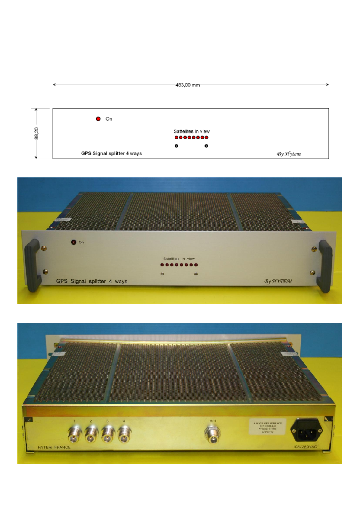
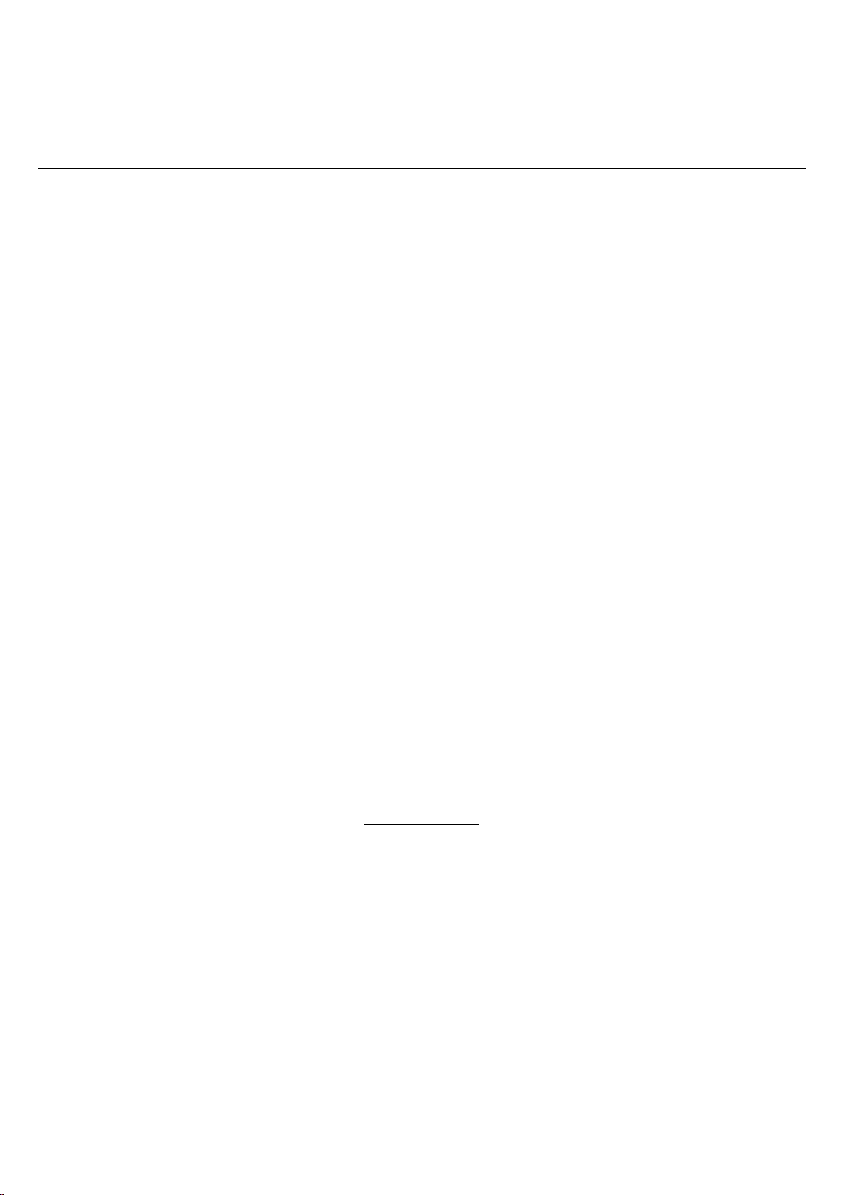
GPS signal splitter- Tiroir de répartition de signal GPS 4 voies
Type 05-02-140
HYTEM
CARACTERISTIQUES ET UTILISATION TECHNICAL SPECIFICATIONS AND USE
MAN 05-02-140
Oct 07
Guide d’installation d’un tiroir de répartition GPS
GPS subrack installation guide
Pour assurer un fonctionnement optimal de votre installation GPS, vous devez respecter ces quelques points.
To realise a good GPS intallation, you must follow these instructions
Le gain, disponible au tiroir HYTEM de répartition du système GPS doit être de 20dB minimum.
The minimum gain at the HYTEM GPS splitter subrack, must be, at least 20dB
L’antenne, fournie présente un gain de 35dB. Il convient donc de ne pas dépasser 15dB d’atténuation du signal
(coaxial) entre le tiroir et l’antenne.
Our antenna gives 35dB of gain, so you must be carreful that the losses of your feeder has no more than 15dB losses
between the antenna and the subrack
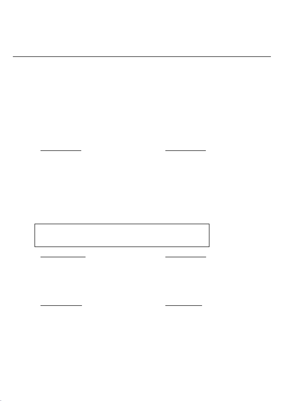
Le tiroir de répartition GPS 4 voies présente un gain total de 25dB. Ainsi, si vous avez, à l’entrée du tiroir, un
gain de ( par exemple) 24dB, le gain disponible à la sortie de ce même tiroir est de 25 + 24 = 49dB
Il suffit alors de calculer la perte maximale admissible entre votre installation et le tiroir soit 49dB (gain à la
sortie du tiroir) - 20dB (gain minimal à obtenir) = 29dB
Les pertes dans le coaxial entre le tiroir et votre installation ne devra pas excéder 13dB.
The Subrack provides a total gain of 25dB. If you have, at the antenna input (example) 24dB gain, you can easyly
calculate the gain at the output of the subrack:
25 + 24 = 49dB.
You can now calculate the max losses between the subrack and your GPS
49dB (output gain subrack) –20dB (minimal gain) = 29dB
Total losses (coaxial feeder) between the subrack and the installation must not exeed 15dB
1-calculate gain (Gin) at the HYTEM subrack
Gin = Trimble antenna –coax antenna (A) losses
In our example => Gin = 35 –11 = 24dB
2-calculate gain (Gout) at the output of the HYTEM subrack
Gout = Gin + subrack gain
In our example => Gout = 24 + 25 = 49dB
3-calculate the max coax user losses (B) (equal for each output)
Max coax user losses = Gout –20 (constant)
In our example => Max coax user losses = 49 –20 = 29dB
(to know the loss of a coaxial, please refer to: HYTEM RF & microwave cable assemblies)