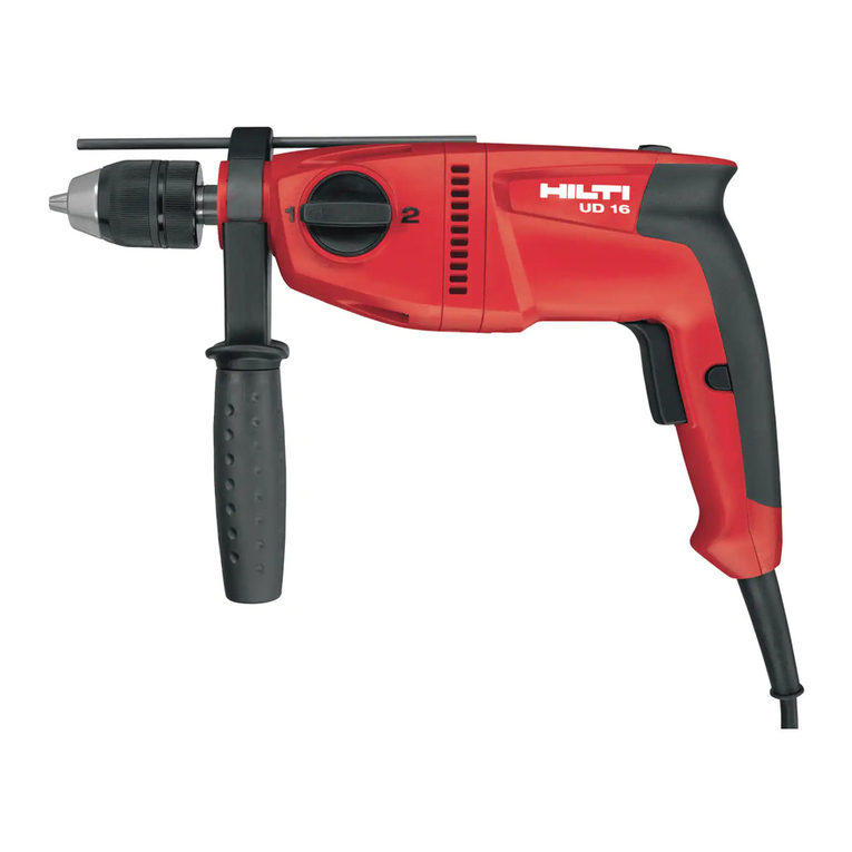
Hilti UH 650 User manual

BOperating instructions en
Mode d’emploi fr
Manual de instrucciones es
Manual de instruções pt
UH 650
Printed: 07.07.2013 | Doc-Nr: PUB / 5071287 / 000 / 00

This Product is Certified
Ce produit est homologué
Producto homologado por
Este produto está registrado
CUS
Printed: 07.07.2013 | Doc-Nr: PUB / 5071287 / 000 / 00

Printed: 07.07.2013 | Doc-Nr: PUB / 5071287 / 000 / 00

Printed: 07.07.2013 | Doc-Nr: PUB / 5071287 / 000 / 00

1
en
It is essential that the operating instructions
are read before the tool is operated for the
first time.
Always keep these operating instructions
together with the tool.
Ensure that the operating instructions are
with the tool when it is given to other
persons.
UH 650 hammer drill
1. General information
1.1 Safety notices and their meaning
-CAUTION-
Draws attention to apotentially dangerous situation that
could lead to minor personal injury or damage to the
equipment or other property.
-NOTE-
Draws attention to instructions and other useful infor-
mation.
1.2 Pictograms
Contents Page
1. General information 1
2. General safety rules 2
3. Specific safety rules and symbols 3
4. Functional description 4
5. Technical data5
6. Assembly 6
7. Operation 6
8. Care and maintenance 8
9. Tools and accessories 8
10. Troubleshooting 8
11. Disposal 9
12. Warranty 9
Operating controls and parts
Chuck (quick-release chuck or key-type
chuck with key)
Side handle with depth gauge
Function selector switch
2-speed gear selector switch
Forwards/reverse switch
On/off switch with electronic speed control
Lockbutton for sustained operation
Supply cord
These numbers refer to the corresponding illustra-
tions. The illustrations can be found on the fold-out cover
pages. Keep these pages open while studying the oper-
ating instructions.
In these operating instructions, the UH 650 is referred
to as " the tool ".
Location of identification data on the tool
The type designation can be found on the rating plate
and the serial number on the side of the motor housing.
Make anote of this datain your operating instructions
and always refer to it when making an enquiry to your
Hiltirepresentative or service department.
Type:
Serial No.:
Warning signs
Obligation signs
Wear ear
protection
Wear
protective
gloves
Wear
breathing
protection
Wear eye
protection
Read the
operating
instructions
before use.
Symbols
General
warning
Warning:
electricity
Warning:
hot surface
Wear a
hard hat
Printed: 07.07.2013 | Doc-Nr: PUB / 5071287 / 000 / 00

2
en
2. General safety rules
Avoid accidental starting. Be sure switch is off
before plugging in. Carrying tools with your finger
on the switch or plugging in tools that have the
switch on invites accidents.
Remove adjusting keys or wrenches before
turning the tool on. A wrench or akey that is left
attached to arotating part of the tool may result in
personal injury.
Do not overreach. Keep proper footing and balance
at all times. Proper footing and balance enables bet-
ter control of the tool in unexpected situations.
Use safety equipment. Always wear eye protection.
Dust mask, non-skid safety shoes, hard hat, or hearing
protection must be used for appropriate conditions.
5. Tool Use and Care
Use clamps or other practical way to secure and
support the workpiece to a stable platform. Holding
the work by hand or against your body is unstable
and may lead to loss of control.
Do not force tool. Use the correct tool for your
application. The correct tool will do the job better
and safer at the rate for which it is designed.
Do not use tool if the switch does not turn it on or
off. Any tool that cannot be controlled with the switch
is dangerous and must be repaired.
Disconnect the plug from the power source before
making any adjustments, changing accessories, or
storing the tool. Such preventive safety measures
reduce the risk of starting the tool accidentally.
Store idle tools out of reach of children and other
untrained persons. Tools are dangerous in the hands
of untrained users.
Maintain tools with care. Keep cutting tools sharp
and clean. Properly maintained tools with sharp cutting
edges are less likely to bind and are easier to control.
Check for misalignment or binding of moving parts,
breakage of parts and any other condition that may
affect the tools operation. If damaged, have the
tool serviced before using. Many accidents are
caused by poorly maintained tools.
Use only accessories that are recommended by the
manufacturer for your model. Accessories that may
be suitable for one tool may become hazardous when
used on another tool.
6. Service
Tool service must be performed only by qualified
repair personnel. Service or maintenance performed
by unqualified personnel could result in arisk of injury.
1. WARNING!
Read and understand all instructions.
Failure to follow all instructions listed below may
result in electric shock, fire and/or serious personal
injury. SAVE THESE INSTRUCTIONS
2. Work Area
Keep your work area clean and well lit. Cluttered
benches and dark areas invite accidents.
Do not operate power tools in explosive atmos-
pheres, such as in the presence of flammable
liquids, gases, or dust. Power tools create sparks
which may ignite the dust or fumes.
Keep bystanders, children and visitors away while
operating a power tool. Distractions can cause you
to lose control.
3. Electrical Safety
Double Insulated tools are equipped with a polarized
plug (one blade is wider than the other.) This plug
will fit in a polarized outlet only one way. If the plug
does not fit fully in the outlet, reverse the plug. If it
still does not fit, contact a qualified electrician to
install a polarized outlet. Do not change the plug in
any way. Double Insulation Zeliminates the need for
the three wire grounded power cord and grounded
power supply system.
Avoid body contact with grounded surfaces such as
pipes, radiators, ranges and refrigerators. There is
an increased risk of electric shock if your body is
grounded.
Don’t expose power tools to rain or wet conditions.
Water entering apower tool will increase the risk of
electric shock.
Do not abuse the cord. Never use the cord to carry
the tools or pull the plug from an outlet. Keep cord
away from heat, oil, sharp edges or moving parts.
Replace damaged cords immediately. Damaged
cords increase the risk of electric shock.
When operating a power tool outside, use an out-
door extension cord marked «W-A» or «W». These
cords are rated for outdoor use and reduce the risk of
electric shock.
4. Personal Safety
Stay alert, watch what you are doing and use com-
mon sense when operating a power tool. Do not
use tool while tired or under the influence of drugs,
alcohol, or medication. A moment of inattention
while operating power tools may result in serious
personal injury.
Dress properly. Do not wear loose clothing or
jewelry. Contain long hair. Keep your hair, clothing,
and gloves away from moving parts. Loose clothes,
jewelry, or long hair can be caught in moving parts.
Printed: 07.07.2013 | Doc-Nr: PUB / 5071287 / 000 / 00


3
en
3. Specific safety rules and symbols
Hold tools by insulated gripping surfaces when per-
forming an operation where the cutting tool may
contact hidden wiring or its own cord. Contact with a
“live” wire will make exposed metal parts of the tool
“live” and shock the operator.
Wear ear protectors when using the tool for extended
periods. Prolonged exposure to high intensity noise can
cause hearing loss.
Personal protective equipment
The user and any other persons in the vicinity must wear
suitable eye protection, asafety helmet, ear protection
and protective gloves. They must also wear breathing
protection if no dust removal system is used.
3.1 Basic information concerning safety
CAUTION: To avoid the risk of electric shock, injury or
fire, the basic safety precautions listed below must always
be observed when using electric tools.
In addition to the information relevant to safety given in
each of the sections of these operating instructions, the
following points must be strictly observed at all times.
3.2 Safety precautions at the workplace
●Ensure that the workplace is well ventilated.
●Keep the workplace tidy. Objects which could cause
injury should be removed from the working area.
Untidiness at the workplace can lead to accidents.
●Secure the working area(cordon off if necessary).
●Wear breathing protection if the work creates dust.
●It is recommended that protective gloves and non-slip
shoes are worn when working outdoors.
●Do not allow other persons to tamper with the tool or
the supply cord.
●Avoid unfavorable body positions. Work from asecure
stance and stay in balance at all times.
●Connect the dust removal system. If the tool is provided
with ameans of removing and collecting dust, check
that this is connected correctly and used as intended.
●To avoid tripping and falling when working, always
lead the supply cord, extension cord and dust extrac-
tion hose away to the rear.
●Concealed electric cables or gas and water pipes pre-
sent aserious hazard if damaged while you are work-
ing. Accordingly, check the areain which you are work-
ing beforehand (e.g. using ametal detector). External
metal parts of the tool may become live, for example,
when an electric cable is drilled into inadvertently.
3.3 General safety precautions
●Do not use the tool for purposes for which it was not
intended. Use the tool only as directed and when it is
in faultless condition.
●Avoid contact with rotating parts.
●Take the influences of the surrounding areainto account.
Do not expose the tool to rain or snow and do not use
it in damp or wet conditions.
●Keep the grips clean, dry and free from oil and grease.
●Do not use damaged insert tools.
●Use only insert tools designed for the application on
hand.
●The side handle must be fitted at all times when the
tool is in use.
●Check that the side handle is securely attached.
●Always hold the tool securely with both hands on the
grips provided.
●When not in use, the tool must be stored in adry place,
locked up or out of reach of children.
●Switch the tool off before transporting it.
●Take care of your insert tools. Observe the instruc-
tions concerning lubrication and changing insert tools.
●Check that moving parts function correctly without
sticking and that no parts are damaged. All parts must
be fitted correctly and fulfill all conditions necessary
for correct operation of the tool.
3.3.1 Mechanical hazards
●Observe the instructions concerning care and main-
tenance.
●Ensure that the insert tools used are equipped with
the appropriate connection end system and that they
are properly fitted and secured in the chuck.
●Wear protective gloves when handling sharp insert
tools in order to avoid cutting your hands or fingers.
When servicing a tool, use only identical replace-
ment parts. Follow instructions in the Maintenance
section of this manual. Use of unauthorized parts or
failure to follow Maintenance Instructions may create
arisk of electric shock or injury.
Printed: 07.07.2013 | Doc-Nr: PUB / 5071287 / 000 / 00

4
●Wear protective gloves when manipulating the side
handle and depth gauge in order to avoid injury (e.g.
pinching the fingers).
3.3.2 Electrical hazards
●Check the condition of the extension cord and replace
it if damage is found.
●Do not touch the supply cord in the event of it suffer-
ing damage while working. Disconnect the supply cord
plug from the socket.
●Damaged or faulty switches must be replaced at aHilti
service center.
●Have the tool repaired only by atrained electrical spe-
cialist (Hiltiservice center) using original Hiltispare
parts. Failure to observe this point may result in risk
of accident to the user.
●In the event of apower failure, switch the tool off and
unplug the supply cord.
●Avoid using extension cords with multiple sockets
and the simultaneous use of several tools connected
to one extension cord.
●Never operate the tool when it is dirty or wet. Dust
(especially dust from conductive materials) or damp-
ness adhering to the surface of the tool may, under
unfavorable conditions, present arisk of electric shock.
Dirty or dusty electric tools should thus be checked
at aHiltiservice center at regular intervals, especially
if used frequently for working on conductive materi-
als.
3.3.3 Thermal hazards
●The insert tool may become hot during use. Wear pro-
tective gloves when changing insert tools.
Warning:
hot surface
Wear
protective
gloves
Wear ear
protection
Wear
protective
gloves
Wear
breathing
protection
Wear eye
protection
Wear a
hard hat
Wear
breathing
protection
en
3.6 Symbols used on the tool
V volts
Wwatts
~alternating current
Hz hertz
Aamperes
n0no load speed
/min revolutions per minute
∅diameter
protective grounding
Zdouble insulated
4. Functional description
4.1 Use of the tool as intended
The tool is ahand-held, electric mains-powered ham-
mer drill for hammer drilling and rotary drilling.
The working environment may be on aconstruction site
of any kind and the tool may be used for renovation,
conversion or new building work.
The table below lists the tool's drilling diameter ranges
and possible applications:
The tool may be operated only when connected to a
power supply providing avoltage and frequency in com-
pliance with the information given on its rating plate.
Changes or modifications to the tool are not permissi-
ble.
The tool may be used only in adry environment.
Do not use the tool where there is arisk of fire or explo-
sion.
3.3.4 Dust
●Breathing protection must be worn when the tool is
used without adust removal system for work that cre-
ates dust.
●Working on materials containing asbestos is not per-
missible.
3.4 Requirements to be met by users
●The tool is intended for professional use.
●The tool may be operated, serviced and repaired only
by authorized, trained personnel. This personnel must
be informed of any special hazards that may be encoun-
tered.
3.5 Personal protective equipment
The user and any other persons in the vicinity must wear
suitable eye protection, ahard hat, ear protection and
protective gloves when the tool is in use. Breathing pro-
tection must be worn if no dust removal system is used.
Printed: 07.07.2013 | Doc-Nr: PUB / 5071287 / 000 / 00

5
en
Use only the insert tools and accessories listed for use
with the tool.
Observe the information printed in the operating instruc-
tions concerning operation, care and maintenance. The
tool and its ancillary equipment may present hazards
when used incorrectly or when used not as directed.
4.2 Chuck
–Quick-release chuck or
– Key-type chuck with key
4.3 Switches
– On/off switch with electronic speed control
– Lockbutton for sustained operation
– Function selector switch
– 2-speed gear selector switch
– Forwards/reverse switch
4.4 Grip
– Adjustable (pivoting) side handle with depth gauge
–Vibration-absorbing grip
Rotary drilling in metal
Rotary drilling in softwood
Rotary drilling in hardwood
Hammer drilling in masonry
Hammer drilling in stone
Drill bits with cylindrical shank, 1.5–13 mm dia.
(1/16″–1/2″)
Twist drills up to 30 mm dia.(11/8″)
Forstner drill bits up to 35 mm dia.(13/8″)
Hole saws up to 68 mm dia.(21/2″)
Twist drills up to 24 mm dia.(7/8″)
Forstner drill bits up to 25 mm dia.(1″)
Drill bits with cylindrical shanks, 3–16 mm dia.
(1/8″–5/8″)
Drill bits with cylindrical shanks, 3–8 mm dia.
(1/8″–3/8″)
4.5 Items supplied as standard
– The electric tool
–Side handle
– Depth gauge
– Dust shield
– Chuck (quick-release chuck or key-type chuck)
– Operating instructions
– Toolbox or cardboard box (depending on version)
See figure and the explanations of operating controls
and parts on page 1.
5. Technical data
Electric tool
Rated power input
Rated voltage
Rated current
Mains frequency
Weight of tool
UH 650
730 W
120 V
6.5 A
60 Hz
5.2 lbs (2.3 kg) with chuck and side handle
Dimensions (L xWxH)
Speed under no load
Hammering speed
Chuck
Max. torque
Speed control
Forwards/reverse
Double insulated
13 x 3 x 8 in (330 x 77 x 200 mm)
1st gear 1100 r.p.m.
2nd gear 3100 r.p.m.
48.000/min.
1/16"–1/2" (1.5–13 mm) dia.
1st gear 22 lb ft (30 Nm)
2nd gear 9 lb ft (12 Nm)
Electronic control switch (on/off switch)
Selector lever, interlock prevents switching when running
Protection class II Z
Right of technical changes reserved!
Printed: 07.07.2013 | Doc-Nr: PUB / 5071287 / 000 / 00

7.2.1 Quick-release chuck
-NOTE-
Unplug the supply cord from the mains socket.
Opening the quick-release chuck
-NOTE-
It may be necessary to rotate the chuck and spindle half
aturn until the automatic spindle lock engages.
1. Grip the chuck sleeve.
2. Turn the chuck sleeve away from "CLOSE" (the lock-
ing mechanism will first automatically release).
3. Keep turning the chuck sleeve until the insert tool is
released.
Opening the quick-release chuck when tightened exces-
sively
-NOTE-
It may be necessary to rotate the chuck and spindle half
aturn until the automatic spindle lock engages.
1. Grip the hexagonal section of the chuck securely with
a17 mm AF ring wrench or open end wrench.
2. Turn the chuck sleeve away from "CLOSE" (the lock-
ing mechanism will first automatically release).
3. Keep turning the chuck sleeve until the insert tool is
released.
Closing the quick-release chuck
-NOTE-
It may be necessary to rotate the chuck and spindle half
aturn until the automatic spindle lock engages.
1. Fit the insert tool into the chuck.
2. Tighten the chuck by turning the chuck sleeve firmly
toward "CLOSE".
3. After the jaws of the chuck make contact with the insert
tool, continue to turn the chuck sleeve firmly toward
"CLOSE" until the chuck locking mechanism engages
automatically (indicated by aclearly audible "click,
click").
6
en
6. Assembly
6.1 Fitting the side handle
1. Release the side handle clamping band by turning the
handle in acounter-clockwise direction.
2. Fit the side handle clamping band over the chuck and
onto the cylindrical section at the front end of the tool.
3. Pivot the side handle into the desired position.
4. Secure the side handle by turning the handle in aclock-
wise direction.
7. Operation
The mains voltage must correspond to the information
printed on the rating plate on the tool.
Never use the tool without the side handle.
Use avice or clamp to secure loose workpieces.
7.1 Preparing the tool for use
-NOTE-
Unplug the supply cord from the mains socket.
7.1.1 Adjusting the depth gauge
1. Release the side handle clamping mechanism by turn-
ing the handle in acounter-clockwise direction.
2. Pivot the side handle into the desired position.
3. Adjust the depth gauge to the desired drilling depth.
4. Tighten the side handle securely by turning the han-
dle in aclockwise direction.
7.2 Operation
-CAUTION-
●Drilling may cause splintering of
the material.
●Splinters may cause injury to parts
of the body and eyes.
●Wear eye protection, protective
gloves and breathing protection if
no dust removal system is used.
-CAUTION-
●The tool and the drilling operation
emit noise.
●Excessive noise may damage the
hearing.
●Wear ear protection.
Printed: 07.07.2013 | Doc-Nr: PUB / 5071287 / 000 / 00
7
en
7.2.2 Key-type chuck
-NOTE-
Use the chuck key supplied for opening and closing the
chuck.
Unplug the supply cord from the mains socket.
Opening the key-type chuck
1. Insert the chuck key in one of the three holes provided
on the chuck.
2. To open the chuck, turn the key counterclockwise.
3. Remove the insert tool from the chuck.
4. Remove the chuck key.
Closing the key-type chuck
1. Open the chuck sufficiently to allow the shaft of the
insert tool to be inserted.
2. Fit the insert tool into the chuck.
3. Close the jaws of the chuck by turning the toothed
ring until the jaws grip the insert tool.
4. Insert the chuck key in one of the three holes provided
on the chuck.
5. Secure the insert tool in the chuck by turning the chuck
key clockwise.
6. Remove the chuck key.
7.2.3 2-speed gear selector switch
-NOTE-
Change gear only when rotation has stopped.
The mechanical 2-speed gear selector switch can be
used to set the desired speed range:
1st gear = 0 – 1100 r.p.m.
2nd gear = 0 – 3100 r.p.m.
7.2.4 Rotary drilling
-NOTE-
The forwards/reverse switch must be set to the "R" posi-
tion.
1. Engage the function selector switch in the
position.
2. Adjust the side handle to the desired position and
check that it is fitted and secured correctly.
3. Plug the supply cord into the mains socket.
4. Position the tip of the drill bit at the point where the
hole is to be drilled.
5. Press the control switch (on/off switch) slowly. Begin
drilling at low speed, increasing speed only after the
drill bit has become centered in the hole.
6. Press the control switch (on/off switch) fully to con-
tinue drilling at full power.
7.2.5 Hammer drilling
-NOTE-
The forwards/reverse switch must be set to the "R" posi-
tion.
1. Engage the function selector switch in the posi-
tion.
2. Adjust the side handle to the desired position and
check that it is fitted and secured correctly.
3. Plug the supply cord into the mains socket.
4. Position the tip of the drill bit at the point where the
hole is to be drilled.
5. Press the control switch (on/off switch) slowly. Begin
drilling at low speed, increasing speed only after the
drill bit has become centered in the hole.
6. Press the control switch (on/off switch) fully to con-
tinue drilling at full power.
7. When drilling through-holes, avoid spalling by reduc-
ing drilling speed shortly before breaking through
(release the on/off switch slowly).
7.2.6 On/off switch with electronic speed control
The speed can be controlled by pressing the on/off switch
gradually until maximum speed is reached.
7.2.7 Lockbutton for sustained operation
The lockbutton is used to lock the on/off switch in the
"on" position: the motor then runs constantly (sustained
operating mode).
Activating sustained operating mode
1. Press the on/off switch and hold it in this position.
2. Press the lockbutton and hold it in this position.
3. Release the on/off switch.
4. Release the lockbutton.
Deactivating sustained operating mode
1. Press the on/off switch and then release it.
7.2.8 Forwards/reverse rotation
The forwards/reverse switch can be used to select the
desired direction of rotation.
-NOTE-
An interlock prevents switching between forwards/reverse
while the motor is running.
The forwards/reverse switch must be set to the "R" posi-
tion for hammer drilling and rotary drilling.
–Switch set to "R" = forwards rotation
position (R )
–Switch set to "L"
position = reverse rotation (L)
Printed: 07.07.2013 | Doc-Nr: PUB / 5071287 / 000 / 00
8
en
8. Care and maintenance
Unplug the supply cord from the mains socket.
8.1 Care of insert tools
Clean off dirt and dust deposits and protect your insert
tools from corrosion by wiping them with an oil-soaked
rag from time to time.
8.2 Changing the chuck
The quick-release chuck must be tightened to the spec-
ified torque of 40 Nm.
The key-type chuck must be tightened to the specified
torque of 40 Nm.
8.3 Care of the electric tool
The outer casing of the tool is made from impact-resis-
tant plastic. Sections of the grip are made from asyn-
thetic rubber material.
Never operate the tool when the ventilation slots are
blocked. Clean the ventilation slots carefully with adry
brush. Do not permit foreign objects to enter the inte-
rior of the tool. Clean the outside of the tool at regular
intervals with aslightly damp cloth. Do not use aspray,
steam pressure cleaning equipment or running water
for cleaning. This may negatively affect the electrical
safety of the tool. Always keep the grip surfaces of the
tool free from oil and grease. Do not use cleaning agents
containing silicone.
8.4 Maintenance
Check all external parts of the tool for damage at regu-
lar intervals and check that all controls operate fault-
lessly. Do not operate the tool if parts are damaged or
when the controls do not function faultlessly. If neces-
sary, your electric tool should be repaired at aHiltirepair
center.
Repairs to the electrical section of the tool may be car-
ried out only by trained electrical specialists.
8.5 Checks after care and maintenance
After carrying out care and maintenance on the tool,
check that all protective equipment has been refitted and
that all parts function faultlessly (side handle, chuck
tightened to specified torque).
10. Troubleshooting
Fault
The tool doesn't start.
No hammering action.
The tool does not achieve
full power.
The drill bit makes no
progress.
Possible cause
Fault in mains supply.
Supply cord or plug defective.
Control switch defective.
The function selector switch is set to
rotary drilling.
The extension cord is too long or has
inadequate cross section.
Control switch not fully pressed.
The forwards/reverse switch is set to
reverse rotation.
The drill bit is blunt or damaged.
Remedy
Plug in another electric appliance and
check whether it works.
Have the cord checked and, if necessary,
replaced by an electrical specialist.
Have it checked and, if necessary,
replaced by an electrical specialist.
Set the function selector switch to ham-
mer drilling.
Use ashorter extension cord or acord
with adequate cross section.
Press the control switch as far as it will
go.
Set the switch to forwards rotation.
Regrind the drill bit tip or replace the drill
bit.
9 Tools and accessories
Chuck
Chuck
UH 650
Quick-release chuck
Key-type chuck with key
Printed: 07.07.2013 | Doc-Nr: PUB / 5071287 / 000 / 00

9
en
11. Disposal
Most of the materials from which Hiltielectric tools are manufactured can be recycled. The materials must be cor-
rectly separated before they can be recycled. In many countries, Hiltihas already made arrangements for taking
back your old electric tools for recycling. Please ask your Hilticustomer service department or Hiltirepresenta-
tive for further information.
Should you wish to return the electric tool yourself to adisposal facility for recycling, proceed as follows: Dis-
mantle the electric tool as far as possible without the need for special tools. Use absorbent paper to wipe oily parts
clean and to collect any grease that runs out. This paper should also be disposed of correctly. On no account should
grease be allowed to enter the waste water system or to find its way into the ground.
The individual parts should be separated as follows:
Part/assembly Part/assembly Part/assembly
Toolbox PlasticPlastics recycling
Gear housing PlasticPlastics recycling
Bearing plate Aluminium Scrap metal
Grip, side handle PlasticPlastics recycling
Motor housing PlasticPlastics recycling
FanPlasticPlastics recycling
Motor (rotor and stator) Steel and copper Scrap metal
Supply cord Copper, synthetic rubber Scrap metal
Gearing parts Steel Scrap metal
Screws, small parts Steel Scrap metal
12. Warranty
Hiltiwarrants that the tool supplied is free of defects
in material and workmanship. This warranty is valid
so long as the tool is operated and handled correctly,
cleaned and serviced properly and in accordance with
the HiltiOperating Instructions, all warranty claims
are made within 12 months from the date of the sale
(invoice date), and the technical system is main-
tained. This means that only original Hilticonsum-
ables, components and spare parts may be used in
the tool. This warranty provides the free-of-charge
repair or replacement of defective parts only. Parts
requiring repair or replacement as aresult of normal
wear and tear are not covered by this warranty.
Under no circumstances will Hilti be obligated for
direct, indirect, incidental or consequential dam-
ages, losses or expenses in connection with, or by
reason of, the use of, or inability to use the tool for
any purpose. Hilti specifically excludes the implied
warranties of merchantability and fitness for a par-
ticular purpose.
For repair or replacement, send tool and/or related
parts immediately upon discovery of the defect to the
address of the local Hiltimarketing organization pro-
vided.
This constitutes Hilti’s entire obligation with regard to
warranty and supersedes all prior or contempo-
raneous comments and oral or written agreements
concerning warranties.
Printed: 07.07.2013 | Doc-Nr: PUB / 5071287 / 000 / 00

Printed: 07.07.2013 | Doc-Nr: PUB / 5071287 / 000 / 00

11
fr
Avant de mettre l'appareil en marche, lire
impérativement son mode d'emploi et bien
respecter les consignes.
Le présent mode d'emploi doit toujours
accompagner l'appareil.
Ne pas prêter ou céder l'appareil à un autre
utilisateur sans lui fournir le mode
d'emploi.
UH 650 Perceuse à percussion
1. Consignes générales
1.1 Termes signalant un danger
-ATTENTION-
Pour attirer l'attention sur une situation pouvant pré-
senter des dangers susceptibles d'entraîner des bles-
sures corporelles légères ou des dégâts matériels.
-REMARQUE-
Pour des conseils d'utilisation et autres informations
utiles.
Tables de matières Page
1. Consignes générales 11
3. Règles générales de sécurité12
3. Règles de sécuritéparticulières et symboles 13
4. Description du fonctionnement de l’appareil15
5. Caractéristiques techniques 15
6. Mise en service 16
7. Utilisation 16
8. Nettoyage et entretien 18
9. Outils et accessoires 18
10. Guide de dépannage 19
11. Recyclage 19
12. Garantie20
Organes de commande et éléments d'affichage
Mandrin de perçage (mandrin à serrage rapide
ou mandrin à clé)
Poignée latérale avec butée de profondeur
Sélecteur de fonction
Commutateur à 2 vitesses
Inverseur du sens de rotation droite / gauche
Interrupteur Marche / Arrêt avec variateur de
vitesse électronique
Bouton de blocage pour fonctionnement en
continu
Câble d'alimentation réseau
Les nombres renvoient respectivement aux illustra-
tions correspondant au texte et se trouvant sur les pages
rabattables. Pour lire le mode d'emploi, rabattre ces
pages de manière à voir les illustrations.
Dans le texte du présent mode d'emploi, le terme « appa-
reil»désigne toujours laperceuse à percussion UH 650.
Emplacement des détails d'identification sur l'appa-
reil
Ladésignation du modèle figure sur laplaque signalé-
tique et le numéro de série sur le côtédu carter moteur.
Inscrire ces renseignements dans le mode d'emploiet
toujours s'y référer pour communiquer avec notre repré-
sentant ou agence Hilti.
Type :
N° de série :
1.2 Pictogrammes
Symboles d'avertissement
Symboles d'obligation
Porter un
casque
antibruit
Porter des
gants de
protection
Porter un
masque
respiratoire
léger
Porter des
lunettes de
protection
Lire le mode
d'emploi
avant d'utiliser
l'appareil
Symboles
Avertissement
danger
général
Avertissement tension
électrique dangereuse
Avertissement
surfaces chaudes
Porter un
casque de
protection
Printed: 07.07.2013 | Doc-Nr: PUB / 5071287 / 000 / 00

12
fr
2. Règles générales de sécurité
1. Avertissement!
Vous devez lire et comprendre toutes les instructions.
Le non-respect, même partiel, des instructions ci-
après entraîne un risque de choc électrique, d’incen-
die et/ou de blessures graves.
CONSERVEZ CES INSTRUCTIONS!
2. Aire de travail
Veillez à ce que l’aire de travail soit propre et bien
éclairée. Le désordre et le manque de lumière favori-
sent les accidents.
N’utilisez pas d’outils électriques dans une atmos-
phère explosive, par exemple en présence de
liquides, de gaz ou de poussières inflammables.
Les outils électriques créent des étincelles quipour-
raient enflammer les poussières ou les vapeurs.
Tenez à distance les curieux, les enfants et les visi-
teurs pendant que vous travaillez avec un outil
électrique. Ils pourraient vous distraire et vous faire
faire une fausse manoeuvre.
3. Sécurité électrique
Les outils à double isolation sont équipés d’une
fiche polarisée (une des lames est plus large que
l’autre), qui ne peut se brancher que d’une seule
façon dans une prise polarisée. Si la fiche n’entre
pas parfaitement dans la prise, inversez sa posi-
tion; si elle n’entre toujours pas bien, demandez à
un électricien qualifié d’installer une prise de cou-
rant polarisée. Ne modifiez pas la fiche de l’outil.
Ladouble isolation Zélimine le besoin d’un cordon
d’alimentation à trois fils avec mise à laterre ainsi
que d’une prise de courant mise à laterre.
Évitez tout contact corporel avec des surfaces mises
à la terre (tuyauteries, radiateurs, cuisinières, réfri-
gérateurs, etc.). Le risque de choc électrique est plus
grand sivotre corps est en contact avec laterre.
N’exposez pas les outils électriques à la pluie ou à
l’eau. Laprésence d’eau dans un outil électrique
augmente le risque de choc électrique.
Ne maltraitez pas le cordon. Ne transportez pas
l’outil par son cordon et ne débranchez pas la fiche
en tirant sur le cordon. N’exposez pas le cordon à
la chaleur, à des huiles, à des arêtes vives ou à des
pièces en mouvement. Remplacez immédiatement
un cordon endommagé. Un cordon endommagé
augmente le risque de choc électrique.
Lorsque vous utilisez un outil électrique à l’extérieur,
employez un prolongateur pour l’extérieur marqué
«W-A» ou «W». Ces cordons sont faits pour être utilisés
à l’extérieur et réduisent le risque de choc électrique.
4. Sécurité des personnes
Restez alerte, concentrez-vous sur votre travail et
faites preuve de jugement. N’utilisez pas un outil
électrique si vous êtes fatigué ou sous l’influence de
drogues, d’alcool ou de médicaments. Un instant
d’inattention suffit pour entraîner des blessures graves.
Habillez-vous convenablement. Ne portez ni vête-
ments flottants ni bijoux. Confinez les cheveux
longs. N’approchez jamais les cheveux, les vête-
ments ou les gants des pièces en mouvement. Des
vêtements flottants, des bijoux ou des cheveux longs
risquent d’être happés par des pièces en mouvement.
Evitez tout démarrage involontaire. Avant de bran-
cher l’appareil, vérifiez que l’interrupteur est bien
en position arrêt. Ne portez pas d’appareil en ayant
le doigt placésur l’interrupteur et ne branchez pas
l’appareil avec l’interrupteur en position «marche»
(risques d’accidents).
Enlevez les clés de réglage ou de serrage avant de
démarrer l’outil. Une clélaissée dans une pièce tour-
nante de l’outil peut provoquer des blessures.
Ne vous penchez pas trop en avant. Maintenez un
bon appui et restez en équilibre en tout temps. Une
bonne stabilitévous permet de mieux réagir à une
situation inattendue.
Utilisez des accessoires de sécurité. Portez tou-
jours des lunettes ou une visière. Selon les condi-
tions, portez aussiun masque antipoussière, des
bottes de sécuritéantidérapantes, un casque protec-
teur et/ou un appareil antibruit.
5. Utilisation et entretien des outils
Immobilisez le matériau sur une surface stable au
moyen de brides ou de toute autre façon adéquate.
Le fait de tenir lapièce avec lamain ou contre votre
corps offre une stabilitéinsuffisante et peut amener
un dérapage de l’outil.
Ne forcez pas l’outil. Utilisez l’outil approprié à la
tâche. L’outil correct fonctionne mieux et de façon
plus sécuritaire. Respectez aussilavitesse de travail
quiluiest propre.
N’utilisez pas un outil si son interrupteur est blo-
qué. Un outil que vous ne pouvez pas commander
par son interrupteur est dangereux et doit être réparé.
Débranchez la fiche de l’outil avant d’effectuer un
réglage, de changer d’accessoire ou de ranger
l’outil. De telles mesures préventives de sécurité
réduisent le risque de démarrage accidentel de l’outil.
Rangez les outils hors de la portée des enfants et
d’autres personnes inexpérimentées. Les outils
sont dangereux dans les mains d’utilisateurs novices.
Prenez soin de bien entretenir les outils. Les outils
de coupe doivent être toujours bien affûtés et
Printed: 07.07.2013 | Doc-Nr: PUB / 5071287 / 000 / 00

13
fr
3. Règles de sécurité particulières et symbols
Tenez l’outil par ses surfaces de prise isolées pendant
toute opération où l’outil de coupe pourrait venir en
contact avec un câblage dissimulé ou avec son propre
cordon. En cas de contact avec un conducteur sous ten-
sion, les pièces métalliques à découvert de l’outil trans-
mettraient un choc électrique à l’utilisateur.
Portez un appareil antibruit si vous devez utiliser l’ou-
til pendant une période prolongée.
Une exposition prolongée à un bruit de forte intensité
peut entraîner des lésions de l’ouie.
3.1 Consignes de sécurité générales
Attention : Lors de l'utilisation d'appareils électriques,
il est impératif de respecter les mesures de sécuritéfon-
damentales afin d'éviter les électrocutions, les risques
de blessures et d'incendies.
En plus des consignes de sécuritéfigurant aux différents
chapitres du présent mode d'emploi, il importe de tou-
jours bien respecter les directives suivantes.
3.2 Aménagement correct du poste de travail
●Veiller à ce que l'espace de travail soit bien ventilé.
●Laisser le poste de travail en ordre. Débarrasser le
poste de travail de tous objets susceptibles de vous
blesser. Un désordre sur le lieu de travail peut provo-
quer des accidents.
●Sécuriser le poste de travail.
●Porter un masque respiratoire sile travail exécutépro-
duit de lapoussière.
●Pour les travaux à l'extérieur, des gants de protection
et des chaussures à semelle antidérapante sont recom-
mandés.
●Ne laisser personne toucher l'appareil ou le câble de
rallonge.
●Eviter toute posture anormale du corps. Veiller à tou-
jours rester stable et à garder l'équilibre.
●Raccorder le dispositif externe d'aspiration de pous-
sières. Lorsque les dispositifs externes d'aspiration
et de récupération de poussières sont montés, s'as-
surer qu'ils sont raccordés et utilisés correctement.
●Pour éviter tout risque de chute, toujours tenir le câble
d'alimentation réseau et de rallonge à l'arrière de l'ap-
pareil.
●Tous les câbles ou gaines électriques, conduites de
gaz ou d'eau cachés représentent un risque sérieux
s'ils viennent à être endommagés pendant le travail.
Il est par conséquent recommandéd'inspecter au
préalable lazone de travail, par ex. à l'aide d'un détec-
teur de métaux. Toutes les pièces métalliques exté-
rieures de l'appareil peuvent devenir conductrices,
par exemple, lorsqu'un câble électrique est endom-
magépar inadvertance.
3.3 Consignes de sécurité générales
●Ne pas utiliser l'appareil à des fins non prévues, mais
seulement conformément aux spécifications et dans
un excellent état.
●Eviter de toucher des pièces en rotation.
●Prêter attention aux influences environnementales de
l'espace de travail. Protéger l'appareil des intempé-
ries, ne pas l'utiliser dans un environnement humide
ou mouillé.
●Essuyer les poignées afin d'éliminer toutes traces
d'humiditéet enlever toutes traces de graisse ou d'huile.
●Ne pas utiliser d'outils endommagés.
●Utiliser uniquement des outils appropriés à l'usage.
●Lapoignée latérale doit être montée pour tous les tra-
vaux.
●S'assurer que lapoignée latérale est fixée en toute
sécurité.
●Toujours tenir l'appareil des deux mains par les poi-
gnées prévues à cet effet.
propres. Des outils bien entretenus, dont les arêtes
sont bien tranchantes, sont moins susceptibles de
coincer et plus faciles à diriger.
Soyez attentif à tout désalignement ou coincement
des pièces en mouvement, à tout bris ou à toute
autre condition préjudiciable au bon fonctionne-
ment de l’outil. Si vous constatez qu’un outil est
endommagé, faites-le réparer avant de vous en
servir. De nombreux accidents sont causés par des
outils en mauvais état.
N’utilisez que des accessoires que le fabricant
recommande pour votre modèle d’outil. Certains
accessoires peuvent convenir à un outil, mais être
dangereux avec un autre.
6. Réparation
La réparation des outils électriques doit être
confiée à un réparateur qualifié. L’entretien ou la
réparation d’un outil électrique par un amateur peut
avoir des conséquences graves.
Pour la réparation d’un outil, n’employez que des
pièces de rechange d’origine. Suivez les directives
données à la section «Réparation» de ce manuel.
L’emploide pièces non autorisées ou le non-respect
des instructions d’entretien peut créer un risque de
choc électrique ou de blessures.
Printed: 07.07.2013 | Doc-Nr: PUB / 5071287 / 000 / 00

14
●Conserver les appareils non utilisés en toute sécurité.
Tous les appareils non utilisés doivent être rangés
dans un endroit sec, en hauteur ou ferméà clé, hors
de portée des enfants.
●Mettre l'appareil hors tension pour le transport.
●Entretenir les outils soigneusement. Observer les ins-
tructions concernant lalubrification et le changement
d'outil.
●Vérifier que toutes les pièces mobiles fonctionnent
parfaitement et ne coincent pas, et que les pièces ne
sont pas abîmées. Toutes les pièces doivent être mon-
tées correctement et remplir toutes les conditions
propres à garantir le parfait fonctionnement de l'appareil.
3.3.1 Risques mécaniques
●Bien respecter les instructions relatives au nettoyage
et à l'entretien de l'appareil.
●Vérifier que les outils sont bien munis du système
d'emmanchement adaptéà l'appareil et qu'ils sont
toujours correctement fixés dans le mandrin.
●Se protéger des blessures par coupure en portant des
gants de protection lors de lamanipulation d'outils
affûtés.
●Se protéger des blessures par écrasement en portant
des gants de protection lors de lamanipulation de la
poignée latérale et de labutée de profondeur.
3.3.2 Risques électriques
●Contrôler régulièrement les câbles de rallonge et les
remplacer s'ils sont endommagés.
●Sile câble d'alimentation réseau ou de rallonge est
endommagépendant le travail, ne pas le toucher.
Débrancher laprise.
●Les interrupteurs endommagés doivent être rempla-
cés par le S.A.V. Hilti.
●Seul un électricien (S.A.V. Hilti) est habilitéà réparer
l'appareil, afin que des pièces de remplacement d'ori-
gine soient utilisées. Sinon, des risques d'accident
peuvent survenir pour l'utilisateur.
●Lors d'une coupure de courant : mettre l'appareil sur
arrêt, débrancher lafiche.
●Les câbles de raccordement avec prises multiples et
le fonctionnement simultanéde plusieurs appareils
doivent être évités.
●Ne jamais faire fonctionner l'appareil s'il est encrassé
ou mouillé.Lapoussière accumulée sur les faces de
l'appareil, en particulier celle produite par des matériaux
conducteurs, ou l'humiditérisquent, dans des condi-
tions défavorables, de provoquer une décharge élec-
trique. C'est pourquoiil convient de faire réviser les appa-
reils encrassés par le S.A.V. Hiltià intervalles réguliers,
surtout s'ils sont utilisés sur des matériaux conducteurs.
3.3.3 Risques thermiques
●L'appareil peut être très chaud après utilisation. Se
munir de gants de protection pour changer l'outil.
3.3.4 Poussières
●Sil'appareil fonctionne sans dispositif d'aspiration de
lapoussière et sile travail effectuédégage de lapous-
sière, porter un masque respiratoire léger.
●Ne pas travailler sur des matériaux contenant de
l'amiante.
3.4 Exigences vis-à-vis de l'utilisateur
●L'appareil est destinéà des utilisateurs professionnels.
●L'appareil ne doit être utilisé, entretenu et réparéque
par un personnel agréé et forméà cet effet. Ce per-
sonnel doit être au courant des dangers inhérents à
l'utilisation de l'appareil.
3.5 Equipement de protection individuel
L'utilisateur et les personnes se trouvant à proximité
pendant l'utilisation de l'appareil doivent porter des
lunettes de protection adaptées, un casque de protec-
tion, un casque antibruit, des gants de protection et,
lorsqu'ils n'utilisent pas de dispositif d'aspiration de la
poussière, un masque respiratoire léger.
Porter un
casque
antibruit
Porter des
gants de
protection
Porter un
masque
respiratoire
léger
Porter des
lunettes de
protection
Porter un
casque de
protection
Porter un
masque
respiratoire
léger
fr
Porter des
gants de
protection
Avertissement
surfaces
chaudes
3.6 Symboles utilisés sur l’appareil:
V Volts /min tours par minute
WWatts ∅diamètre
~ courant alternatifmise à la terre de
Hz Hertz protection
A Ampères Zdouble isolation
n0vitesse à vide
Printed: 07.07.2013 | Doc-Nr: PUB / 5071287 / 000 / 00
15
fr
4. Description du fonctionnement de l'appareil
4.1 Utilisation conforme à l'usage prévu
L'appareil est une perceuse à percussion guidée à lamain
et alimentée par une tension de secteur pour le perçage
à percussion et le perçage rotatif. L'environnement de tra-
vail peut être des chantiers de tout type tels que des
constructions nouvelles, des extensions, des transfor-
mations ou de larénovation. Le tableau ci-dessous indique
Utiliser uniquement des outils et des pièces d'accessoire prévus d'ori-
gine. Bien respecter les consignes concernant l'utilisation, le net-
toyage et l'entretien de l'appareil quifigurent dans le présent mode
d'emploi. L'appareil et ses accessoires peuvent s'avérer dangereux
s'ils sont utilisés de manière incorrecte par du personnel non quali-
fié ou de manière non conforme à l'usage prévu.
4.2 Mandrin
–Mandrin à serrage rapide ou
–Mandrin à clé
4.3 Interrupteur
– Interrupteur de commande avec variateur de vitesse électronique
– Bouton de blocage pour fonctionnement en continu
–Sélecteur de fonction
– Commutateur à 2 vitesses
– Inverseur du sens de rotation droite/gauche
Perçage rotatif dans le métal
Perçage rotatif dans le bois tendre
Perçage rotatifdans le bois dur
Perçage à percussion dans labrique
Perçage à percussion dans lapierre
Queue cylindrique de lamèche ∅1,5 – 13 mm
(1/16″jusqu'à 1/2″)
Mèche hélicoïdale jusqu'à ∅30 mm (11/8″)
Mèche à pointe de centrage jusqu'à ∅35 mm (13/8″)
Scie à cloche jusqu'à ∅68 mm (21/2″)
Mèche hélicoïdale jusqu'à ∅24 mm (7/8″)
Mèche à pointe de centrage jusqu'à ∅25 mm (1″)
Queue cylindrique de lamèche ∅3 – 16 mm
(1/8″jusqu'à 5/8″)
Queue cylindrique de lamèche ∅3 – 8 mm
(1/8″jusqu'à 3/8″)
laplage de puissance des utilisations possibles : Il doit
uniquement être mis en fonctionnement avec une tension
et une fréquence réseau conformes aux indications de la
plaque signalétique. Toute manipulation ou modification
de l'appareil est interdite. L'appareil doit uniquement être
utilisédans un environnement sec. Ainsique dans des
endroits présentant un danger d'incendie ou d'explosion.
4.4 Poignées
–Poignée latérale orientable avec butée de profondeur
–Poignée anti-vibration
4.5 L'équipement standard livré comprend
– Appareil
–Poignée latérale
– Butée de profondeur
– Ecran anti-poussière
–Mandrin de perçage (mandrin à serrage rapide ou mandrin à clé)
– Mode d'emploi
– Coffret de transport ou emballage carton (selon le mode de livraison)
Voir figure ainsique ladescription des principaux éléments de
l’appareil et des autres éléments, page 11.
5. Caractéristiques techniques
Appareil
Puissance absorbée nominale
Tension nominale
Courant nominal
Fréquence réseau
Poids de l'appareil
UH 650
730 W
120 V
6,5 A
60 Hz
5,2 lbs (2,3 kg) avec le mandrin de perçage et lapoignée latérale
Dimensions (L x l x h)
Vitesse de rotation à vide :
Cadence de percussion
Mandrin
Couple max. prescrit
Variation de vitesse
Sens de rotation gauche/droite
Isolation
13 x 3 x 8 in (330 x 77 x 200 mm)
1. Vitesse 1100 tr/min
2. Vitesse 3100 tr/min
48'000/min.
∅1/16"–1/2" (1,5–13 mm)
1. Vitesse 22 lb ft (30 Nm)
2. Vitesse 9 lb ft (12 Nm)
Electronique par variateur électronique de vitesse (interrupteur Marche / Arrêt)
Inverseur avec blocage pendant lamarche
Classe de protection II Z
Sous réserve de modifications techniques!
Printed: 07.07.2013 | Doc-Nr: PUB / 5071287 / 000 / 00

7.2.1 Mandrin à serrage rapide
-REMARQUE-
Débrancher laprise.
Ouverture du mandrin à serrage rapide
-REMARQUE-
Le cas échéant, le mandrin et labroche doivent être tour-
nés d'un demi-tour, afin que l'arrêt de labroche s'en-
cliquète.
1. Saisir ladouille.
2. Tourner ladouille dans le sens inverse de "FERME".
(Dans un premier temps, le verrouillage automatique
est débloqué)
3. Tourner ladouille jusqu'à ce que l'outil se libère.
Ouverture du mandrin à serrage rapide en cas de ten-
sion élevée
-REMARQUE-
Le cas échéant, le mandrin et labroche doivent être tour-
nés d'un demi-tour, afin que l'arrêt de labroche s'en-
cliquète.
1. Maintenir fermement le mandrin en appliquant une
clépolygonale ou une cléà fourche SW 17 sur lapar-
tie hexagonale de celui-ci.
2. Tourner ladouille dans le sens inverse "FERME". (Dans
un premier temps, le verrouillage automatique est
débloqué)
3. Tourner ladouille jusqu'à ce que l'outil se libère.
16
fr
6. Mise en service
6.1 Montage de la poignée latérale
1. Ouvrir le dispositif de serrage de lapoignée latérale
en tournant lapoignée dans le sens contraire des
aiguilles d'une montre.
2. Faire glisser lapoignée latérale (collier de fixation) au-
dessus du porte-outil dans le mandrin.
3. Tourner lapoignée latérale dans laposition souhai-
tée.
4. Fixer lapoignée latérale en latournant par lapoignée
dans le sens des aiguilles d'une montre.
7. Utilisation
Latension du secteur doit correspondre à celle indiquée
sur laplaquette signalétique.
Toujours porter l'appareil par lapoignée latérale.
Pour bloquer les pièces, utiliser un dispositif de serrage
ou un étau.
7.1 Préparation de l'appareil avant utilisation
-REMARQUE-
Débrancher la prise.
7.1.1 Réglage de la butée de profondeur
1. Ouvrir le dispositif de serrage de lapoignée latérale
en tournant lapoignée.
2. Tourner lapoignée latérale dans laposition souhai-
tée.
3. Régler labutée de profondeur sur laprofondeur de
perçage souhaitée.
4. Serrer lapoignée latérale à fond en tournant lapoi-
gnée.
7.2 Fonctionnement
-ATTENTION-
●Il y arisque de projection d'éclats
de matériau durant le perçage.
●Les éclats de matériau peuvent
entraîner des blessures corporelles
et aux yeux.
●Porter des lunettes, des gants de
protection et siaucun aspirateur de
poussière n'est utilisé, porter un
masque respiratoire léger.
-ATTENTION-
●L'appareil et l'opération de perçage
sont bruyants.
●Un bruit trop fort risque de
provoquer des lésions auditives.
●Porter un casque antibruit.
Printed: 07.07.2013 | Doc-Nr: PUB / 5071287 / 000 / 00

Other manuals for UH 650
2
Table of contents
Languages:
Other Hilti Drill manuals

Hilti
Hilti SFE 2-A12 User manual

Hilti
Hilti SFH 14-A User manual

Hilti
Hilti TE 4-A22 User manual

Hilti
Hilti SF 10W-A22 User manual

Hilti
Hilti TE 2-A22 User manual

Hilti
Hilti DD 110-W User manual

Hilti
Hilti SF 6-A22 User manual

Hilti
Hilti UH 700 User manual

Hilti
Hilti SF180-A User manual

Hilti
Hilti SF 8M-A22 User manual

Hilti
Hilti NURON CD 4 22 User manual

Hilti
Hilti DD EC-1 User manual

Hilti
Hilti TE 6-A36 User manual

Hilti
Hilti SF 22-A User manual

Hilti
Hilti NBL 4-22 User manual

Hilti
Hilti SIW 22T-A 1/2 inch User manual

Hilti
Hilti TE 40 User manual

Hilti
Hilti DD 30-W User manual

Hilti
Hilti UD16 User manual

Hilti
Hilti NURON SBT 6-22 User manual