3
5
4
1
2
5
6
7
6
Use of the equipment as directed
■The DS-WS10(-E) wire saw has been designed for
the te hni al demolition of steel, on rete, stone or
bri kwork stru tures in onstru tion and ivil engi-
neering appli ations. Use of the saw for other appli-
ations is onsidered to be “not as dire ted” and
requires prior approval by the manufa turer.
■The operator in harge must be aware of the possi-
ble dangers and of his responsibility for safety, both
with regard to himself and to others. The operator is
responsible for se uring the danger area by ordon-
ing the area off and installing the appropriate pro-
te tive equipment.
■The wire saw is designed for a maximum utting
length of 2 meters. The maximum distan e between
the pivoting pulleys at the ma hine and the wire entry
or exit point must not ex eed 3.5 meters.
■The wire saw may be operated only by spe ialists
trained in on rete utting te hniques, referred to in
the following as “operators”. These persons must be
familiar with the ontent of these operating instru -
tions and must have been trained in their safe appli-
ation by a Hilti spe ialist.
■National regulations and legislation as well as the
information in the operating instru tions and safety
pre autions on erning the saw and its a essories
(sawing wire, fastening a essories, lifting equip-
ment, ompressor, hydrauli power unit et .) must
be observed.
■Do not use the saw to ut loose obje ts or obje ts
held against the wire by hand.
■Use of the wire saw or its omponents for purposes
other than wire sawing is prohibited, i.e. use as a
transport or onveyan e devi e is not permissible.
■The ma hine is suitable for wet and dry utting. A
va uum dust removal system must be used when
dry wire sawing. Spe ial dust removal hoods are
available on request.
■The equipment may be lifted by rane only at the lift-
ing points provided.
■Do not ut materials whi h, as a result of the utting
pro ess, may produ e toxi , hazardous or explosive
dust or vapors.
■Do not ut easily ombustible aluminum or magne-
sium alloys.
2.1
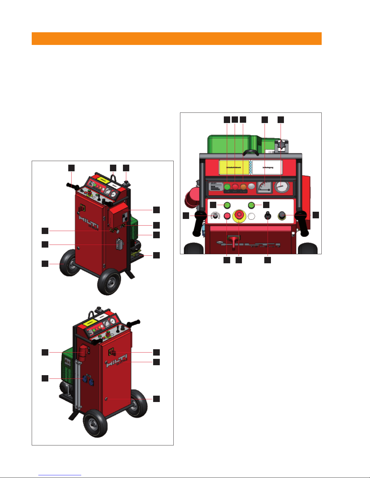
2. Description
Components
2.2
Base plate
Guide rail and advan e unit
Pivoting pulley rossbar
Hydrauli drive unit (DS WS10) or ele tri drive unit
(DS WS10-E)
Guard
Wire storage extension
End stop
Printed: 08.07.2013 | Doc-Nr: PUB / 5069736 / 000 / 01