Hindley Electronics 105295-HEI User manual

Installation Instructions for:
105295-HEI Kit
Gen1 to Gen5
Control System
P/N 105294-HEI Rev.0 HEI 1/ 16

Installation Instructions for:
105295-HEI Kit
Gen1 to Gen5
Control System
Table of Contents
Models Affected.........................................................................................................................................................3
Required to Perform Procedure:...............................................................................................................................3
Suitability for Application...........................................................................................................................................3
Installation Procedures .......................................................................................................4
Changing the Software Configuration......................................................................................................................7
Machine Configurations.............................................................................................................................................8
Configuration Code Chart and Machine Option Definitions for GS-1530, GS-1532, GS-1930, and GS-932 Models
...................................................................................................................................................................................9
How to Activate the Battery Drain Alarm Option ......................................................................................................9
Configuration Code Chart GS-2032/2632 and GS-2046/2646/3246 Models........................................................10
Configuration Code Chart GS-2032/2632 and GS-2046/2646/3246 Models..........................................................11
How to Activate the Battery Drain Alarm Option .....................................................................................................11
Configuration Code Chart and Machine Option Definitions ...................................................................................12
Speed Tuning.....................................................................................................................................................13
How to Adjust the Lift Speed...................................................................................................................................13
How to Adjust the ...................................................................................................................................................14
Stowed Drive Speed................................................................................................................................................14
How to Adjust the ...................................................................................................................................................15
Raised Drive Speed................................................................................................................................................15
How to Adjust the ...................................................................................................................................................16
Slow Drive Speed – GR Models..............................................................................................................................16
P/N 105294-HEI Rev.0 HEI 2/ 16

Installation Instructions for:
105295-HEI Kit
Gen1 to Gen5
Control System
Models Affected
This instruction describes how to install the
100839-HEI on the following Genie machines only:
GS-1530/1532/1930/1932 (before S.N. 75000)
GS-2032/2632 (before S.N. 75000)
GS-2046/2646/3246 (before S.N. 75000)
GR-12/15/20 (after GR05-4999)
Important:
The procedure outlined in these instructions may only
be performed by personnel who can identify risks and
potential hazards and have been qualified to work with
the specific equipment concerned.
Read this entire procedure before beginning. Follow
instructions when performing the procedure. Shortcuts
may cause expose you and others to potentially
dangerous conditions.
Required to Perform Procedure:
#2 Slotted screwdriver
11/32 inch combination wrenches
7/16 inch combination wrenches
Dielectric grease
Suitability for Application
The end-user alone knows the specific needs of their
application. Therefore, the end-user of this product is
responsible to make decisions regarding the suitability
of use with regard to their intended application. The
customer is also responsible to ensure that products
installed will conform to all applicable laws and
regulations established by nation, state, locality, and
regulating body.
Trademarks
The Genie brand name and model numbers are
copyrighted by and trademarks of the Terex
Corporation.
P/N 105294-HEI Rev.0 HEI 3/ 16

Installation Instructions for:
105295-HEI Kit
Gen1 to Gen5
Control System
INSTALLATION PROCEDURES
Components of Kits 105289 and
105290:
Screw – HHC, 1/4-20 x x0.75 inch
P/N Z0186 Qty. 4
Washer – Lock ¼ inch
P/N Z0188 Qty. 4
Controls - Platform, Gen 5
P/N 100840-HEI Qty.1
Mount – Platform Controls
P/N 105990 Qty.1
Bumper – Rubber
P/N 43392 Qty.2
Screw – RHM, 8-32 x 0.5 inch
P/N Z075 Qty.1
Washer – Flat, #8
P/N 90126A512 Qty.1
Nut – Nylock, 8-32
P/N 90675A009 Qty. 1
Procedure
1. Tag and disconnect the platform controls wire
harness from the control cable at the platform main
deck.
2. Models with foot switch: Tag and disconnect the
platform controls wire harness from the foot switch.
Models with security latch:
3. Release the latch and remove the platform controls
from the machine.
4. Remove the catch bracket, used to secure the
platform controls to the platform, from the side of
the platform controls mount bracket. Set the catch
to the side. Discard the fasteners.
5. Using the provided 8-32 screw, washer and nut
(P/N Z075, 90126A512, and 90675A009). Install the
catch bracket, removed in step 4 onto the provided
platform controls mount (P/N 105990) in
approximately the same location it was installed
previously. Securely tighten the fasteners. Do not
over tighten.
6. Remove and discard the three joystick mount
buttons from the platform railing.
All models:
7. Using the provided 1/40-20 fasteners (P/N Z0186
and Z0188), install the provided platform controls
(P/N 100840-HEI) onto the mount from step 5.
8. If required and working from the inside of the
platform, install the provided rubber bumpers (P/N
43392) in to the two holes in the platform support on
the railing.
Install the platform controls onto the platform railing.
Secure the latch on to the catch bracket (if equipped).
9. Using dielectric grease in the connectors, securely
connect the platform controls wire harness to the
control cable at the platform main deck.
10. Models with foot switch: Using dielectric grease
in the connectors, securely connect the platform
controls wire harness to the foot switch.
P/N 105294-HEI Rev.0 HEI 4/ 16

Installation Instructions for:
105295-HEI Kit
Gen1 to Gen5
Control System
Components of Kits 105291 and
105293:
Screw – HHC, 1/4-20 x 0.75 inch
P/N Z0186 Qty.4
Washer – Lock, ¼ inch
P/N Z0188 Qty.4
Controls - Platform, Gen 5
P/N 100840-HEI Qty.1
Mount – Platform Controls
P/N 105990 Qty.1
P
ROCEDURES
Procedure
1. Tag and disconnect the platform controls wire
harness from the control cable at the platform main
deck.
2. Models with foot switch: Tag and disconnect the
platform controls wire harness from the foot switch.
3. Remove the platform controls from the machine.
4. Using the provided 1/4-20 fasteners (P/N Z0186
and Z0188), install the provided platform controls
( P/N 100840-HEI) onto the provided platform
controls mount (P/N 105990).
5. Install the platform controls onto the platform railing.
6. Using dielectric grease in the connectors, securely
connect the platform controls wire harness to the
control cable at the platform main deck.
7. Models with foot switch: Using dielectric grease
in the connectors, securely connect the platform
controls wire harness to the foot switch.
P/N 105294-HEI Rev.0 HEI 5/ 16

Installation Instructions for:
105295-HEI Kit
Gen1 to Gen5
Control System
P
ROCEDURES
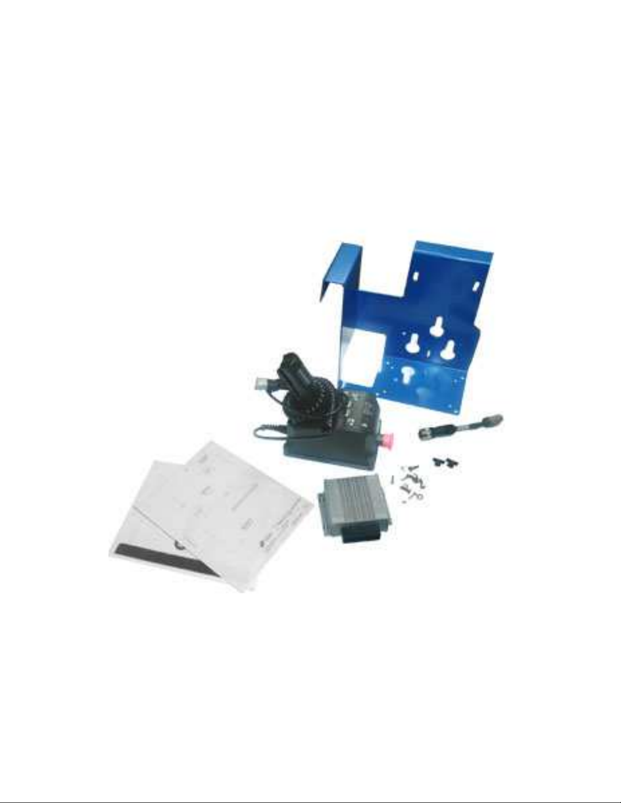
Components of Kit 105295:
Kit – ECM, Gen 5
P/N 100839-HEI Qty. 1
Screw – HHC, 1/4-20 x x0.75 inch
P/N Z0186 Qty. 4
Washer – Lock ¼ inch
P/N Z0188 Qty. 4
Controls - Platform, Gen 5
P/N 100840-HEI Qty.1
Mount – Platform Controls
P/N 105990 Qty.1
Screw – RHM, 8-32 x 0.5 inch
P/N Z075 Qty.1
Washer – Flat, #8
P/N 90126A512 Qty.1
Nut – Nylock, 8-32
P/N 90675A009 Qty. 1
Decal – Platform Controls Location
P/N 82557 Qty. 1
Adapter – Harness
P/N 96019 Qty. 1
Procedure
1. Install the provided Gen 5 ECM Kit (P/N 100839-
HEI) onto the machine. Refer to and follow the
installation instructions included with the unit.
2. Tag and disconnect the platform controls wire
harness from the control cable at the platform main
deck.
3. Release the latch and remove the platform controls
from the machine.
4. Remove the catch bracket, used to secure the
platform controls to the platform, from the side of
the platform controls mount bracket. Set the catch
to the side. Discard the fasteners.
5. Using the provided 8-32 screw, washer and nut
(P/N Z075, 90126A512, and 90675A009), install the
catch bracket, removed in step 4, onto the provided
platform controls mount (P/N 105990) in
approximately the same location it was installed
previously. Securely tighten the fasteners. Do not
over tighten.
6. Using the provided 1/4-20 fasteners (P/N Z0186
and Z0188), install the provided platform controls
( P/N 100840-HEI) onto the mount from step 5.
7. Remove and discard the three joystick mount
buttons from the platform railing.
8. Install the provided decal (P/N 82557) onto the
platform railing at the location the platform controls
will be placed. The surface must be clean and dry
before installation.
9. Install the platform controls onto the platform railing.
Secure the latch into the catch bracket.
10. Using dielectric grease in the connectors, securely
connect the provided harness adapter (P/N 96019)
to the platform control cable at the platform main
deck.
11. Using dielectric grease in the connectors, securely
connect the platform controls wire harness to the
platform control cable with adapter at the platform
main deck.
P/N 105294-HEI Rev.0 HEI 6/ 16

Installation Instructions for:
105295-HEI Kit
Gen1 to Gen5
Control System
Changing the Software
Configuration
IMPORTANT
Perform this procedure on a solid level surface
with the platform in the stowed position.
1. Pull out the red Emergency Stop button to the on
position at the ground controls.
2. Push in the red Emergency Stop button to the off
position at the platform controls.
3. Turn the key switch to platform control.
4. At the platform controls, press and hold the lift
function select and speed select buttons, and pull
out the red Emergency Stop button to the on
position.
Outcome: The diagnostic display at the platform
controls and the ECM, will show “SC”.
5. Release the lift function select and speed select
buttons.
Outcome: The diagnostic display will show the
current configuration.
6. Press the lift function select button.
Outcome: The “tens” digit setting will be activated and
the current “tens” setting will flash in the diagnostic
display. Use the steering thumb rocker switch on the
joystick to increase or decrease the value. Refer to
the Configuration Code Chart for configuration
settings.
7. Press and hold the lift function select button for a
minimum of 3 seconds to set the “tens” value.
8. Press the speed select button.
Outcome: The “ones” digit setting will be activated
and the current “ones” setting will flash in the
diagnostic display. Use the steering thumb rocker
switch on the joystick to increase or decrease the
value. Refer to the Configuration Code Chart for
configuration settings.
9. Press and hold the speed select button for a
minimum of 3 seconds to set the “ones” value.
10. Turn the key switch to the off position to allow the
settings take effect.
11. Perform the function tests. Refer to the operator's
manual for your machine.
12. The procedure is complete.
a Joystick Controller with Thumb
Steering Rocker
b Lift Function Select Button
c Diagnostic Display
d Red Emergency Stop Button
e Speed Select Button
P/N 105294-HEI Rev.0 HEI 7/ 16

Installation Instructions for:
105295-HEI Kit
Gen1 to Gen5
Control System
Machine Configurations
Configuration Code Chart for...................................
GS-1530, GS-1532, GS-1930, and GS-932 Models
before serial numbers GS3005-75000
A mark in the five right columns indicates that the
configuration code, at left, includes this option.
Diagnostic
Display
Code
DIP Switch
Code
Motion Beacon
Motion Alarm
Lift Drive Cutout
Overload Cutout
Descent Delay
00 00000000
01 00000100 X
02 00001000 X
03 00010000 X
04 00100000 X
05 01000000 X
06 00001100 X X
07 00010100 X X
08 00100100 X X
09 01000100 X X
10 00011100 X X X
11 00101100 X X X
12 01001100 X X X
13 00110100 X X X
14 01010100 X X X
15 01100100 X X X
16 00111100 X X X X
17 01011100 X X X X
18 01101100 X X X X
19 01110100 X X X X
20 01111100 X X X X X
21 00011000 X X
22 00101000 X X
23 01001000 X X
24 00111000 X X X
25 01011000 X X X
26 01101000 X X X
27 01111000 X X X X
28 00110000 X X
29 01010000 X X
30 01110000 X X X
31 01100000 X X
Options Defined
GS-1530, GS-1532, GS-1930, and GS-1932 Models
before serial numbers GS3005-75000
Motion Beacon: The motion beacon option flashes
only when operating a function.
Motion Alarm: The motion alarm will sound when
operating any function.
Lift/Drive Cut Out: This cuts out lift and drive
functions when the machine exceeds the rating on the
serial plates. Configured on all machines.
Platform Overload: This cuts out all functions when
the pressure sensor is overloaded. The additional
weight must be removed from the platform before any
function can be resumed. Required for CE models.
Descent Delay: This option halts descent at
approximately 7 feet ( 2.1 m). All controls must be
released for 4 to 6 seconds before descent is
re-enabled. Required for CE models.
Battery Drain Alarm: When the machine is turned on
and no function is activated for 10 minutes, the alarm
will sound once every 3 seconds. To activate this
option, refer to: "How to Activate the Battery Drain
Alarm Option".
P/N 105294-HEI Rev.0 HEI 8/ 16

Installation Instructions for:
105295-HEI Kit
Gen1 to Gen5
Control System
Configuration Code Chart and
Machine Option Definitions for
GS-1530, GS-1532, GS-1930, and
GS-932 Models
(after serial numbers GS3005-74999)
All configuration, programming and speed tuning
information can be found in the Service Manual. Refer
to the Service Manual for your machine.
How to Activate the Battery Drain
Alarm Option
1. Pull out the red Emergency Stop button the the on
position at the ground controls.
2. Push in the red Emergency Stop button to the off
position at the platform controls.
3. Turn the key switch to p;platform control.
4. At the platform controls, press and hold the lift
function select and speed select buttons, and pull
out the red Emergency Stop button to the on
position.
Outcome: The diagnostic display, at the platform
controls and the EMC will show “SC”.
5. Release the lift finction select and speed select
buttons.
Outcome: The disganostic display will show the
current configuration.
6. Press the speed select button.
Outcome: The “ones” digit setting will be
activated and the current “ones” setting will flash
in the diagnostic display.
7. Press the horn button.
Outcome: A dot, located at the lower right of the
diagnostic display window, will become
illuminated. This indicates that the battery drain
alarm option has been activated.
8. Turn the key switch to the off position.
Note: Any change in software settings will not take
effect until the key switch is turned to the off position.
Note: To deactivate the battery drain alarm option on a
machine which has the option activated, repeat this
procedure. When the ECM is in the “SC” mode and
the option is deactivated , there will not be an
illuminated dot in the diagnostic display window.
P/N 105294-HEI Rev.0 HEI 9/ 16

Installation Instructions for:
105295-HEI Kit
Gen1 to Gen5
Control System
Configuration Code Chart
GS-2032/2632 and
GS-2046/2646/3246 Models
(before serial number GS3205-75000 and
before serial number GS4605-75000)
A mark in the five right columns indicates that the
configuration code, at left, includes this option
Diagnostic
Display
Code
DIP Switch
Code
Motion Beacon
Motion Alarm
Lift Drive Cutout
Overload Cutout
Descent Delay
32 10000000
33 10000100 X
34 10001000 X
35 10010000 X
36 10100000 X
37 11000000 X
38 10001100 X X
39 10010100 X X
40 10100100 X X
41 11000100 X X
42 10011100 X X X
43 10101100 X X X
44 11001100 X X X
45 10110100 X X X
46 11010100 X X X
47 11100100 X X X
48 10111100 X X X X
49 11011100 X X X X
50 11101100 X X X X
51 11110100 X X X X
52 11111100 X X X X X
53 10011000 X X
54 10101000 X X
55 11001000 X X
56 10111000 X X X
57 11011000 X X X
58 11101000 X X X
59 11111000 X X X X
60 10110000 X X
61 11010000 X X
62 11110000 X X X
63 11100000 X X
Options Defined
GS-2032/2362 and GS-2046/2646/3246 Models
before serial number GS32005-75000 and
before serial number GS4605-75000.
Motion Beacon: The motion beacon option flashes
only when operating a function.
Motion Alarm: The motion alarm will sound when
operating any function.
Lift/Drive Cut Out: This cuts out lift and drive
functions when the machine exceeds the rating on the
serial plates. Configured on all machines.
Platform Overload: This cuts out all functions when
the pressure sensor is overloaded. The additional
weight must be removed from the platform before any
function can be resumed. Required for CE models.
Descent Delay: This option halts descent at
approximately 7 feet ( 2.1 m). All controls must be
released for 4 to 6 seconds before descent is
re-enabled. Required for CE models.
Battery Drain Alarm: When the machine is turned on
and no function is activated for 10 minutes, the alarm
will sound once every 3 seconds. To activate this
option, refer to:
"How to Activate the Battery Drain Alarm Option".
P/N 105294-HEI Rev.0 HEI 10/ 16

Installation Instructions for:
105295-HEI Kit
Gen1 to Gen5
Control System
Configuration Code Chart
GS-2032/2632 and
GS-2046/2646/3246 Models
(after serial number GS3205-74999 and
after serial number GS4605-74999)
All configuration, programming and speed tuning
information can be found in the Service Manual.
Refer to the Service Manual for your machine.
How to Activate the Battery Drain
Alarm Option
1. Pull out the red Emergency Stop button the the on
position at the ground controls.
2. Push in the red Emergency Stop button to the off
position at the platform controls.
3. Turn the key switch to p;platform control.
4. At the platform controls, press and hold the lift
function select and speed select buttons, and pull
out the red Emergency Stop button to the on
position.
Outcome: The diagnostic display, at the platform
controls and the EMC will show “SC”.
5. Release the lift finction select and speed select
buttons.
Outcome: The disganostic display will show the
current configuration.
6. Press the speed select button.
Outcome: The “ones” digit setting will be
activated and the current “ones” setting will flash
in the diagnostic display.
7. Press the horn button.
Outcome: A dot, located at the lower right of the
diagnostic display window, will become
illuminated. This indicates that the battery drain
alarm option has been activated.
8. Turn the key switch to the off position.
Note: Any change in software settings will not take
effect until the key switch is turned to the off position.
Note: To deactivate the battery drain alarm option on a
machine which has the option activated, repeat this
procedure. When the ECM is in the “SC” mode and
the option is deactivated , there will not be an
illuminated dot in the diagnostic display window.
P/N 105294-HEI Rev.0 HEI 11/ 16

Installation Instructions for:
105295-HEI Kit
Gen1 to Gen5
Control System
Configuration Code Chart and
Machine Option Definitions
GR-12, GR-15 and GR-20 Models
All configuration, programming, and speed tuning
information can be found in the Service Manual. Refer
to the Service Manual for your machine.
P/N 105294-HEI Rev.0 HEI 12/ 16

Installation Instructions for:
105295-HEI Kit
Gen1 to Gen5
Control System
SPEED TUNING
How to Adjust the Lift Speed
1. Pull out the red Emergency Stop button to the on
position at the ground controls.
2. Push in the red Emergency Stop button to the off
position at the platform controls.
3. Turn the key switch to platform controls.
4. At the platform controls, press and hold the lift
function select and horn buttons and pull out the
red Emergency Stop button to the on position.
Outcome: The diagnostic display will show “PS”.
5. Release the lift function select and horn buttons.
Outcome: The diagnostic display, at the platform
controls and the ECM, will show the maximum lift
speed percentage.
6. Press the lift function select button.
7. Use the steering thumb rocker switch on the
joystick to increase or decrease the maximum lift
speed percentage. Refer to Section 2,
Specifications, in the appropriate Service Manual
for function speeds.
8. Turn the key switch to the off position.
Note: Any change in software settings will not take
effect until the key switch is turned to the off
position.
a Joystick Controller with Thumb Steering
Rocker
b Horn Button
c Lift Function Select Button
d Red Emergency Stop Button
P/N 105294-HEI Rev.0 HEI 13/ 16

Installation Instructions for:
105295-HEI Kit
Gen1 to Gen5
Control System
S
PEED
T
UNING
How to Adjust the
Stowed Drive Speed
1. Pull out the red Emergency Stop button to the on
position at the ground controls.
2. Push in the red Emergency Stop button to the off
position at the platform controls.
3. Turn the key switch to platform controls.
4. At the platform controls, press and hold the lift
function select and horn buttons and pull out the
red Emergency Stop button to the on position.
Outcome: The diagnostic display will show “PS”.
5. Release the lift function select and horn buttons.
Outcome: The diagnostic display, at the platform
controls and the ECM, will show the maximum lift
speed percentage.
6. Press the drive function select button.
Outcome: The diagnostic display will show the
stowed drive speed percentage.
7. Use the steering thumb rocker switch on the
joystick to increase or decrease the stowed drive
speed percentage. Refer to Section 2,
Specifications, in the appropriate Service Manual
for function speeds.
8. Turn the key switch to the off position.
Note: Any change in software settings will not take
effect until the key switch is turned to the off
position.
a Joystick Controller with Thumb Steering
Rocker
b Horn Button
c Lift Function Select Button
d Red Emergency Stop Button
e Drive Function Select Button
P/N 105294-HEI Rev.0 HEI 14/ 16

Installation Instructions for:
105295-HEI Kit
Gen1 to Gen5
Control System
S
PEED
T
UNING
How to Adjust the
Raised Drive Speed
1. Pull out the red Emergency Stop button to the on
position at the ground controls.
2. Push in the red Emergency Stop button to the off
position at the platform controls.
3. Turn the key switch to platform controls.
4. At the platform controls, press and hold the lift
function select and horn buttons and pull out the
red Emergency Stop button to the on position.
Outcome: The diagnostic display will show “PS”.
5. Release the lift function select and horn buttons.
Outcome: The diagnostic display, at the platform
controls and the ECM, will show the maximum lift
speed percentage.
6. Press and release the drive button.
Outcome: The drive function button should be lit.
7. Press and hold the horn button.
Outcome: The diagnostic display will show the
raised drive speed percentage.
8. Use the steering thumb rocker switch on the
joystick to increase or decrease the raised drive
speed percentage. Refer to Section 2,
Specifications, in the appropriate Service Manual
for function speeds.
9. Turn the key switch to the off position.
Note: Any change in software settings will not take
effect until the key switch is turned to the off
position.
a Joystick Controller with Thumb Steering
Rocker
b Horn Button
c Lift Function Select Button
d Red Emergency Stop Button
e Drive Function Select Button
P/N 105294-HEI Rev.0 HEI 15/ 16

Installation Instructions for:
105295-HEI Kit
Gen1 to Gen5
Control System
S
PEED
T
UNING
How to Adjust the
Slow Drive Speed – GR Models
1. Pull out the red Emergency Stop button to the on
position at the ground controls.
2. Push in the red Emergency Stop button to the off
position at the platform controls.
3. Turn the key switch to platform controls.
4. At the platform controls, press and hold the lift
function select and horn buttons and pull out the
red Emergency Stop button to the on position.
Outcome: The diagnostic display will show “PS”.
5. Release the lift function select and horn buttons.
Outcome: The diagnostic display, at the platform
controls and the ECM, will show the maximum lift
speed percentage.
6. Press and hold the slow speed select button.
Outcome: The diagnostic display will show the
slow drive speed percentage.
7. Use the steering thumb rocker switch on the
joystick to increase or decrease the slow drive
speed percentage. Refer to Section 2,
Specifications, in the appropriate Service Manual
for function speeds.
8. Turn the key switch to the off position.
Note: Any change in software settings will not take
effect until the key switch is turned to the off
position.
a Joystick Controller with Thumb Steering
Rocker
b Horn Button
c Lift Function Select Button
d Red Emergency Stop Button
e Drive Function Select Button
P/N 105294-HEI Rev.0 HEI 16/ 16
Table of contents
Popular Control System manuals by other brands

iO HVAC Controls
iO HVAC Controls ZP3-HCMS Installation and operation instructions

EUCHNER
EUCHNER MSC Operating Instructions, Installation and use

Continental Refrigerator
Continental Refrigerator E-Access WI2427LF installation instructions

Simon
Simon Scena Manual and installation guide

AgileX
AgileX AGX-l6S user manual

Efka
Efka euramot AB60D1472 instruction manual