ZEVA
Electric Vehicle Management System v1.1: User Manual
Introduction1.
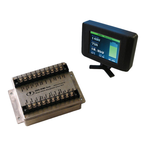
Developed to address the need to build safer, neater EV conversions,
the ZEVA Electric Vehicle Management System combines several
common functions required by EVs into one device:
• Battery Management System (BMS) Master Unit: Monitors your
BMS cell modules and takes action to protect your battery pack.
• Staged Precharging: Most motor controllers require a precharge
(soft-start) system to slowly charge up their internal capacitors
before they are enabled.
• Contactor control: Many EVs run multiple contactors for redundant safety.
This device manages auxillary contactors, which must be engaged when either driving
or charging.
• Charge/drive interlock: Ensures that the vehicle cannot be driven while plugged in.
• Status light and buzzer: A multicolour LED indicates the vehicle status, and a buzzer
gives audible warning of any errors detected.
Installation2.
The EVMS should be mounted securely to the vehicle using screws through
the four 5mm holes on the case anges.
There are 20 I/O terminals to connect for full functionality. A recommended
wiring diagram is overleaf. The use of forked crimp terminals is recommended
for the most reliable connections to the EVMSs. Wire gauge used for
most connections should be around 18-20 AWG, to ensure reasonable
mechanical strength. Small multicore cable is acceptable for the LED and
buzzer wiring harness.
Status LED and Buzzer3.
The status LED may display the following codes:
Blue, blinking: Vehicle idle (sleep)•
Blue: Charging enabled•
Green, ashing: Precharging•
Green: Drive enabled•
Red: BMS error•
Red, ashing: Precharge error•
Green/red ashing: BMS shut down drive•
Blue/red ashing: BMS shut down charger•
The buzzer will sound continuously on BMS error, or intermittently
on precharge error.
Zero Emission Vehicles Australia http://ww.zeva.com.au
Description of I/O Terminals:5.
+12V:• A permanent +12V supply (9-16V range),
in series with any emergency stop switches to ensure
everything downstream from the EVMS (charge and drive
systems) switch off immediately in an emergency.
Ground:• Connect this to chassis ground in your vehicle
(not traction circuit negative)
Key In:• Should see +12V when they key is turned on,
ground or oating otherwise.
Chg Sense:• This terminal should be pulled to ground
whenever you wish to charge. Typically achieved with
either a normally-open switch on your charge door, or an
AC relay that closes when the charge cable is plugged in.
BMS In:• This terminal should be pulled to ground
whenever there is no error reported from the BMS
modules. If using a one-wire BMS system, connect one end of your cell module daisy
chain to ground and the other end to this terminal.
Status RGB:• Outputs for Red, Green and Blue pins on the multicolour status LED
(should be installed in the vehicle cabin).
Buzzer:• Connect this to the positive terminal on the included piezo buzzer (should
be installed in the vehicle cabin).
Ground:• May be used as the ground connection for both the status LED and buzzer.
Prech A & B:• Connect these to either side of your main contactor. These The polarity
is important: A should be on the battery side, B should be on the controller side.
Drive Enable:• Connections to the drive enable relay, which will close when the
vehicle is allowed to drive. Best used to switch in either the controller enable or throttle
signal to controller.
Charge Enable:• Connections to the charge enable relay, which will close when the
vehicle may be charged. These internal relays rated to 10A current at either 250VAC or
28VDC. They are not suitable for switching typical traction pack DC voltages, or high
charge currents. Unless using a low current charger, in most cases you will need to use
the internal relay to switch an external power relay to control AC power to the charger.
Main Ctr:• This terminal goes to the positive connection on your main contactor.
Ground:• May be used for the negative connection on your main contactor.
Aux Ctr:• This terminal goes to the positive connection on your auxillary contactor(s).
Ground:• May be used for the negative connection on your auxillary contactor(s).
6. BriefSpecications
Power supply: 9-16VDC (~20mA idle, 5A max)•
Suitable for traction packs: 12-160VDC •
Dimensions: 150x100x50mm•
Casing: Fully enclosed die cast aluminium, weatherproof to IP65 •
Internally fused, reverse voltage and over-voltage protected •
The ZEVA EV Management System is proudly
designed and manufactured in Australia.
Zero Emission Vehicles Australia http://ww.zeva.com.au


