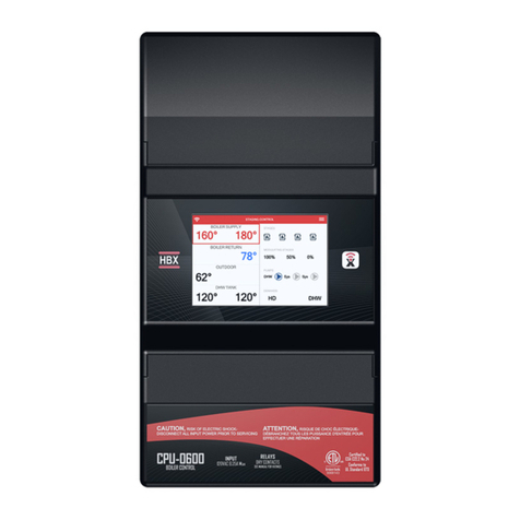
HBX ECO-1000 Operating instructions

Page 1
HBX Control Systems Inc.
ECO-1000
Central Processing Unit 1000
Version 1.35
©HBX Control Systems Inc. 2015
Phone: +1 (403) 720-0029 Fax: +1 (403) 720-0054
Email: info@hbxcontrols.com Web: www.hbxcontrols.com
HBX Control Systems Inc.
4516 - 112th Avenue SE
Calgary, AB Canada T2C 2K2
Geothermal Programming Guide

HBX ECO-1000 HVAC Control
Version 1.35
Page 2
Demand Signal 1 - This signal is only used in a
geothermal application as a heat demand signal.
Demand Signal 2 - This signal is only used in a
geothermal application as a cooling demand signal.
Demand Signal 3 - This signal is only used in a
geothermal application, for a fault indicator.
Thermistor 1 - Tank Sensor
Thermistor 2 - GND loop or cold tank sensor
for geothermal applications, solar sensor in solar
applications.
Thermistor 3 - Outdoor Sensor / return sensor for
solar.
P3 Relay - Used for a reversing valve in geothermal
applications or as solar pump 2 in a solar system.
P2 Relay - Used as a geo-circulating pump in a
geothermal application or as solar pump 1 in a solar
system.
P1 Relay - Used as a geothermal circulating pump or
tank 1 pump in a solar system.
Supply Power - the 3-wire 120VAC input to the
control. Protected by a 30Amp breaker or fuse.
Misc Relay 1 - This relay is the default relay for
bringing on the rst geothermal stage, or the solar
backup.
Misc: Relay 2 - This relay is the default relay for
bringing on the 2nd geothermal stage or for a hi temp
dump contact in a solar system.
Misc Relays 1&2 are Dry Contacts and rated for
a max of 10Amps
21
SD
1
SD
1
43
SD
2
SD
2
65
SD
3
SD
3RG
021
82
N
L
7262
RG
021
52
N
L
4232
RG
021
22
N
L
1202
RG
021
91
N
L
8171
LR
2
LR
6151
2
LR
1
LR
4131
1
MT
3
MT
2111
3
MT
2
MT
019
2
MT
1
MT
87
1
v042-02 v042-02 v042-02
EREHREWOPTCENNOCTONOD
A01 A01
A01 A01A01
0001OCE
XBH TINUGNISSECORPLARTNEC
yaleR3P
yaleR2P
yaleR1P
CAV021rewoPylppuS
2yaleR:csiM
1yaleR:csiM
1langiSdnameD
2langiSdnameD
3langiSdnameD
1rotsimrehT
2rotsimrehT
3rotsimrehT
Terminal Designations for ECO-1000

HBX ECO-1000 HVAC Control
Version 1.35
HBX ECO-1000 HVAC Control
Version 1.35
© HBX Control Systems Inc. 2015 Page 3
PROGRAMMING
DISPLAY FEATURES
The HBX display is a 128 x 64 pixel, back-lit graphic display on a blue background. In addition to displaying text
and icons it has the ability to provide you with visual graphing capabilities. These graphing capabilities will allow
you to get representative data and trending information of up to 2 independent feedback values.
Standard Geothermal Screen
System Status
S
Tank
GND Loop
Outdoor
Setpnt 1
109
48
54
72
Target
º
F
ºF
ºF
ºF
110
HD CD FLT SP1 SP2 SP3
WWSD
Heat Demand
ON
Set Back Mode
ON
Warm Weather Shut Down
ON
Target
Temperature
Shown in
Column below
Real Time and Date Shown
Temperature Feedback
( deg. Fahrenheit shown)
Cooling Demand ON
Setpoint ON Indicator
Fault Indicator
Mon Feb 14 2011 12:00:45

HBX ECO-1000 HVAC Control
Version 1.35
Page 4
HBX ECO-1000 HVAC Control
Version 1.35
NAVIGATING THE CONTROL
The four large red buttons labeled “A”, “B”, “C”, and “D” are used to make your way through the programming
options within the Control.
Pressing the “A” or “B” button while
viewing the initial “System Status” and
“System Function” main screens will
swap from screen to screen. Pressing
the “D” button will take you to the
“Programming Options” screen.
Pressing the “D” button again will
revert to the main system screens.
Once in the “Programming Options”
menu you may move the selection
indicator up and down by pressing the A and B buttons, pressing the “C” button will enter the selected option.
Pressing the “C” button on options with limited choices (ie. on/off, yes/no) will toggle the selection.
Pressing the “A” and “B” buttons on options with variable numerical choices (ie. temperature values, time settings)
will increase and decrease the selected amount. Pressing the “C” button upon completion will forward you to the next
step.
The “D” button can be used to revert to the previous menu.
AAB
BC
CD
D
Input: 120VAC 60Hz 5A
Relays: 240VAC 10A
Demand Signal: 20 - 240V
Model: CPU - 1000
CAUTION,
RISK OF ELECTRICAL SHOCK - DISCONNECT POWER PRIOR TO SERVICING
Certified to CSA C22.2 No 24
Conforms to UL Standard 873
Central Processing Unit
ECO-1000
Program Lock Feature
To minimize the potential for unauthorized tampering of your control after commissioning, you have the ability to
limit/lock the programming menus.
To lock the control, use two ngers to press and hold down the A and B buttons simultaneously for approximately 10
secs.
To unlock the control, use two ngers to press and hold down the C and D buttons simultaneously for approximately
10 secs.
If the display ashes erratically, remove your ngers from the buttons and try again by pressing both buttons
at the same time.
Lock Feature Unlock Feature
AAB
BC
CD
D
Input: 120VAC 60Hz 5A
Relays: 240VAC 10A
Demand Signal: 20 - 240V
Model: CPU - 1000
CAUTION,
RISK OF ELECTRICAL SHOCK - DISCONNECT POWER PRIOR TO SERVICING
Certified to CSA C22.2 No 24
Conforms to UL Standard 873
AAB
BC
CD
D
Input: 120VAC 60Hz 5A
Relays: 240VAC 10A
Demand Signal: 20 - 240V
Model: CPU - 1000
CAUTION,
RISK OF ELECTRICAL SHOCK - DISCONNECT POWER PRIOR TO SERVICING
Certified to CSA C22.2 No 24
Conforms to UL Standard 873

Page 5
HBX ECO-1000 HVAC Control
Version 1.35
HBX ECO-1000 HVAC Control
Version 1.35
2A Geothermal Select
Selecting the geothermal option will setup the ECO-1000 to display all options applicable to
a geothermal application.
3A Geothermal Status
This screen will be visible for approximately 5 seconds to identify the application you have
selected.
1.26
4A Geo System Status
Temperatures visible depend on the settings currently active.
The values shown here are with no sensors connected, or terminals removed
TARGET
Tank open °F 110
GNDLoop open °F
Outdoor open °F
Setpnt1 open °F
System Status
WED FEB 11 2009 11:07:02
1 Choose Control Type
The ECO-1000 can be congured as either a Geothermal or Solar specic hydronic control.
This screen will only stay on the rst time you power up the control. This screen will display
for ve seconds each time the control is started after you have selected the control type.
Choose Control Type
1) Geothermal
2) Solar
5A Geo System Function
System function displays currently active pumps, heat pumps and cycles.
You can toggle between main screens by pressing either the “A” or “B” button.
CYCLES
System Pump OFF °F 0
Heat Pump OFF °F 0
Backup OFF °F 0
System Function
7A Programming Options
1) Control Options
2) Geothermal Option
3) Change Designs
4) Setpoint Options
5) Setback Options
6) Graphing
7A7A
1) Control Options
2) GeoThermal Options
3) Change Designs
4) Setpoint Options
5) Setback Options
6) Graphing
Programming
6 System Status Extra
The third system screen displays extra sensors if applicable in your system.
66
Target
Extra OFF °F
Extra OFF °F
System Status
1
2A
3A
4A
5A
6
7A

Page 6
12 Change Time: Year
Select the appropriate year by pressing the “A” button to decrease and the “B” button to
increase the year. Press the “C” button to proceed.
1212
Year 2000
13 Change Time: Month
Select the appropriate month (1-12) by pressing the “A” button to decrease and the “B”
button to increase the month. Press the “C” button to proceed.
1313
Month 00
14 Change Time: Day
Select the appropriate day of the month (1-31) by pressing the “A” button to decrease and
the “B” button to increase the day. Press the “C” button to proceed.
1414
Day 00
9A Display Options: Menu
Display options allow you to: set your date and time; reset the internal relay counter for
pump and heat pump cycles; program and display either ºF or ºC; program the Control
to allow for Daylight Savings; access website information for HBX; and clear the stage
accumulated hours counter.
9A9A
1) Display Options
2) Always HD? N
3) Always CD? N
4) Mins and Maxs
5) Testing
6) Stage Run Times
7) Use Zone Module? N
Control Options
10 Display Options: Menu
Display options allow you to: set your date and time; reset the internal relay counter for
pump and heat pump cycles; program and display either ºF or ºC; program the Control
to allow for Daylight Savings; access website information for HBX; and clear the stage
accumulated hours counter.
1010
1) Change Time
2) Reset Cycles
3) Display in °F
4) D-lite savings? N
5) Contact HBX
6) Reset Run Times
Display Options
11 Display Options: Change Time
It is recommended that you setup the correct time on your Control before conguring other
options, as the real-time settings are effected by the “Change Time” feature.
1111
1) Change Time
2) Reset Cycles
3) Display in °F
4) D-lite savings? N
5) Contact HBX
6) Reset Run Times
Display Options
8A Control Options
The control options area contains options for changing the display, setting constant heat/
cooling demands; testing/viewing activity and enabling zone control. To enter the desired
selection, press the “C” button. For example, with line 1 ashing, press button “C” to enter
the “Control Options screen”.
8A8A
1) Control Options
2) GeoThermal Options
3) Change Designs
4) Setpoint Options
5) Setback Options
6) Graphing
Programming
8A
9A
10
11
12
13
14

Page 7
18 Display Options: Reset Cycles
Pressing the “C” button with the “Reset Cycles” option selected will reset the internal relay
counter for heat pumps and heat pump cycles. Heat pump and pump cycles are visible on
the “System Function” screen.
1) Change Time
2) Reset Cycles
3) Display in °F
4) D-lite savings? N
5) Contact HBX
6) Reset Run Times
Display Options
18
18
19 Display Options: Display in °F/°C
Pressing the “C” button with the “Display in °F/°C” option selected will allow you to
program the Control and display in either ºF or ºC scales.
1919
1) Change Time
2) Reset Cycles
3) Display in °C
4) D-lite savings? N
5) Contact HBX
6) Reset Run Times
Display Options
20 Display Options: D-Lite Savings
Pressing the “C” button with the “D-Lite Savings” option selected will allow you to program
the Control to allow for Daylight Savings time shifting.
2020
1) Change Time
2) Reset Cycles
3) Display in °F
4) D-lite savings? Y
5) Contact HBX
6) Reset Run Times
Display Options
21 Display Options: Contact HBX
Pressing the “C” button with the “Contact HBX” option selected will display the
manufacturer contact information and the units individual serial number.
2121
1) Change Time
2) Reset Cycles
3) Display in °F
4) D-lite savings? N
5) Contact HBX
6) Reset Run Times
Display Options
15 Change Time: Weekday
Select the appropriate day of the week (1-7) by pressing the “A” button to decrease and the
“B” button to increase the day. Press the “C” button to proceed.
Sunday = 1
1515
Weekday 1
(Sunday = 1)
16 Change Time: Hour
Select the appropriate hour of the day (0-24) by pressing the “A” button to decrease and the
“B” button to increase the hour. Press the “C” button to proceed.
Midnight = 0:00
1616
Hour 00
17 Change Time: Minute
Select the appropriate minute of the hour (0-60) by pressing the “A” button to decrease and
the “B” button to increase the minute. Press the “C” button to proceed.
1717
Min 00
15
16
17
18
19
20
21

Page 8
22 Display Options: Contact HBX Continued
Contact HBX Controls directly and display your Controls ID number
2222 HBX Control Systems
Calgary, AB, Canada
1-403-720-0029
www.hbxcontrols.com
ID Serial: xxxxxxxxxx
Press B to Continue
23 Display Options: Reset Run Times
Pressing the “C” button with the “Reset Run Times” option selected will clear the stage
accumulated hours counter. To view the stage runtime, select the “Stage Run Times” option
within the “Control Options” menu.
2323
1) Change Time
2) Reset Cycles
3) Display in °F
4) D-lite savings? N
5) Contact HBX
6) Reset Run Times
Display Options
24A Control Options: Always Heat Demand
Always HD allows you to set a permanent heat demand and does not require the use of an
external signal. Eg. in a commercial heat pump application.
W.W.S.D. will override the heat demand and shut off the heat pumps if not in
cooling mode.
24A24A
1) Display Options
2) Always HD? Y
3) Always CD? N
4) Mins and Maxs
5) Testing
6) Stage Run Times
7) Use Zone Module? N
Control Options
25A Control Opt.: Always Cooling Demand
Always CD allows you to set a permanent cooling demand and does not require the use of
an external signal. Eg. in a commercial heat pump application.
C.W.S.D. will override the heat demand and shut off the heat pumps if not in
heating mode.
25A25A
1) Display Options
2) Always HD? N
3) Always CD? Y
4) Mins and Maxs
5) Testing
6) Stage Run Times
7) Use Zone Module? N
Control Options
27 Mins and Maxs: Thermistors
Allows you to look at a maximum of six different thermistor min/max temperature
extremes and reset back to zero. To see updated Min/Max values return to the System Status
screen to refresh the view.
2727
1) Thermistor 1
2) Thermistor 2
3) Thermistor 3
4) Thermistor 4
5) Thermistor 5
6) Thermistor 6
7) Reset All
Mins and Maxs
28 Thermistor: Captured Data
Each thermistor has its highest and lowest temperatures stored, as well as the time that this
temperature was reached and the period of time that it spent at this value.
2828
01/01/09 Min Temp
00HRS 223˚F
01/01/09 Max Temp
00HRS 223˚F
Thermistor 1
26A Control Options: Mins and Maxs
This allows you to view extreme temperatures that the thermistor has been subjected to.
These values can be reset at any time.
26A26A
1) Display Options
2) Always HD? N
3) Always CD? N
4) Mins and Maxs
5) Testing
6) Stage Run Times
7) Use Zone Module? N
Control Options
22
23
24A
25A
26A
27
28

Page 9
30A Control Options: Testing
This allows you to manually test/run each relay for up to 30 seconds.
You can cycle the relay faster by pressing the “C” button, this skips the 30
second elapse time.
30A30A
1) Display Options
2) Always HD? N
3) Always CD? N
4) Mins and Maxs
5) Testing
6) Stage Run Times
7) Use Zone Module? N
Control Options
29 Mins and Maxs: Reset All
When formatting the Control existing min/max values are reset. Selecting the “Reset All”
option clears the time and date stamps.
2929
1) Thermistor 1
2) Thermistor 2
3) Thermistor 3
4) Thermistor 4
5) Thermistor 5
6) Thermistor 6
7) Reset All
Mins and Maxs
31 Testing: Relays
There are ve relays on the main control box. Relays six and higher will be run with the
corresponding Expansion Module connected. By continually pressing the “A” button you can
access extra screens showing Relays #8 and higher.
3131
1) Relay #1
2) Relay #2
3) Relay #3
4) Relay #4
5) Relay #5
6) Relay #6
7) Relay #7
Testing
32 Testing: PWM
The third screen is displayed by pressing the “A” button on the last selection of the previous
screen. PWM relays are accessible here.
3232 16) Relay #16
17) Relay #17
18) PWM #1
19) PWM #2
20) PWM #3
21) PWM #4
22) PWM #5
33 Testing: Relays Off
This screen informs you that the Control is reverting the relays to an off state.
3333
Waiting for relays
to turn off
35A Control Options: Stage Run Times
This allows you to view cumulative run times for your heat pump stages. This is reset in the
“Display Options” menu.
35A35A
1) Display Options
2) Always HD? Y
3) Always CD? N
4) Mins and Maxs
5) Testing
6) Stage Run Times
7) Use Zone Module? N
Control Options
34 Testing: Relay On
Pressing the “C” button on selected relays will activate the test sequence.
3434
Relay 1 is on
29
30A
31
32
33
34
35A

Page 10
36 Stage Run Times
This screen will display staging runtimes in a geothermal system, and the backup system
runtime in a solar installation.
Press the “D” button to exit
3636
1) 0:00
Stage Run Times
37A Control Options: Use Zone Module
This option enables the use of the HBX ZON-0500 zone control to control heating/
cooling distribution to independent zones in a system.
37A37A
1) Display Options
2) Always HD? Y
3) Always CD? N
4) Mins and Maxs
5) Testing
6) Stage Run Times
7) Use Zone Module? Y
Control Options
38A Geothermal Options
The geothermal options menu provides settings specic to your geothermal installation.
38A38A
1) Control Options
2) GeoThermal Options
3) Change Designs
4) Setpoint Options
5) Setback Options
6) Graphing
Programming
39A Geo Options: Heat Pump
The heat pump menu allows you to customize the settings for your systems heat pumps.
39A39A
1) Heat Pmp Options
2) Geo Settings
3) Fault Settings
4) Backup Settings
5) Heating Priority? N
GeoThermal options
40A Geo Options: Staging
These steps provide the necessary options to congure the heat pump staging components
of your system.
40A40A
1) Staging Options
2) Pump Options
3) # of Stages 1
4) Rotate Heat Pmps? Y
5) Rotate Cycles
GeoThermal Options
41A Staging: 2 Stage HP
Enable the 2 stage heat pump option if you are utilizing dual stage heat pumps or heat
pumps with 2 compressors per unit.
41A41A
1) 2 Stage HPump? Y
2) Fixed First? N
3) Fixed Last? N
4) Lo/Lo -Hi/Hi? N
5) Min ON LagTime
6) Max OFF LagTime
Staging Options
42A Staging: Fixed First
Fixed rst designates a heat pump to function as the initial ring device, regardless of
settings such as rotate heat pump. This will consistently be the rst to re when a heat
demand is present.
42A42A
1) 2 Stage HPump? N
2) Fixed First? Y
3) Fixed Last? N
4) Lo/Lo -Hi/Hi? N
5) Min ON LagTime
6) Max OFF LagTime
Staging Options
36
37A
38A
39A
40A
41A
42A

Page 11
43A Staging: Fixed Last
Fixed last designates a heat pump to function as the last ring device, regardless of setting
such as rotate heat pump. This will consistently be the last to re when a heat demand is
present.
43A43A
1) 2 Stage HPump? N
2) Fixed First? N
3) Fixed Last? Y
4) Lo/Lo -Hi/Hi? N
5) Min ON LagTime
6) Max OFF LagTime
Staging Options
44A Staging: LoLo/HiHi
The “Lo/Lo - Hi/Hi” function instructs a system containing a pair of 2 stage heat pumps
to engage the rst stage of each prior to igniting the second stage of either heat pump. The
“2 Stage HPump” option must be set to “Y” and two or more stages must be present.
44A44A
1) 2 Stage HPump? N
2) Fixed First? N
3) Fixed Last? N
4) Lo/Lo -Hi/Hi? Y
5) Min ON LagTime
6) Max OFF LagTime
Staging Options
45A Staging: Min HP Lagtime
Use this setting to set the minimum time between heat pump stages staging on.
45A45A
1) 2 Stage HPump? N
2) Fixed First? N
3) Fixed Last? N
4) Lo/Lo -Hi/Hi? Y
5) Min ON LagTime
6) Max OFF LagTime
Staging Options
46A Min HP Lagtime
Set this value to be the minimum amount of time between heat pump stages turning on. 1
minute is the minimum.
46A46A Min ON LagTime
1 mins
47A Staging: Max Off Lagtime
Set this value to be the maximum time between heat pump stages turning off.
47A47A
1) 2 Stage HPump? N
2) Fixed First? N
3) Fixed Last? N
4) Lo/Lo -Hi/Hi? Y
5) Min ON LagTime
6) Max OFF LagTime
Staging Options
48A Max Off Lagtime
Set this time to be the maximum time desired between heat pump stages turning off. This
can be set as low as 1 second.
48A48A Max OFF LagTime
60 Secs
49A Geo Options: Pumps
Access pump options to setup and differentiate between heat pump circulators and system
pumps with post purge features.
49A49A
1) Staging Options
2) Pump Options
3) # of Stages 1
4) Rotate Heat Pmps? Y
5) Rotate Cycles
GeoThermal Options
43A
44A
45A
46A
47A
48A
49A

Page 12
56A
1) 1 Pump/HeatP? N
2) Pumps Always ON? N
3) Post Purge 1 Sec
4) Use Tank Pumps? Y
5) AIR/Zone Pumps? N
Pump Options
50A Pumps: 1 Pump/HP
N = Heat pump circulators controlled by heat pump circuit
Y = Heat pump circulators controlled by ECO-1000
When selected ‘Y’ the post purge time is activated for the pumps in the system.
50A
1) 1 Pump/HeatP? N
2) Pumps Always ON? N
3) Post Purge 1 Sec
4) Use Tank Pumps? N
5) AIR/Zone Pumps? N
Pump Options
51A Pumps: Pump Always On
Gives you the option to run all of the pumps continuously, regardless of a call for heat.
All connected pumps will be permanently on.
51A
1) 1 Pump/HeatP? N
2) Pumps Always ON? N
3) Post Purge 1 Sec
4) Use Tank Pumps? N
5) AIR/Zone Pumps? N
Pump Options
53A Pumps: Post Purge
Program a post purge cycle which runs all pumps for a selectable duration (1-240 Secs) after
the initial off-signal has been sent.
53A53A
1) 1 Pump/HeatP? N
2) Pumps Always ON? N
3) Post Purge 1 Sec
4) Use Tank Pumps? N
5) AIR/Zone Pumps? N
Pump Options
54A Post Purge Time
Set the time for pumps to run after a heat demand has been satised. This features process
is to circulate tempered water into the loop which would otherwise be trapped in the heat
pump, causing energy waste.
54A54A Post Purge Time
1 Secs
52A Pumps Always On: Caution
All connected pumps will be permanently on.
52A52A
This Setting will
Turn all pumps on
in the System
Press B to Continue
CAUTION
55A Use Tank Pumps
This setting is used when you wish to utilize individual system pumps for two separate
temperatures. Each system pump will run only when there is a demand for its respective
temperature, and 1 or more heat pumps are running.
These pumps are usually between the heat pump and the tank.
55A
1) 1 Pump/HeatP? N
2) Pumps Always ON? N
3) Post Purge 1 Sec
4) Use Tank Pumps? Y
5) AIR/Zone Pumps? N
Pump Options
57A Geo Options: # of Stages
Set the number of heating/cooling stages in the system.
56A56A
1) Staging Options
2) Pump Options
3) # of Stages 1
4) Rotate Heat Pmps? Y
5) Rotate Cycles
GeoThermal Options
56A AIR/Zone Pumps
This setting is used when you wish to utilize Fan-Coils and Floor Radiant pumps. P1 (Fan-
Coil Pump), will come on when an HD or CD is given directly on the control and P2 (Zone
Pump), will come on only when an HD comes from zone control. Also with these pumps,
the temperature in the tank must be within 10 differential of the target before it can come
on for the protection of the zone.
50A
51A
52A
53A
54A
55A
57A
56A

Page 13
58A # of Stages
The number of stages available ranges from 1-14. For systems with 3 or more stages, EXP-
0100 modules are required.
Do not include a backup source as a stage, see Backup Settings.
57A57A Number of Stages
NB. HI/LO = 2 Stages
1
60A Geo Options: Rotate HP
Gives you the ability to rotate the heat pump sequence for lead/lag and effectively
accomplish equal run time per heat pump. Rotation is executed every 48 hours (running
hours).
59A59A
1) Staging Options
2) Pump Options
3) # of Stages 1
4) Rotate Heat Pmps? N
5) Rotate Cycles
GeoThermal Options
61A Geo Options: Rotate Cycles
This feature allows you to rotate the heat pumps according to the number of cycles you
have set.
59A59A
1) Staging Options
2) Pump Options
3) # of Stages 1
4) Rotate Heat Pmps? N
5) Rotate Cycles
GeoThermal Options
62A Rotate Cycles
Set the number of cycles at which you would like to rotate the heat pumps.
Rotation Cycles
2
59A # of Stages Caution
This screen will display to remind you that if you have 3 or more stages that you require the
adequate number of EXP-0100 modules attached.
58A58A
63A Geo Options: Settings
This setting allows for the setup of the geothermal setpoints and system setup.
60A60A
1) Heat Pmp Options
2) Geo Settings
3) Fault Settings
4) Backup Settings
5) Heating Priority? N
GeoThermal options
64A Dual Tank System
Set this option to “Y” if you are using a two tank system, one heating and one cooling. Can
also be used in a dual heat system. If “N” is selected, the tank will function as a hot storage
tank when the outdoor temperature is below the WWSD value and it will act as a cold
storage tank when the outdoor temp is above the WWSD value.
61A61A
1) Dual Tank System? Y
2) Hot Tank Setpoint
3) Cold Tank Setpoint
4) Cold Differential
5) Hot Differential
6) Min Loop Temp
7) Use Rev/3way Vlv? N
GeoThermal Settings
61A
62A
63A
64A
58A
59A
60A

Page 14
67A Settings: Cold Tank Setpoint
Choose this selection to setup a cold tank if the system is responsible for cooling demands.
This is the cooling setpoint regardless if cooling is done in a separate tank or not.
64A64A
1) Dual Tank System? N
2) Hot Tank Setpoint
3) Cold Tank Setpoint
4) Cold Differential
5) Hot Differential
6) Min Loop Temp
7) Use Rev/3way Vlv? N
GeoThermal Settings
69A Settings: Hot Tank 2 Setpoint
This option also functions as the Hot Tank 2 Setpoint. Choose this option when setting the
temperature for the second tank.
66A66A
1) Dual Tank System? N
2) Hot Tank Setpoint
3) Hot Tank 2 Setpoint
4) Hot 2 Differential
5) Hot Differential
6) Min Loop Temp
7) Use Rev/3way Vlv? N
GeoThermal Settings
68A Cold Tank Setpoint
If this setting is above 84ºF, screens 9A, 67A, 68A, and 69A will change to reect a 2 hot
tank system. This option will set your cold tank setpoint if below 84ºF and your second hot
tank setpoint if set above 84ºF.
65A65A Cold Tank Setpoint
50°F
9A9A
1) Display Options
2) Always HD? N
3) Always HD2? N
4) Mins and Maxs
5) Testing
6) Stage Run Times
7) Use Zone Module? N
Control Options 65A65A Hot Tank 2 Setpoint
142°F
66A66A
1) Dual Tank System? N
2) Hot Tank Setpoint
3) Hot Tank 2 Setpoint
4) Hot 2 Differential
5) Hot Differential
6) Min Loop Temp
7) Use Rev/3way Vlv? N
GeoThermal Settings 67A67A Hot 2 Differential
4°F
Must be over 84ºF to function as a hot tank setpoint.
69A Settings: Cold Differential
Choose this option to set the cooling differential.
When in 2 Hot tank mode, this option will set the second hot tank differential.
66A66A
1) Dual Tank System? N
2) Hot Tank Setpoint
3) Cold Tank Setpoint
4) Cold Differential
5) Hot Differential
6) Min Loop Temp
7) Use Rev/3way Vlv? N
GeoThermal Settings
65A Settings: Hot Tank Setpoint
This setting is used to set the desired temperature in the hot tank when there is a heat
demand present.
62A62A
1) Dual Tank System? N
2) Hot Tank Setpoint
3) Cold Tank Setpoint
4) Cold Differential
5) Hot Differential
6) Min Loop Temp
7) Use Rev/3way Vlv? N
GeoThermal Settings
66A Hot Tank Setpoint
This is the setpoint for the hot tank. Set to the desired temperature for the hot tank. To use
outdoor reset on the hot tank, scroll the value down (press the “A” button) until the screen
value reads “Outdoor Reset”. Following this the design temperatures must be set in the
“Change Designs” section of the control.
63A63A Hot Tank Setpoint
110°F
65A
66A
67A
68A
69A
9A 68A 69A 70A
69A

Page 15
70A Cold Differential
Set this temperature to be the desired cold tank differential. A differential of 4°F will allow
for 2 degrees above and/or 2 degrees below the desired temperature before a demand is
present.
67A67A Cold Differential
4°F
71A Settings: Hot Differential
Choose this section to set the heating differential.
68A68A
1) Dual Tank System? N
2) Hot Tank Setpoint
3) Cold Tank Setpoint
4) Cold Differential
5) Hot Differential
6) Min Loop Temp
7) Use Rev/3way Vlv? N
GeoThermal Settings
74A Min Loop Temperature
Set this to the minimum GND loop temperature you desire in your system. This will depend
on the percentage of glycol in your system, as well as environmental and system factors.
71A71A Min Loop Temperature
33°F
75A Settings: Use Rev/3 Way Valve
Set this option if you are controlling the reversing valve or 3-way valves to go from heating
to cooling.
72A72A
1) Dual Tank System? N
2) Hot Tank Setpoint
3) Cold Tank Setpoint
4) Cold Differential
5) Hot Differential
6) Min Loop Temp
7) Use Rev/3way Vlv? Y
GeoThermal Settings
72A Hot Differential
Set this temperature to be the desired hot tank differential. A differential of 4°F will allow for
2 degrees above and/or 2 degrees below the desired temperature before a demand is present.
69A69A Hot Differential
4°F
73A Settings: Min Loop Temperature
If a GND loop sensor is used on a single tank unit, then use this setting to set the minimum
loop temperature.
70A70A
1) Dual Tank System? N
2) Hot Tank Setpoint
3) Cold Tank Setpoint
4) Cold Differential
5) Hot Differential
6) Min Loop Temp
7) Use Rev/3way Vlv? N
GeoThermal Settings
76A Geo Options: Fault Settings
This option allows you to view and manage the heat pump faults.
73A73A
1) Heat Pmp Options
2) Geo Settings
3) Fault Settings
4) Backup Settings
5) Heating Priority? N
GeoThermal options
70A
71A
72A
73A
74A
75A
76A

Page 16
79A Fault Settings: Number of Faults
Line three displays the cumulative number of faults that have occurred.
76A76A
1) Use Fault? N
2) Reset Fault
3) Num of Faults = 0
4) Last Fault Time
00/00 2009 00:00
Fault Settings
80A Fault Settings: Last Fault
Line four indicates the time and date of the last fault.
77A77A
1) Use Fault? N
2) Reset Fault
3) Num of Faults = 0
4) Last Fault Time
00/00 2009 00:00
Fault Settings
81A Geo Options: Use Backup
HBX Control Systems Inc. has changed the backup on time. The Geothermal backup will
now activate at 2 times the “Minimum On Time”. The “Minimum On Time” is set within
the GEOTHERMAL OPTIONS/HEAT PUMP OPTIONS/ STAGING OPTIONS. This
feature allows the system to attempt to use the heat pumps for a longer duration before
bringing on the backup.
78A78A
1) Heat Pmp Options
2) Geo Settings
3) Fault Settings
4) Backup Settings
GeoThermal options
5) Heating Priority? N
82A Backup Settings: Use Backup
Set this option to “Y” if you are using a backup to accompany your heat pumps.
79A79A
1) Use Backup? Y
2) Use Backup Temp
3) Bckup Only Out Temp
4) Bckup Only Tnk Temp
Backup Settings
83A Use Backup Temp
Set this value to the outdoor temperature that you wish the backup to be enabled. Any
outdoor value below this temperature will allow the backup to turn on when called for.
80A80A
1) Use Backup? N
2) Use Backup Temp
3) Bckup Only Out Temp
4) Bckup Only Tnk Temp
Backup Settings
77A Fault Settings: Use Fault
Set this to “Y” if you would like to record and see fault conditions.
To use this section you must hook-up faults from the heat pump to pins 5 and 6
on the ECO-1000.
74A74A
1) Use Fault? Y
2) Reset Fault
3) Num of Faults = 0
4) Last Fault Time
00/00 2009 00:00
Fault Settings
78A Fault Settings: Reset Fault
Set this to clear the most recent fault condition.
75A75A
1) Use Fault? N
2) Reset Fault
3) Num of Faults = 0
4) Last Fault Time
00/00 2009 00:00
Fault Settings
77A
78A
79A
80A
81A
82A
83A

Page 17
84A Use Backup Temp
Set this temperature to the value you wish the backup to be enabled at (based on outdoor air
temperature), if you want the backup feature to be on constantly, ensure that this value is set
to “Off ”. This option will work in unison with the “Minimum On Time Feature”.
81A81A Use Backup Temp
40°F
85A Backup Only Out Temp
Geothermal heat pumps can become inefcient when outdoor temperatures become to
cold. This option allows you to set a temperature at which the backup will run at all times
in favour of the heat pump, the heat pump will not run until the outside temperature rises
above this setting.
82A82A
1) Use Backup? N
2) Use Backup Temp
3) Bckup Only Out Temp
4) Bckup Only Tnk Temp
Backup Settings
88A Backup Only Tank Temp
Set this to the maximum tank temperature for the heat pumps to run at. Once this
temperature has been exceeded, only the backup will heat the tank to the target temperature.
To function properly, this temperature should be set lower than the hot tank target
temperature.
85A85A Backup Only Tnk Temp
110°F
89A Heating Priority
Single Tank: If set to Y, and there is a heat demand and cooling demand simultaneously,
the control will disregard the call that is not priority until the priority demand is satised
Dual Tank: If set to Y, and there is a heat demand and cooling demand simultaneously, the
control will satisfy the priority tank before switching to the non priority tank
Two Hot Tanks: If set to Y, and there is a heat demand, the control will prioritize the rst
hot tank, not the second hot tank
86A86A
1) Heat Pmp Options
2) Geo Settings
3) Fault Settings
4) Backup Settings
5) Heating Priority? Y
GeoThermal options
86A Backup Only Out Temp
Set this value to be the temperature at which you wish the backup to constantly override the
heat pump, based on outdoor temperature.
83A83A Backup Only Out Temp
OFF
87A Backup Only Tank Temp
This feature is used when you would like a hotter temperature in your hot tank. This will
turn the heat pumps off if the temperature in the hot tank goes above this setting. This will
make sure that the heat pumps do not go into error.
84A84A
1) Use Backup? N
2) Use Backup Temp
3) Bckup Only Out Temp
4) Bckup Only Tnk Temp
Backup Settings
90A Change Designs
Change designs guides you through the steps to adjust system design parameters, optimizing
your systems performance.
87A87A
1) Control Options
2) GeoThermal Options
3) Change Designs
4) Setpoint Options
5) Setback Options
6) Graphing
Programming
84A
85A
86A
87A
88A
89A
90A

Page 18
93 Change Designs Design Room 1 Temp
This is the design temperature used in the heat curve calculation.
9090 Design Room Temp
70°F
94 Change Designs: Design Outside 1 Temp
In North America ASHRAE have a recommended outside temperature rating for each city
or region a heating control can work in. This takes into consideration some of the heat loss
from your building. You can change your outside design temperature here to reect your
specic circumstances.
Typical design temperatures are shown at the back of the General Installation Guide
9191 Design Outside Temp
6°F
95 Change Designs: Min System Temp
Minimum system temp is the lowest water temperature you would like in the hot tank. This
setting will supersede the outdoor reset calculation.
9292 Min System Temp
75°F
96 Change Designs: Warm Weather Shutdown
W.W.S.D. is the temp at which you decide to ignore a call for heat. This is an energy saving
feature. W.W.S.D. overrides the “Always Heat Demand” setting.
9393 W.W.S.D.
75°F
97 Change Designs: Cold Weather Shutdown
C.W.S.D. is the temp at which you decide to ignore a call for cooling. This is an energy saving
feature. C.W.S.D. overrides the “Always Cooling Demand” setting.
For single buffer tank systems utilizing permanent heat/ cool demands the
C.W.S.D. must be set higher than W.W.S.D.
9494 C.W.S.D.
OFF
91 Change Designs: Manual
Manual design allows you to customize each design temperature for your system. The design
temperature for outdoor reset will only work if hot tank setpoint is set to use outdoor reset.
8888
1) Manual
2) Format Control
Change Designs
92 Change Designs: Design System 1 Temp
Design system temp will allow you to provide the required heat for your radiant source, this
is set to be the maximum temperature required in the hot tank.
To use outdoor reset, “Hot Tank Setpoint” must be set to use outdoor reset.
8989 Design System Temp
110°F
91
92
93
94
95
96
97

Page 19
98 Change Designs: Format Control
When selected, all of the original settings are reloaded as in the “Factory Defaults” option.
In addition, the “Format Control” option will reset the designated functions for each
terminal.
9595
1) Manual
2) Format Control
Programming
99 Format Control: Caution
This screen is your nal opportunity to avoid formatting the options within the Control.
9696 CAUTION
All Settings will
be RESET to FACTORY
Settings
Press B to Continue
Press C to EXIT
101 Setpoint Options: Setpoints
You have the ability to work with up to 3 different setpoints. The default is set to “Off ”.
Select which setpoint you are going to operate, then press the “C” button to enter. Each
system setpoint is congured in the same manner.
9898
1) Setpoint 1 OFF
2) Setpoint 2 OFF
3) Setpoint 3 OFF
4) Merge Setpoints? N
Setpoint Options
100A Setpoint Options
Setpoints give you the option to utilize an independent heat/cool demand such as a fancoil,
DHW pre-heat tank, hot tub, pool or spa. HBX Expansion Modules are required to run
setpoints.
97A97A
1) Control Options
2) GeoThermal Options
3) Change Designs
4) Setpoint Options
5) Setback Options
6) Graphing
Programming
102 Setpoint Options: Setpoint Temperature
By selecting choice #1, you will pick the actual setpoint temperature to control around ± the
differential.
9999
1) Setpoint Temp
2) Heating
3) Cool Interlock? N
4) Differential
5) Lag Time
6) Demand Temp
Setpoint 1 Program
103 Setpoint Options: Setpoint Temperature
Enter value to correspond with setpoint temp thermistor/sensor location.
Setpoint works only with thermistor/sensor inputs.
100100 Setpoint 1 Temp
OFF
104 Setpoint Options: Setpoint Expansion Caution
Any changes to setpoint controls will prompt you to install one of the HBX Expansion
Modules Eg. EXP-0100 or EXP-0300.
101101 CAUTION
This Setting requires
An Extra module
Press B To Continue
98
99
100A
101
102
103
104

Page 20
107 Setpoint Options: Differential
Choice #4 “Differential” will allow you to set your margin for error in ºF or ºC around the
setpoint temperature.
104104
1) Setpoint Temp
2) Heating
3) Cool Interlock? N
4) Differential
5) Lag Time
6) Demand Temp
Setpoint 1 Program
108 Setpoint Differential
Setpoint differential value is the temp value which the Control will turn on and off around
the setpoint. In this example of 2ºF with a setpoint of 68ºF, the Control will turn on when
the temp falls below 67ºF and turn off when the temp rises above 69ºF.
105105 Setpoint 1 Diff’ntial
2°F
109 Setpoint Options: Lag Time
Choice #5 is “Lag Time”. This allows you to set a minimum off time between setpoint
demands. This helps to establish a cycle length between heat demands and reduce short
cycling.
106106
1) Setpoint Temp
2) Heating
3) Cool Interlock? N
4) Differential
5) Lag Time
6) Demand Temp
Setpoint 1 Program
110 Setpoint Lag Time
You have a range of 0 to 600 seconds for lag time, and is adjustable in 5 second increments.
107107 Setpoint 1 LagTime
0 S
111 Setpoint Options: Demand Temperature
Set this option to the desired tank temperature when the setpoint engages. This option can
be set to “No Demand”, or from 1-200ºF.
This setting will be set to “No demand” on a solar control.
108108
1) Setpoint Temp
2) Heating
3) Cool Interlock? N
4) Differential
5) Lag Time
6) Demand Temp
Setpoint 1 Program
105 Setpoint Options: Heating / Cooling
Choice #2 allows you to select either heating or cooling mode. Press “C” to toggle between
choices, eg. heating/cooling.
Heating - when the temperature drops below the setpoint, the relays engage.
Cooling - when the temperature rises above the setpoint, the relays engage
102102
1) Setpoint Temp
2) Cooling
3) Cool Interlock? N
4) Differential
5) Lag Time
6) Demand Temp
Setpoint 1 Program
106 Setpoint Options: Cool Interlock
If selected “Y”, this will allow cooling only and not a simultaneous heat demand. If selected
“N”, then heating and cooling can be delivered to the same zone space. Eg. tile oor
warming and air conditioning.
103103
1) Setpoint Temp
2) Heating
3) Cool Interlock? Y
4) Differential
5) Lag Time
6) Demand Temp
Setpoint 1 Program
105
106
107
108
109
110
111
Other manuals for ECO-1000
1
Table of contents
Other HBX Control System manuals
Popular Control System manuals by other brands

AIRTRONICS
AIRTRONICS M11X FHSS-3 operating manual

Parking Facilities
Parking Facilities PF5700 Installation, operation & maintenance manual

Johnson Controls
Johnson Controls HomeLink quick start guide

Imesa
Imesa ECC manual

Uponor
Uponor Smatrix Move PRO Installation and operation manual

Fagor
Fagor CNC 8055 TC Self-teaching manual