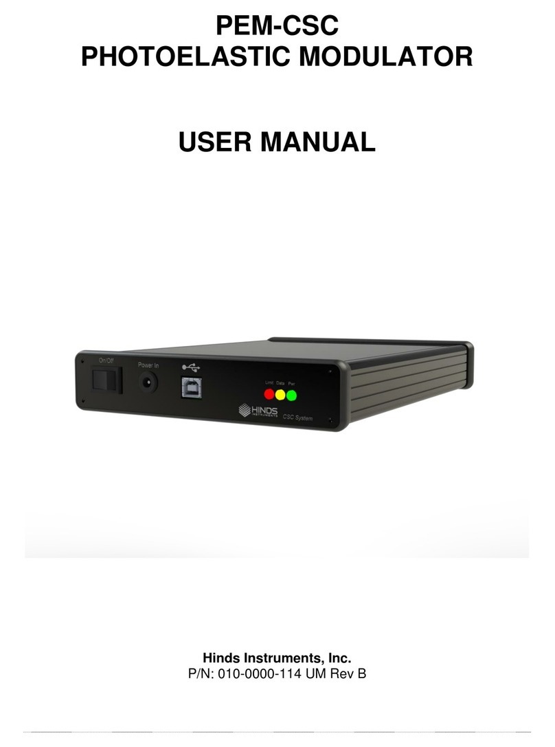
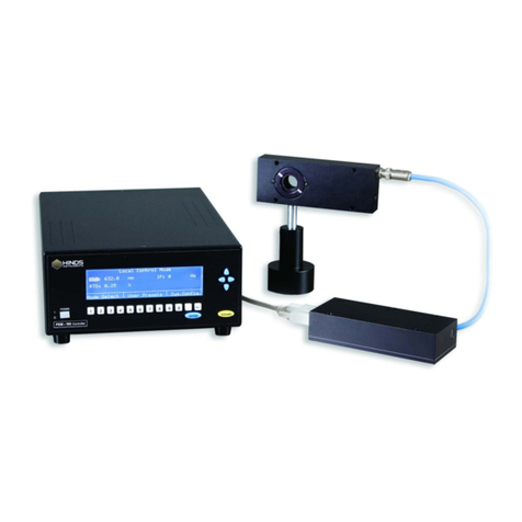
Hinds Instruments PEM200 User manual

PEM200
PHOTOELASTIC MODULATOR
USER MANUAL
Hinds Instruments, Inc.
P/N: 010-0000-095 UM Rev B

PEM200 User Manual ii
Copyright © 2020 by Hinds Instruments, Inc.
THIS DOCUMENT IS PROVIDED “AS IS” WITH NO WARRANTIES WHATSOEVER,
INCLUDING ANY WARRANTY OF MERCHANTABILITY, FITNESS FOR ANY PARTICULAR
PURPOSE, OR ANY WARRANTY OTHERWISE ARISING OUT OF ANY PROPOSAL,
SPECIFICATION OR SAMPLE. All rights reserved. No part of this publication may be
reproduced, stored in a retrieval system, or transmitted, in any form by any means, electronic,
mechanical, by photocopying, recording, or otherwise, without the prior written permission of
Hinds Instruments, Inc.
Information furnished by Hinds Instruments, Inc. is believed to be accurate and reliable;
however, no responsibility is assumed by Hinds Instruments, Inc. for its use; nor for any
infringements of patents or other rights of third parties which may result from its use. No license
is granted by implication or otherwise under any patent rights of Hinds Instruments, Inc.
In all respects, the English version of this manual is controlling.
The PEM200 and PEM-200 are covered by the following US patents: (1) 7,800,845, (2)
7,495,205, (3) 6,970,278, (4) 6,906,844, (5) 6,867,863, (6) 5,886,810, (7) 5,744,721,
(8) 5,652,673.
PEMLabsTM, Hinds Instruments and the Hinds Instruments, Inc. graphic logo are trademarks of
Hinds Instruments, Inc.
*Third-party brands and names are the property of their respective owners.

PEM200 User Manual 1
Table of Contents
Table of Contents..........................................................................................................1
Operators’ Safety Summary.........................................................................................1
Terms.....................................................................................................................1
WARNING ......................................................................................................................1
CAUTION .......................................................................................................................1
NOTICE..........................................................................................................................1
PEM-200 Controller Labels...................................................................................1
DC Power Supply..................................................................................................3
Covers ...................................................................................................................4
Operating Space ...................................................................................................4
Integration & Special Conditions.........................................................................4
Not Required.........................................................................................................5
Unpacking the PEM200.................................................................................................6
Shipping Damage Check......................................................................................6
Packaging Overview.............................................................................................7
Unpacking the PEM Optical Head........................................................................7
Special Instructions for I/FS50 Optical Head......................................................................8
Special Instructions for Series II Optical Heads..................................................................9
Series II FS Optical Heads..................................................................................................9
Series II ZS50 & ZS42 Optical Heads...............................................................................10
Series II ZS37 Optical Heads............................................................................................11
1 Introduction..............................................................................................................12
Overview..............................................................................................................12
2 PEM-200 Controller..................................................................................................13
PEM-200 Controller Front Panel ........................................................................13
PEM-200 Controller Rear Panel..........................................................................14
PEM-200 Controller Rear Panel Buttons..........................................................................14
PEM-200 Controller Rear Panel Connections ..................................................................14
PEM-200 Controller Rear Panel LEDs..............................................................................15
PEM-200 Controller Dimensions.......................................................................................15
3 Modulator Head Assembly ......................................................................................16
Optical Head........................................................................................................16
Controller....................................................................Error! Bookmark not defined.
4 Initial Set-Up.............................................................................................................19
Connecting the PEM Optical Head and Controller ...........................................19
Functional Check ..............................................................................................................20
5 PEM200 Software Setup .........................................................................................21
Installation...........................................................................................................21
Setup Running ..................................................................................................................22
Setup Complete ................................................................................................................23
6 PEM200 Control Software........................................................................................24
Setup of the PEM-200 Controller for Use with PEM Control ............................................24

PEM200 User Manual 2
Launching the PEM Control Software and Verifying Communication with the PEM-200 Controller
..........................................................................................................................................25
Main Interface ...................................................................................................................26
Scan Panel........................................................................................................................27
Debug Panel .....................................................................................................................29
Themes .............................................................................................................................30
Change COM port.............................................................................................................31
7 Communication Protocol.........................................................................................32
Port Settings......................................................................................................................32
Standard Commands for Programmable Instruments (SCPI) protocol ............................32
8 Troubleshooting.......................................................................................................43
9 Maintenance.............................................................................................................44
Calibration...........................................................................................................44
Adjustment of Peak Retardation Calibration.....................................................................44
Maintenance........................................................................................................44
Cleaning ..............................................................................................................45
Recommended Optics Cleaning Solutions .......................................................................45
Cleaning the Optics...........................................................................................................45
A Calibration................................................................................................................48
PEM-200 Calibration ...........................................................................................48
Calibration Theory ..............................................................................................48
Light Sources for Modulator Calibration...........................................................50
Calibration Using an Oscilloscope....................................................................51
Multiple Reflection Techniques .........................................................................53
Static Waveplate Techniques.............................................................................54
Bessel Function Zero Methods..........................................................................54
Bessel Function Ratio Methods.........................................................................56
Parallel Polarizer Calibration at a Single Wavelength......................................57
B Specifications..........................................................................................................61
General- Controller .............................................................................................61
Parameter Specifications ...................................................................................61
Input / Output Specifications .............................................................................61
Environmental.....................................................................................................62
Approvals............................................................................................................62
EMC & Safety Standards....................................................................................62
C Optical Head Specifications ...................................................................................63
D User Support Information.......................................................................................64
PEM 200 Limited Warranty.................................................................................64
Exclusions.........................................................................................................................64
Overview of the PEM 200 Help System .............................................................65
Return For Repair Procedure.............................................................................65
Packaging .........................................................................................................................66
Items To Include................................................................................................................66
Shipping Arrangements.....................................................................................................66
Return Shipping Address..................................................................................................66
Shipping Costs..................................................................................................................66

PEM200 User Manual 1
Operators’ Safety Summary
The general safety information in this summary is for operators of the PEM200
Photoelastic Modulator System. Specific warnings and cautions may be found
throughout the manual where they apply, but may not appear in this summary.
If the user sees the exclamation point symbol, they need to consult this section of the
user manual.
Terms
WARNING statements identify conditions or practices that could result in personal injury
or loss of life.
CAUTION statements identify conditions or practices that could result in damage to the
equipment or other property.
NOTICE statements identify conditions or practices that are important in proper use of
the equipment to get the expected results.
PEM-200 Controller Labels
CE: The CE certification label is located at the top right
corner on the PEM-200 Controller rear panel as shown in
figure S.1 below.
The power supply input is labeled with
“24V” as well as the DC connection label.
See DC Power Source below for details
and safety with the power supply.

PEM200 User Manual 2
USB: The USB label is located above the input of the
USB2.0 port for communication with any Windows 7 or
newer computer.
ON/OFF: The ON/OFF engraving is above the power switch. Ensure the power is off
before connecting or disconnecting SMA cables from HV outputs to optical head. More
details below.
WARNING: HARZARDOUS VOLTAGE:
USB
ON/OFF
CE Label
24V DC

PEM200 User Manual 3
High Voltage (HV) SMA connectors support hazardous electrical levels, up to 138Vrms.
Contact with High Voltage (HV) SMA outputs may cause severe shock or burn. Power
off the unit before connecting or disconnecting SMA cables to connectors and optical
head.
Avoid contact with SMA cable-ends or connectors other than to connect or disconnect
controller to optical head. Always connect or disconnect SMA cables with power off. Do
not turn on power until all cables are connected properly.
DC Power Supply
This product is intended to operate from a DC power source at 24 VDC. The main
power input is 90-264VAC, 47-63 Hz, 1.7A. A protective ground connection by way of
the grounding connector in the power cord is required for safe operation. Power line
requirements are listed in the specifications section.
The power cord provided with this instrument is less than 3 meters in length.
Use only the power cord and connector specified for your product to work with your
local power outlets. Use only a power cord that is in good condition.
The appliance inlet or plug on cord should always be positioned to be accessible by the
operator. To disconnect all power from the instrument, pull the power cord from the wall
outlet or from the appliance inlet. See Operating Space below for detail.
WARNING: Hazardous Voltage

PEM200 User Manual 4
Covers
To avoid personal injury, do not operate the PEM-200 Controller without the cover.
There are no user-serviceable parts inside the PEM-200 Controller. High voltages are
present within the controller.
With the cover properly installed, impact rating for the PEM200 is 5J.
Only remove the optical head cover as instructed in the unpacking instructions below.
Do not remove the cover of optical head for any other reason. Ensure the optical head
is disconnected from any SMA cables before removing cover. High voltages can be
present otherwise.
Do not remove the cover from the PEM-200 Controller or optical head unless you are
being actively supported by Hinds Instruments personnel.
Operating Space
Hinds Instruments suggests leaving 2-3 inches (5-8cm) minimum of space around the
PEM-200 controller to allow for safe connection and disconnection of all cables.
Keep liquids of all types away from PEM200, especially if flammable.
Integration & Special Conditions
The integration of the PEM into a measurement system by a customer doesn't involve
any change or modification to the PEM's operating electronics. Therefore, the PEM
doesn't create any additional safety issues in integration.
Out of range ambient conditions may cause slight degradation in the performance of a
PEM including slight frequency shift and reduced stability. Mounting the optical head by
any means other than the mount holes described in Section 3 may also lead to these
shifts.
Any use of the PEM200 outside of the manufacturer intended use, as specified in
this manual, could result in safety impairment.

PEM200 User Manual 5
Not Required
To operate the PEM200, there no requirements for:
•Safety Equipment Accessories
•Pollution Degree
•Ventilation
•Flow of air or cooling liquid
•Permanently connected equipment
•Sound level

PEM200 User Manual 6
Unpacking the PEM200
Shipping Damage Check
Inspect all system components for obvious shipping damage. The PEM200 is a
precision instrument that can be damaged by rough handling. The units are packaged
to minimize the possibility of damage in transit. Therefore, it is recommended that the
user save the specially designed shipping container for any future shipment of a
modulator unit.
In the event an order arrives in damaged condition, it is important that the following
steps be taken immediately. The title transfers automatically to the customer, once the
material is entrusted to the transport company.
1. DO NOT RETURN THE INSTRUMENT TO HINDS INSTRUMENTS, INC. until the
following steps are completed. Failure to follow this request will jeopardize user
claim with the insurance company.
2. If a “Shock Watch” is present on the outer shipping container or anywhere inside,
note the location and the condition of the shock watch. If the shipment receives
handling rough enough to trigger the shock watch, the watch will turn red.
3. Open the container and inspect the contents. Do not throw away the container or
any damaged parts. Try to keep all items in the same condition as originally
received.
4. Notify the Transport Company immediately in writing, preferably by facsimile or
email, about the shipping damage.
5. Wait for the transport company’s representative to inspect the shipment personally.
6. After inspection, request Hinds Instruments’ permission to return the damaged
instrument by calling the service department at (503) 690-2000 or email to
support@hindsinstruments.com. A return authorization number (RMA) will be
assigned to you.See Overview of the PEM200 Help System on page 65 for further
contact information.
7. Return approved items to Hinds Instruments Inc. at the following address:
Hinds Instruments, Inc.
7245 NE Evergreen Pkwy, Suite 150
Hillsboro, OR 97124-5850
8. After return permission is given and Hinds Instruments receives the instrument, an
estimate of the cost of repair will be sent to you in the event you choose to submit a
claim to the transport company.

PEM200 User Manual 7
Figure S.1 PEM200 Photoelastic Modulator in Shipping Case
Packaging Overview
The PEM200 packaging is separated into four sections:
•Power Supply Unit
•Optical Head
•SMA Cable Assembly, Power Cable
•PEM-200 Controller
Unpacking the PEM Optical Head

PEM200 User Manual 8
Figure S.2 I/FS50 Removing Shipping Disk
Figure S.3 Removal of White Cover on Optical Enclosure
Special Instructions for I/FS50 Optical Head
The following unpacking instructions are for an I/FS50 PEM optical head.
•Ensure the work surface is clean and free of dust
•Using a #1 Phillips screwdriver, remove the shipping disk
•The alternate side of the Optical Head is covered by tape to prevent dust and
other particles from entering the enclosure. This can be easily removed by
hand.
•Please save the shipping disk, screws and white cover in the event the PEM
needs to be transported.
Shipping Disk
Qty. 4 screws

PEM200 User Manual 9
Special Instructions for Series II Optical Heads
Included in all orders for Series II Optical Heads is a packet outlining instructions for
removing the Transducer Safety Clip.
•A Phillips screwdriver has been included in the packet for removal of the outer
lid of the optical enclosure
•Please follow the provided instructions carefully to avoid damaging the optical
assembly
Series II FS Optical Heads
1. Remove the 4 lid screws using the provided screwdriver.
2. Gently pull the yellow clip out. Grab the provided tabs on the lower half of the
clip. There is a split in the clip under the transducer. Separate the clip and lift it
out from around the transducer. Take care when removing a clip near transducer
wires. Save clips for future return or transportation of unit.
NOTE: DO NOT TURN OPTICAL HEAD OVER WHILE LID IS OFF –
OPTICS WILL FALL OUT
3. Replace lid. Extra screws are provided.
Figure S.4 Unpacking II/FSXX Optical
Head

PEM200 User Manual 10
Figure S.5 Unpacking II/ZS50 or II/ZS42 Optical Head
Series II ZS50 & ZS42 Optical Heads
1. Remove the 4 lid screws using the provided screwdriver.
2. Gently pull the yellow clip out. Grab the provided tabs on the lower half of the
clip. There is a split in the clip under the transducer. Separate the clip and lift
it out from around the transducer. Take care when removing a clip near
transducer wires. Save clips for future return or transportation of unit.
NOTE: DO NOT TURN OPTICAL HEAD OVER WHILE LID IS OFF –
OPTICS WILL FALL OUT
3. Replace lid. Extra screws are provided.

PEM200 User Manual 11
Figure S.6 Unpacking II/ZS37 Optical Head
Series II ZS37 Optical Heads
1. Remove the 4 lidsscrews using the provided screwdriver.
2. Gently pull the yellow clip out. Grab the provided tabs on the lower half of the
clip. There is a split in the clip under the transducer. Separate the clip and lift it
out from around the transducer. Take care when removing the clip near
transducer wires. Save clips for future return or transportation of unit.
NOTE: DO NOT TURN OPTICAL HEAD OVER WHILE LID IS OFF –
OPTICS WILL FALL OUT
3. Replace lid. Extra screws are provided.
Split

PEM200 User Manual 12
1
Introduction
Overview
The PEM200 Photoelastic Modulator is an instrument used for modulating or varying (at
a fixed frequency) the polarization of a light beam. Hinds Photoelastic Modulators are
used for measurement of circular and linear dichroism, birefringence, optical rotation,
ellipsometry, polarimetry, reflection difference spectroscopy and FTIR double
modulation.
The PEM200 principle of operation is based on the photoelastic effect, in which a
mechanically stressed sample exhibits birefringence proportional to the resulting strain.
Photoelastic modulators are resonant devices, each producing oscillating birefringence
at a fixed frequency in the low frequency ultrasound range (20 kHz to 82 kHz). These
factors result in a number of very useful advantages, which are unique to the PEM
including wide acceptance angle, large aperture and high modulation “purity.”
Figure 1.1 provides an overview of the PEM200 photoelastic modulator system which
includes the PEM-200 Controller, Optical Head, and the Head-to-Controller cables.
Figure 1.1 PEM200 Photoelastic Modulator

PEM200 User Manual 13
2
PEM-200 Controller
PEM-200 Controller Front Panel
The PEM-200 Controller front panel consists of six separate SMA connections:
HV:Two SMAs enclosed in the high voltage (“HV”) box are for interface between optical
head and controller. These connections are necessary to drive the PEM optical head.
These are the high voltage SMA connections. Please ensure that the PEM200 controller
is off or disconnected from power when making any connection with these SMA ports.
Order (+/-) does not matter when connecting SMAs from HV output to optical head
inputs. See Operators Safety Summary for more detail.
Ref Out: The “Ref Out” SMA will give a 3.3V TTL signal at the PEM’s selected
harmonic frequency for any triggering needs.
Trig Out: Trig Out is a second reference SMA reserved for future expansion or custom
customer triggering needs upon request.
Signal In & Aux In: Additional connections required for synchronous detection options.
Figure 2.1 PEM-200 Controller Front Panel

PEM200 User Manual 14
Figure 2.2 PEM-200 Controller Rear Panel
PEM-200 Controller Rear Panel
All electrical/electronic connections to the controller are made on the rear panel.
PEM-200 Controller Rear Panel Buttons
•Power Switch: The PEM-200 powers using the I/O switch. Push the selector to
the “I” position to power ON and “O” to power OFF
PEM-200 Controller Rear Panel Connections
•USB Type B Connection: The USB 2.0 Type B connector interface allows
communication to a PC. PEM200 software runs on Windows 7 or 10.
•24V Barrel Input: The barrel connection is the input for a 24VDC power brick.
USB Type B Input
ON/OFF Power Toggle
24V Power Input

PEM200 User Manual 15
Figure 2.3 PEM-200 Controller
PEM-200 Controller Rear Panel LEDs
•Power: Power will illuminate green whenever the PEM200 controller has power
and is on.
•Data: The yellow data LED will flash anytime there is communication between the
PC and PEM-200 controller. It will illuminate if the controller is attempting to detect
connection with the PEM optical head, or if the optical head connected is
inappropriate match for the controller hardware.
•Error: Error (red) will illuminate when the PEM controller reaches a limit of drive
voltage. PEM will go into idle state if connected and error occurs. To recover the
PEM from an error state, cycle the power on the PEM-200 controller and set the
PEM to a lower modulation amplitude.
PEM-200 Controller Dimensions

PEM200 User Manual 16
Figure 3.1 Model I/FS40, I/FS50, I/FS60, I/CF50 Optical Head
3
Modulator Head Assembly
The transducer-optical element assembly (called the “optical assembly”) is the heart of
a PEM200 photoelastic modulator. It consists of a rectangular or octagonal “window” of
optical material bonded to a quartz piezoelectric transducer. Both optical element and
transducer are tuned to the same frequency. This assembly oscillates and produces the
time-varying birefringence which is the basis of operation of the PEM.
This assembly, consisting of the optical head, controller and the cables which connects
them, is a single circuit. It is not intended to operate unless all three elements are
together.
CAUTION
Operation of the controller without the optical head attached may
result in damage to the controller.
Optical Head
The Optical assembly is housed in an enclosure called the “optical head.” Figures 3.1
through 3.5 provide dimensions for various optical head types.
Table of contents
Other Hinds Instruments Modulator manuals
