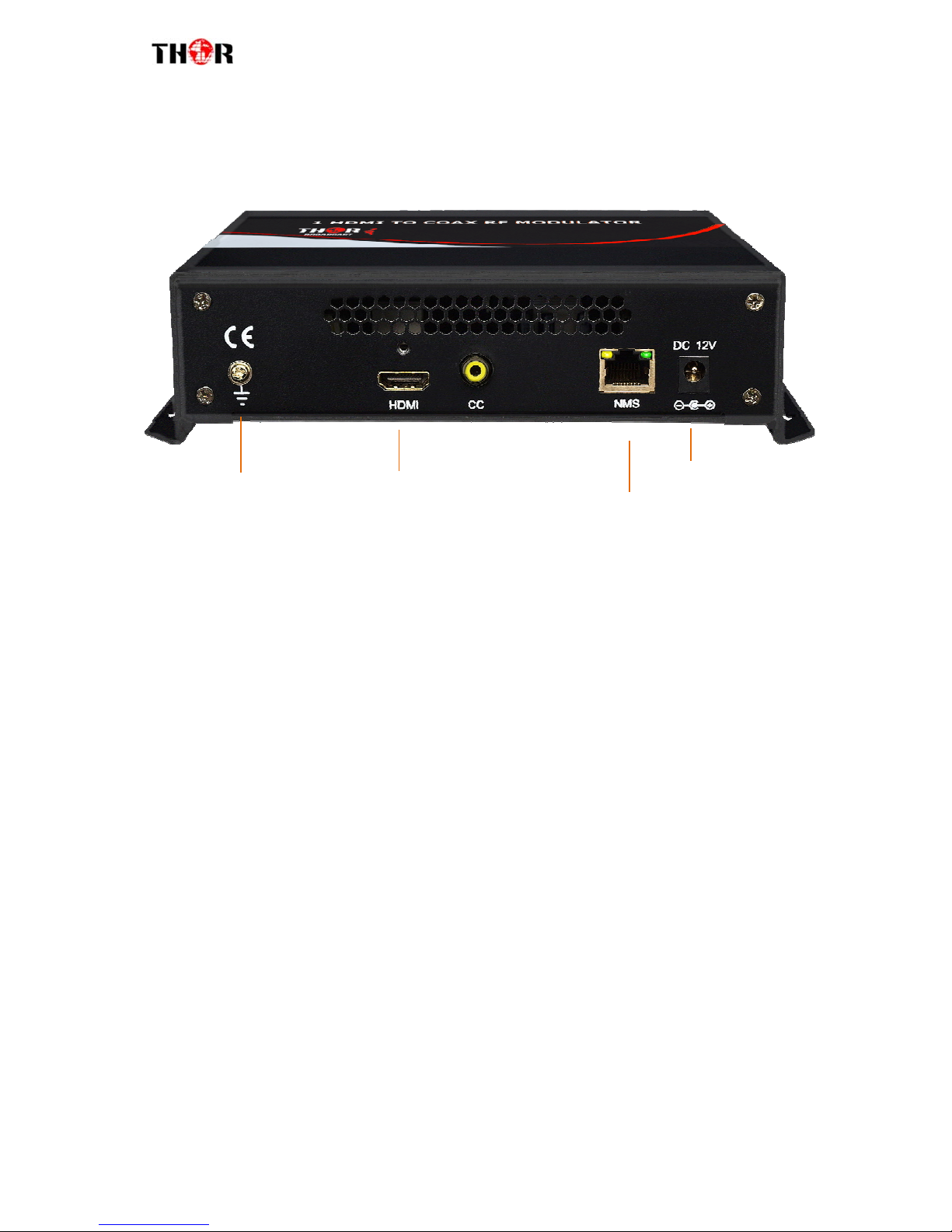
Thor Broadcast H-HDMI-CC-RF User manual

H-HDMI-CC-RF
User Manual
LosAngelesCASales@thorfiber.com1‐800‐521‐8467

H‐HDMI‐CC‐RF
ANotefromThoraboutThisManual
IntendedAudience
This user manual has been written to help people who have to use, integrate and to install the
product. Some chapters require some prerequisite knowledge in electronics and especially in
broadcasttechnologiesandstandards.
Disclaimer
NopartofthisdocumentmaybereproducedinanyformwithoutthewrittenpermissionofThor
Broadcast.Thecontentsofthisdocumentaresubjecttorevisionwithoutnoticeduetocontinued
progressinmethodology,designandmanufacturing.Thorshallhavenoliabilityforanyerroror
damageofanykindresultingfromtheuseofthisdocument.
CopyWarning
Thisdocumentincludessomeconfidentialinformation.Itsusageislimitedtotheownersofthe
productthatitisrelevantto.Itcannotbecopied,modified,or translated in another language
withoutpriorwrittenauthorizationfromThorBroadcast.

H‐HDMI‐CC‐RF
Directory
Contents
CHAPTER1INTRODUCTION................................................................................................................1
1.1PRODUCTOVERVIEW................................................................................................................................1
1.2KEYFEATURES.........................................................................................................................................1
1.3SPECIFICATIONS........................................................................................................................................2
1.4APPLICATIONDESIGNDRAWING..................................................................................................................4
1.5APPEARANCEANDDESCRIPTION..................................................................................................................5
CHAPTER2INSTALLATIONGUIDE........................................................................................................6
2.1SAFETYINSTRUCTIONS...............................................................................................................................6
CHAPTER3WEB‐PAGEMANAGEMENT...............................................................................................7
3.1LOGIN....................................................................................................................................................7
3.2OPERATION.............................................................................................................................................8
CHAPTER4PACKINGLIST...................................................................................................................12

H‐HDMI‐CC‐RF
Chapter1Introduction
1.1ProductOverview
ThemostuniqueandcosteffectiveNetworkedDigitalHDMIRFmodulatorwithCC(closedcaptioning).
DesignedtoallowanyHDMIsourcelikeanSTB,satellitereceiver,HDMIcamera,DVDplayer,Computer,
ROKUconvertedtoanyRFTVchannelofyourchoice
Itisanall‐in‐onedeviceintegratingHDMPEG2encodingwithAC3DolbyAudioandCCinputwithinternal
digitalmodulator.ConvertsHDaudio/videosignalsfromanydeviceintoDVB‐C/T/ATSC/ISDB‐TRFoutput.
UnitsupportsanyHDsourcewiththefollowingvideoresolutions:720p,1080i,1080p
TheClosedCaptioninginputisCVBS‐basebandvideoanalogRCAinput,itreadsCCformtheCVBSNTSC
Analogline21
1.2KeyFeatures
1HDMIchannelinforencoding&1CCinputport
MPEG‐2videoencoding
MPEG1Layer2audioencoding&DolbyAC3
DVB‐C/T/ATSC/ISDBRFoutputoptions
WebmanagementNMSviaRJ45
CompactFormFactor
Easytosetup

H‐HDMI‐CC‐RF
1.3Specifications
HDMI Encoding Section
Video
Encoding MPEG2
Interface HDMI*1
Input Output
Resolution
[email protected]4/60i 480@30p
576@50i 576@25p
720@50/59.94/60p 720@25/30p
1080@50i 1080@25p
1080@59.94/60i 1080@30p
1080@50p 1080@25p
1080@59.94/60p 1080@30p
Aspect
Ratio
16:9
Bit rate 1.000~20.000 Mbps
Audio Encoding MPEGI layer 2, AAC, AC3
Sample rate 48KHz
Bit rate
MPEGI layer 2: 192kbps
MPEGI layer 2 AAC: 18~297kbps
AC3: 128kbps
DVB-C Modulator Section
Standard J.83A (DVB-C), J.83B
MER ≥35dB
RF frequency 100-1000MHz, 1KHz step
RF output level 0~ 47dbm (44~90 dbµV), 1db step
Symbol rate 3.000~7.000Msps adjustable
J.83A J.83B
Constellation 16/32/64/128/ 256 QAM 64/ 256 QAM
Bandwidth 8M 6M
DVB-T Modulator Section
Standard DVB-T COFDM
Bandwidth 2M, 3M, 4M, 5M, 6M, 7M, 8M
Constellation QPSK, 16QAM, 64QAM
Code rate 1/2, 2/3, 3/4, 5/6, 7/8
Guard Interval 1/32, 1/16, 1/8, 1/4
Transmission Mode: 2K, 8K
MER ≥35dB
RF frequency 100-1000MHz, 1KHz step
RF output level 0~ 47dBm, 1db step
ISDB Modulator Section
Standard ARIB STD-B31

H‐HDMI‐CC‐RF
Constellation QPSK, 16QAM, 64QAM
Guard Interval 1/32, 1/16, 1/8, 1/4
Transmission Mode 2K, 4K, 8K
Code rate 1/2, 2/3, 3/4, 5/6, 7/8
RF frequency 100~1000MHz, 1KHz step
ATSC Modulator Section
Standard ATSC A/53
Constellation 8 VSB
RF output level 0~47dbm (44~90 dbµV), 1db step
MER ≥35dB
RF frequency 100~1000MHz, 1KHz step
System
Management Web
Language English
Upgrade Web update
General
Power supply DC 12V
Dimensions 203*144*52mm
Weight < 1kg

H‐HDMI‐CC‐RF
1.4ApplicationDesignDrawing

H‐HDMI‐CC‐RF
1.5AppearanceandDescription
Grounding HDMIinPort
Webmanagementanddata
PowerSupply

H‐HDMI‐CC‐RF
Chapter2InstallationGuide
Please use caution when operating this device in order to abstain from any possible injury
during installation. For this reason, please read all details listed below and make and use
caution before proceeding to operate and use this electronic equipment.
2.1SafetyInstructions
Must be operated and
m
a
i
n
t
a
i
n
e
d
i
n
an area
f
r
ee
of
dust and
d
e
b
r
i
s
.
The cover
s
hou
l
d
be
s
e
c
u
r
e
l
y
f
a
s
t
e
n
e
d
,
do not
open the cover
of
the
c
h
a
ss
i
s
when the power
i
s o
n.
Th
i
s
will
a
l
s
o
vo
i
d
T
ho
r
’
s
m
a
nu
f
a
c
t
u
r
e
r
’
s
w
a
rr
a
n
t
y
.
A
f
t
e
r
i
n
s
t
a
ll
a
t
i
on
,
s
e
c
u
r
e
l
y
stow away
a
ll
l
oo
s
e
c
a
b
l
e
s
,
e
x
t
e
r
n
a
l
antenna, and
o
t
h
e
r
s
.
Be
c
a
r
e
f
u
l
when
c
onn
e
c
t
i
n
g
a power source
to
the
d
e
vi
c
e
.
Do
not operate
i
n
wet
or
damp areas. Make sure the
e
x
t
e
n
s
i
on
c
a
b
l
e
i
s
i
n
good
c
ond
i
t
i
on
Make sure the power
s
w
i
t
c
h
i
s
off
b
e
f
o
r
e
you
start
to
i
n
s
t
a
ll
the
d
e
vi
c
e
Avoid placing the device next to central heating components and in areas of high humidity.
Do not cover the device with anything that obstructs the ventilation slots.
If the network encoder has been kept in cold conditions for a long time, keep it in a warm room
minimum 2 hours before plugging into the mains.
Mount the device in vertical position with the connectors located on the top side.
When replacement parts are required, be sure the service technician has used replacement parts
specified by Thor Broadcast. Unauthorized substitutes may result in fire, electric shock or
severe malfunction which will not be covered by Thor’s Warranty.

H‐HDMI‐CC‐RF
Chapter3Web‐pageManagement
YoucanalterthesamesettingsthroughacomputerbyconnectingthedevicetothewebNMS
Port.Alwaysmakesurethatthecomputer’sIPaddressisdifferentfromtheUnitsIPaddress;
otherwise,itwillcauseanIPconflict.Belowisanexplanationofhowyoucanadjustsettings
throughawebportal.
3.1Login
The default IP address is 192.168.0.136 and you can connect the device and web NMS through
this IP address.
Connect the PC (Personal Computer) and the device with an Ethernet cable, and use ping
command to confirm that they are on the same network segment. For instance, the PC IP
address is 192.168.99.252, we then change the device IP to 192.168.99.xxx (xxx can be 0 to
255 except 252 to avoid IP conflict).
Use a web browser to connect the device with a switch or PC by inputting the device’s IP
address in the browser’s address bar and press Enter.
It will display the Login interface. Input the Username and Password (Both the default
Username and Password are “admin”.) and then click “Login” to start the device setting.

H‐HDMI‐CC‐RF
3.2Operation
When we confirm the login, it displays the Homepage as in Figure-2 where you can have an
overview of the device’s system information.
Figure-2
Function →: Encode & Modulate
From the menu on left side of the webpage, click “Encoder & Module”, it displays the interface
where you can configure the encoder parameters and select the modulating standard.
Figure-3
User can c
li
c
k
any item here
to enter the
corresponding
interface to
check
information or
set the
parameters.

H‐HDMI‐CC‐RF
System →: Network
Click “Network, it will display the interface as in Figure-4 where to set network parameters.
Here you can change the device network configuration as needed.
Figure-4
System →: Firmware
From the menu on left side of the webpage, clicking “Firmware”, it will display the screen as
in Figure-5.
Figure-5
System →: Password
From the menu on left side of the webpage, click “Password”, it will display the screen as in
Figure-6 where to set the login account and password for the web NMS. After inputting the
current and new Username and Password, click “Apply” to save the configuration.

H‐HDMI‐CC‐RF
Figure-6
System →: Log
From the menu on left side of the webpage, click “Log”, it will display the screen as in
Figure-7.
Figure-7

H‐HDMI‐CC‐RF
Configuration:
From the menu on left side of the webpage, click “Configuration”, it will display the screen as
in Figure-8.
Figure-8

H‐HDMI‐CC‐RF
Chapter4PackingList
H-HDMI-CC-RF 1PC
User Manual 1PC
Power Cord 1PC
THOR
BRO
A
DCA
S
T
LOS ANGELES
CA
1
-
800
-
521
-
8467
Table of contents
Other Thor Broadcast Modulator manuals

Thor Broadcast
Thor Broadcast H-IPRF-16QAM User manual

Thor Broadcast
Thor Broadcast H-PCKT-MOD User manual

Thor Broadcast
Thor Broadcast H-16RCA-RF-MOD User manual

Thor Broadcast
Thor Broadcast H-HDMI-RF-PETIT User manual

Thor Broadcast
Thor Broadcast H-THUNDER-8 User manual

Thor Broadcast
Thor Broadcast H-HDMI-RF-Petit-IR User manual

Thor Broadcast
Thor Broadcast H-HDMI-RF-PETIT User manual

Thor Broadcast
Thor Broadcast H-HDCOAX-1 User manual

Thor Broadcast
Thor Broadcast H-XX-SDI-QAM-IPLL User manual

Thor Broadcast
Thor Broadcast H-IP-32RF User manual