Hiniker AR-2000 User manual

MODEL AR-2000
30 FT. FLAIL SHREDDER
OPERATOR’S MANUAL
DO NOT USE OR OPERATE THIS EQUIPMENT UNTIL THIS MANUAL
HAS BEEN READ AND THOROUGHLY UNDERSTOOD
PART NUMBER 79203563


TITLE
Section 1
Table of Contents 1
TABLE OF CONTENTS
79203563 2/13 Manual/79203563
ASSEMBLY ..........................................................................................................................................33-39
Skid Shoes ........................................................................................................................................38
Grass Divider..................................................................................................................................... 39
Basic Machine..............................................................................................................................33-38
Off-loading......................................................................................................................................... 33
FIELD PREPARATION.........................................................................................................................10-13
End Transport Towing........................................................................................................................ 12
PTO’s................................................................................................................................................. 10
Rockshaft & Wheels...........................................................................................................................11
Trailing Hitch...................................................................................................................................... 10
Tractor ............................................................................................................................................... 10
GENERAL
Specications ....................................................................................................................... 40
To Purchaser.......................................................................................................................... 2
Storage................................................................................................................................. 16
LUBRICATION............................................................................................................................. 18
OPERATION...........................................................................................................................14-17
End Transport Towing........................................................................................................... 15
General................................................................................................................................. 14
Trailing Hold Height Adjustment........................................................................................... 15
SAFETY......................................................................................................................................... 9
Before Operation.................................................................................................................... 4
Decal Location........................................................................................................................ 6
During Operation.................................................................................................................... 4
General................................................................................................................................... 3
Service ................................................................................................................................... 5
Towing.................................................................................................................................... 5
SERVICE................................................................................................................................23-32
Belts ..................................................................................................................................... 25
Drive Shaft Bearings ............................................................................................................ 29
Gearbox................................................................................................................................ 30
Hardware.............................................................................................................................. 23
Knives................................................................................................................................... 23
Rotor Bearings ..................................................................................................................... 25
Sheaves ............................................................................................................................... 28
Wheel Bearings.................................................................................................................... 29
TROUBLESHOOTING ................................................................................................................ 22
WARRANTY................................................................................................................................ 41

2 Section
TITLE
2 To The Purchaser
TO THE PURCHASER
This product is designed and manufactured to
give years of dependable service, when properly
maintained and used for the purpose for which
it is intended. Never allow anyone to operate
this equipment until they fully understand the
complete contents of this manual. It is the re-
sponsibility of owner’s, who do not operate this
equipment, to insure the operator is properly in-
structed and is fully aware, and understands, the
contents of this manual. It is also the owner’s re-
sponsibility to insure that anyone operating this
equipment is mentally and physically capable of
so doing.
Important information is contained in this manual
tohelpinsuresafeandefcientoperation.
If you have any questions about this manual, or
the equipment discussed therein, contact your
HINIKER dealer.
THIS IS THE SAFETY ALERT SYMBOL.
IT ALERTS AN OPERATOR TO INFOR-
MATION CONCERNING PERSONAL
SAFETY. ALWAYS OBSERVE, AND HEED,
THESE INSTRUCTIONS, OTHERWISE DEATH,
OR SERIOUS INJURY CAN RESULT!
All references to LEFT or RIGHT means view-
ing the equipment from the rear and facing the
tractor.
Additional copies of this manual are available
from your Hiniker Dealer
ALWAYS OBTAIN ORIGINAL HINIKER SER-
VICE PARTS BECAUSE SUBSTITUTE PARTS
COULD ADVERSELY AFFECT EQUIPMENT
PERFORMANCE AND WARRANTY.
All photos in this manual refer to paragraph(s)
preceding the photo.
3 COPIES OF THE DELIVERY REPORT ARE
TO BE FILLED OUT BY YOUR HINIKER DEAL-
ER WHEN YOU ACCEPT THIS EQUIPMENT.
ONE COPY IS TO BE GIVEN TO YOU. DO NOT
ACCEPT THIS EQUIPMENT UNTIL YOU ARE
SATISFIEDALLITEMS THEREON HAVE BEEN
CHECKED, AND YOU UNDERSTAND THEM.
Check that your dealer has forwarded the
HINIKER delivery report copy, along with the
machine serial number, because it helps main-
tain maximum service and warranty benets.
This does not put you on any mailing list and
information thereon is not available to others.
FIGURE 1 DWG NO. 6864
Record the following information for later
reference when obtaining service parts:
Purchase Date:________________________
Purchaser’s Name:_____________________
Dealer’s Name:________________________
Machine Serial #:_______________________

TITLE
Section 3
THIS IS THE SAFETY ALERT SYMBOL.
IT ALERTS AN OPERATOR TO INFOR-
MATION CONCERNING PERSONAL
SAFETY. ALWAYS OBSERVE, AND HEED,
THESE SYMBOLS AND INSTRUCTIONS, OTH-
ERWISE DEATH, OR SERIOUS INJURY CAN
RESULT!
Operatorsafety isaprinciple concern inequipment
design and distribution. However, many accidents
occur because a few seconds of thought, and a
more careful approach to handling, were ignored.
ACCIDENTS CAN BE AVOIDED BY KNOWING,
AND, FOLLOWING, THE PRECAUTIONS CITED
IN THIS MANUAL.
For better viewing, certain photos may show a
safety shield open or removed. This equipment
should never be operated without factory installed
shields in place.
Replace any decals that are not readable, or miss-
ing. Their ordering numbers and proper location
are shown in the DECAL LOCATION section of
this manual. Keep decals free of dirt, grease, etc.
Throughout this manual, and on all safety related
decals, a safety alert symbol, along with the signal
word CAUTION, WARNING or DANGER will be
found.Thesearedenedasfollows:
CAUTION: A reminder for proper safety
practices and directs attention to fol-
lowing them. Decals of this class are
yellow and black.
WARNING: A reminder for proper safety
practices and what can happen if they
are ignored. This has a more serious
consequence than CAUTION. Decals of this
class are orange and black.
DANGER: Denotes a most serious safe-
ty hazard. It is a reminder for observing
the stated precautions and what can
happen if they are ignored. Decals of this class
are red and white.
Safety 3
SAFETY
There are other decals, and copy, in this manual
that pertain to protecting the equipment. They are
not directly related to operator safety. These have
black letters on a white background to distinguish
them from safety decals. They lack the safety alert
symbol, but carry the words NOTICE or IMPOR-
TANTdenedasfollows:
NOTICE: INFORMS THE READER OF SOME-
THING THAT CAN CAUSE MINOR MACHINE
DAMAGE, OR POOR PERFORMANCE, IF IG-
NORED.
IMPORTANT: WARNS THE READER OF PO-
TENTIALLY MORE SERIOUS MACHINE DAM-
AGE, OR POOR PERFORMANCE IF IGNORED.
GENERAL
1. Additional copies of this operator’s manual
are available from your HINIKER dealer. If you
sell this equipment, insure the new owner ac-
knowledges receipt of this manual.
2. Read this manual thoroughly. Make sure the
operator understands it and knows how to op-
erate this equipment safely. Farm equipment
can kill or injure an untrained, or careless, op-
erator.
3. Do not attempt to handle and service this
equipment, or direct others to do the same,
unless you know how to do it safely.
4. Keep all shields and guards in place.
5. Keep hands, feet, hair and clothing away from
moving parts.
6. Disengage PTO, stop tractor engine, set
brakes and wait for all motion to stop before
adjusting, or servicing, this equipment.
7. Keep off, keep others off, and insure everyone
is clear before starting, actuating hydraulics,
and during equipment operation.

4 Safety
8. Do not service, or otherwise handle, a
shredder in a raised position unless it is
securely blocked against unexpected falling.
9. Keepallfrontippershieldsinplaceandfree
swinging.
10. Never shred in areas littered with glass, rocks,
metal, etc. Use cab tractor if operating in
unfamiliar areas. Keep cab windows clean to
maintain good visibility.
11. Escapinghydraulic/dieseluidunderpressure
can penetrate the skin causing serious injury.
DO NOT use your hand to check for leaks. Use a
piece of cardboard.
Stoptractorandrelievepressurebeforeconnecting/
disconnecting lines.
Tighten all connections before pressurizing
hydraulic lines.
Ifuidisinjectedintotheskin,getmedicalattention
to prevent serious infection.
12. Discipline yourself to always visually inspect
this equipment for any excessively worn,
damaged, or cracked parts before starting
use. Replace these with genuine HINIKER
parts.
13. Stalk shredding often involves a combustible
environment. Carry a re extinguisher and
rstaidkitwithtractor.
14. OSHArequiresfarmemployerstomeetcertain
safety standards. Become familiar with, and
comply with them.
15. Do not alter this equipment to the extent of
compromising safety and performance.
16. Do not substantially operate tractor in a closed
building.
17. Agchemicalscanbedangerous.Alwaysfollow
the manufacturer’s label safety precautions
when using them.
18. Do not assume everyone is as safety
conscious as yourself.
BEFORE OPERATION
1. Insure unit’s PTO assembly is fully engaged
with gearbox and tractor shafts and SLIDING
COLLARS ARE RETURNED TO THEIR
LOCKED POSITIONS.
2. NEVER allow improperly supervised minors,
or anyone else, to operate this equipment. It is
your responsibility to insure that any operator
is mentally and physically capable of so doing.
3. Do not operate a 1000 RPM shredder with a
540 RPM tractor.
4. Do not “jump start” the tractor from along side
it. Start tractor only from seat.
5. Lock any swinging tractor drawbar before
hooking up. Use a cross retainer in end of the
hitch pin.
6. Disengage PTO, stop tractor engine, and
remove key before hooking up shredder PTO.
7. Clear area of people, and debris, before
engaging tractor PTO Be alert for blind areas
of operator. Slow down PTO and “feather” into
engagement to prevent unnecessary stress
on shredder’s driveline.
8. DO NOT OPEN MACHINE SHIELDS WITH
TRACTOR ENGINE RUNNING.
9. Do not stand close to, immediately behind or
in front of, a running shredder.
DURING OPERATION
1. Gradually bring unit up to operating speed
and check for any abnormal vibration, or
performance. IF ABNORMAL VIBRATION
IS PRESENT AT ANY TIME, IMMEDIATELY
DISENGAGE PTO, STOP TRACTOR
ENGINE, REMOVE KEY AND DETERMINE/
CORRECT CAUSE BEFORE PROCEEDING.
2. Disengage PTO, stop tractor engine, remove
key and allow EQUIPMENT TO COME TO A
COMPLETE STOP before:
- Cleaning, unclogging, lubricating, inspecting,
or otherwise servicing, any part of this
equipment.

Safety 5
- Connecting or disconnecting the shredder
from the tractor.
- Allowing anyone else near the equipment.
- Dismounting from the tractor seat and parking
the equipment.
- Placing any part of your body in dangerous
proximity to shredder.
3. When parking this equipment, lower it to full
“down” position. Set the tractor brakes and
block wheels if on an extreme slope.
TOWING
1. When towing on public highways:
- Use a safety chain between the shredder hitch
and the towing vehicle (The 10,000# safety
chain is part number 85501539).
- Be sure end transport hydraulic cylinder locks
are in place.
- Use a tractor of sufcient size, and weight,
requiredforeldoperation.
- Do not tow faster than 25 MPH (40 kph).
- BEAWARE THETRAILHITCH WIDTH, WITH
END TRANSPORT KIT, IS 138” (11 1/2’)
WIDE. THESE WIDTHSARE WITH THE PTO
REMOVED. If these widths are not permitted,
or advisable, under your circumstances, the
hitch must be removed.
- Check local regulations on towing width and
warning lights.
2. Never tow trailing shredders in eld mode
with the PTO detached from the tractor and
hooked to the gearbox.
3. Ensure ASAE SMV (slow moving vehicle) is
visible when towing down public roadways.
4. At sundry locations, RED (rear facing) and
AMBER (forward facing) reectors are
provided.Insurethesedonotbecomedefaced
or covered with debris.
SERVICE
1. Service information herein is intended
for dealers and others correspondingly
competent. If you are not experienced and/
or capable of handling such service, do not
attempt it.
2. Disengage PTO, stop tractor engine, re-
move key and allow EQUIPMENTTO COME
TO A COMPLETE STOP before:
- Cleaning, unclogging, lubricating,
inspecting, or otherwise servicing, any part
of this equipment.
- Connecting or disconnecting the shredder
from the tractor.
- Allowing anyone else near the equipment.
- Placing any part of your body in dangerous
proximity to shredder.
3. Do not service, or otherwise handle, a
shredder in a raised position unless it is
securely blocked against unexpected falling.
4. Stalk shredders operate in a naturally
vibratory environment. Discipline yourself
to always visually inspect this equipment for
any excessively worn, damaged, or cracked
parts before starting use. Replace these
with genuine HINIKER parts.
5. DO NOT SERVICE END DRIVE BELTS
WHEN TRACTOR IS RUNNING!
6. Replace all shields removed for service, and
check PTO shield for free rotation, before
operating this equipment.
REMEMBER - ACCIDENT PREVENTION IS
PART OF YOUR JOB!

6 Section
TITLE
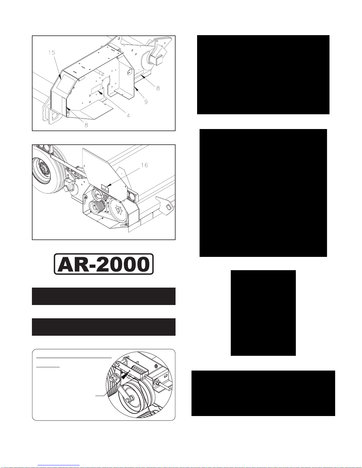
6 Decal Location
DECAL LOCATION
It is an owner’s and dealer’s responsibility to
ensure clear, complete decals are maintained
on equipment, whether operating or offered for
sale.
Information herein is provided for proper decal
ordering and placement.
Decal surfaces should be free of dirt, grease,
etc. Temperatures should be above 50° F. To ap-
ply, remove the smaller part of the decal backing
paper and apply this part of the exposed adhe-
sive to the desired location. Peel the other part
of the backing paper slowly off and smooth out
the entire decal.
15
7
3
2
81
14
PHOTO NO. ARS040A
11
PHOTO NO. DSCN4637B
14
3
2
2
20
PHOTO NO. ARS004A
17
6
10
12
5
19
21
PHOTO NO. 100-4282A
13
9
8
18
PHOTO NO. 100-4283A
Section 7
Decal Location 7
DWG NO. 6865
DWG NO. 6866
FIGURE 1 79202299 LOGO AR-2000
FIGURE 2 71505168 LOGO HINIKER
AR-2000
FIGURE 3 79202337 LOGO AR-2000
No Rotation. Read Operators Manual.
IMPORTANT: Maintain Belt Tension
Stop unit completely for maintenance.
Compress spring until
washer can be seen
through sight hole
PART NO. 79203548
FIGURE 4 79203548 IMPORTANT: MAINTAIN BELTS...
FIGURE 5 71504126 IMPORTANT: OPERATE MACHINE...
FIGURE 6 71504133 IMPORTANT: HITCH...
FIGURE 7 715-03174 IMPORTANT: LIFT...
FIGURE 8 850-001-285 TAPE YELLOW REFLECTOR
8 Decal Location
FIGURE 9 850-001-305 TAPE RED REFLECTOR
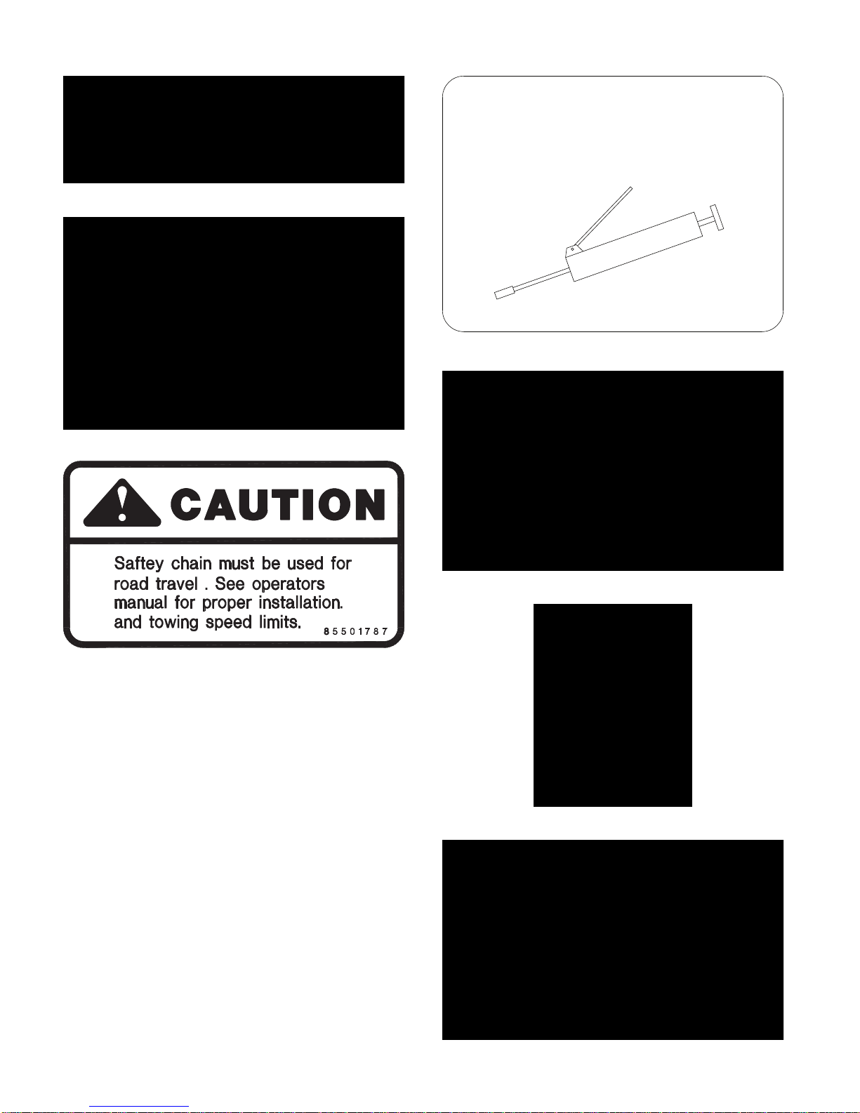
FIGURE 10 715-04132 CAUTION: READ MANUAL...
FIGURE 11 85501787 CAUTION: SAFETY CHAIN...
FIGURE 12 71504129 CAUTION: 1000 RPM
GREASE
FIGURE 13 79203259 GREASE:
FIGURE 14 71505169 WARNING: LOOK AND LISTEN...
FIGURE 15 71505171 WARNING: KEEP HANDS, ETC...
FIGURE 16 71505170 WARNING: DO NOT OPERATE...

Decal Location 9
FIGURE 17 520-03138 DANGER: ROTATING DRIVE...
FIGURE 18 520-03139 DANGER: SHIELD MISSING...
FIGURE 19 71504131 DANGER: KEEP FLIPPERS...
IMPORTANT
Maintain tires at 15-20 psi
on level land.
See operator's manual for
ridged operation.
71504136
FIGURE20 71504136 IMPORTANT: MAINTAINTIRES...
FIGURE 21 520-03138 WARNING: DO NOT EXCEED...

10 Section
TITLE
10 Field Preparation
WARNING: DEATH OR SERIOUS IN-
JURY CAN RESULT. BEFORE FIELD
PREPARATION, READ SAFETY-GEN-
ERAL, BEFORE OPERATION, DURING OP-
ERATION AND TOWING AT FRONT OF THIS
MANUAL.
TRACTOR-GENERAL
IMPORTANT: IT IS CRITICAL TO KNOW WHAT
SHREDDER CONFIGURATION IS INVOLVED
BEFORE TRACTOR HOOKUP. TRACTOR
MUST HAVE 1 3/4-20 SPLINE OUTPUT SHAFT.
Hiniker shredders are only available with a PTO
output option of: 1000 RPM 1 3/4”-20 spline
Part# 79202277
All units use ONLY CV (constant velocity) PTO’s.
These are identied by extended front yokes
separated by a large guide hub between them.
SHREDDER-TRAILING HITCH
Trailing shredders have an adjustable hitch
height adjustment (Item 1) to match various trac-
tor drawbar heights. Refer to Photo 100-4282B.
1
PHOTO NO. 100-4282B
IMPORTANT: CORRECT TRAILING HITCH
DRAFT LINK LENGTH ADJUSTMENT CAN-
NOT BE MADE UNTIL AFTER THE SHRED-
DER IS INITIALLY FIELDED.
FIELD PREPARATION
Raise the shredder with hitch jack until the hitch
yoke corresponds with the tractor’s drawbar and
insert hitch pin. Always store the hitch jack (ar-
row 1) as shown in Photo DCP0603.
1
PHOTO NO. DCP0603
IMPORTANT: ALWAYS USE A 1” DIAMETER
HITCH PIN.
CAUTION: DEATH OR SERIOUS IN-
JURY CAN RESULT. ALWAYS INSERT
THE HITCH PIN POINT DOWN WITH A
CROSS LOCKING PIN THROUGH ITS LOWER
END.
SHREDDER-PTO’s
IMPORTANT: IT IS CRITICAL TO KNOW WHAT
TRACTOR CONFIGURATION IS INVOLVED
BEFORE HOOKUP. THE PROPER SHREDDER
PTO MUST BE USED, OTHERWISE UNSAT-
ISFACTORY PERFORMANCE WILL RESULT.
TRACTOR MUST HAVE 1 3/4-20 SPLINE OUT-
PUT SHAFT.
All shredder PTO’s have similar sliding yoke
couplers at the tractor and gearbox ends. GEAR-
BOX ENDS ARE IDENTIFIED BY AN OVER-
RUNNING CLUTCH (Item 1).
Clean gearbox spline of any encrusted dirt or
grease and lightly oil it. Slide outer PTO collar
(Item 2) toward its adjacent yoke (Item 3) and
slide PTO over the gearbox spline. Reverse the
sliding collar to lock the assemblies together.

Field Preparation 11
PHOTO NO. 2969A
NOTICE: TO FACILITATE PTO HOOK UPS, CHECK
TRACTOR SPLINE FOR BURRS, OR OTHER DAM-
AGE. IF SHREDDER’S LOCKING COLLAR IS DIF-
FICULT TO PROPERLY ENGAGE, CLEAN AND
LIGHTLY OIL SPLINE.
The tractor PTO spline engages similar to above.
Slide outer collar (Item 1) toward its adjacent yoke
(Item 2) and slide PTO over the tractor spline. Re-
verse the sliding collar to lock the assemblies togeth-
er.
PHOTO NO. 2966A
WARNING: DEATH OR SERIOUS IN-
JURY CAN RESULT. NEVER OPERATE
A SHREDDER UNLESS BOTH ENDS
OF THE PTO ARE PROPERLY LOCKED TO
THEIR INTENDED SPLINES.
Check the decal on gearbox shield to insure
proper tractor/shredder RPM matching.
DWG. NO. 71504129
DANGER: DEATH OR SERIOUS IN-
JURY CAN RESULT. KEEP AWAY AND
KEEP OTHERS AWAY FROM AN OP-
ERATING PTO. DO NOT OPERATE WITH-
OUT ALL SHIELDS IN PLACE. INSURE PTO
SHIELDS FREE WHEEL AND BOTH PTO’S
ENDS ARE SECURELY ATTACHED.
IMPORTANT: NEVER TOW A TRAILING
SHREDDER UNLESS THE PTO IS PROPER-
LY HOOKED UP TO BOTH TRACTOR AND
SHREDDER. OTHERWISE, IT CAN BE DAM-
AGED. IF NECESSARY TO OTHERWISE TOW,
DETACH ENTIRE PTO ASSEMBLY (1) FROM
GEARBOX AND SECURE IT BEHIND A DRIVE
SHAFT SHIELD (2).
PHOTO NO. 3547
SHREDDER ROCKSHAFT & WHEELS
Toadjusttherockshafteldwheelspacingthe
end transport wheels can be used. Insert trac-
tor quick couplers to give machine a down-
ward movement when tractor hydraulic lever is
pushed forward.
12 Field Preparation
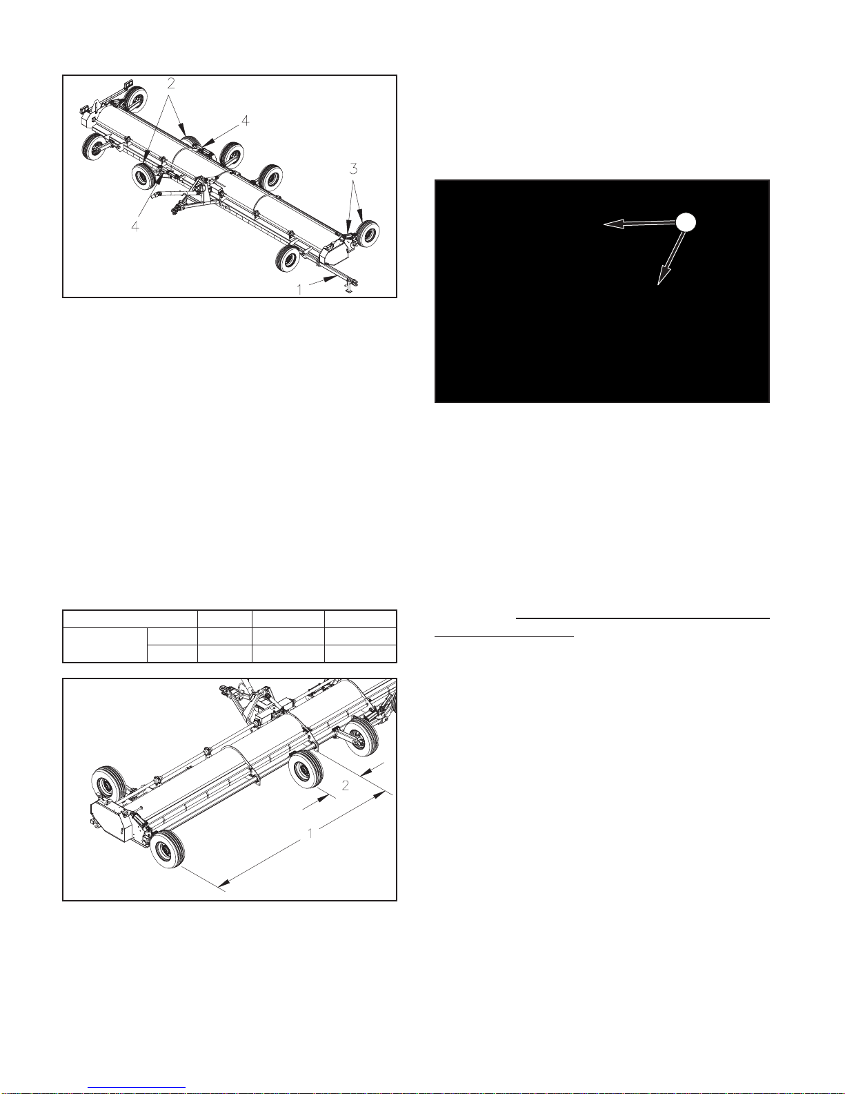
DWG NO. 6668
To adjust wheel spacing on rear rock shaft wheels,
attach a tractor of adequate size to operate unit
totheeldhitch.Slideendtransporthitchoutand
pin in position (arrow 1). Attach jack to spud on
hitch. Using tractor hydraulics lower end transport
wheels(arrow2)andraiseeldwheels(arrow3).
Rotate locking channels (arrow 4) over end trans-
port hydraulic cylinder shafts to prevent cylinder
contracting.
Loosen wheel bolt clamps and slide wheels into
correctdimensionsforeldoperation.Thecor-
rect spacing for 30” and 36” row and is provided
in the table below.
Dimns. 30” Rows 36” Rows
30 foot units (outer) (1) 180” 180”
(inner) (2) 30” 36”
DWG NO. 6667
For other row spacings, adjust the above set-
tings accordingly. Torque up each wheel leg
clamping bolts by uniformly tightening the lower
boltstoasnugt.Then,torque,andre-torque
top bolts to 146-206 Ft/lbs.
Once correct spacing is set up unlock end
transport cylinder locks. Lower eld wheels all
the way down. Raise end transport cylinders and
slide end transport hitch in and re-pin in position.
Store jack in its storage position.
1
PHOTO NO. 1000-4284A
Hydraulic cylinder control segments (arrow 1)
are provided to hold machine at desired cutting
height.
SHREDDER TIRES
Recommended tires are 9.5L x 15 8 ply
(implement) tires with 8” rims. The shredder
will perform better, especially under ridged
conditions, if tire pressures are kept no greater
than recommended. (If the shredder tends to
“yaw”, or climb ridged rows, decrease pressure
in the outside tires to the lower range cited and
recheck that tire centerlines are running in the
row middles.
SHREDDER-END TRANSPORT TOWING
Hiniker 30 Ft. shredders are designed for end
transport only down public roadways. Implement
lights (arrow 1) and SMV sign (arrow 2) are
standard equipment and mounted on rear of
machine.

Field Preparation 13
1
2
PHOTO NO. ARS048A
CAUTION: DEATH OR SERIOUS INJU-
RY CAN RESULT. WHEN TOWING ON
PUBLIC HIGHWAYS:
USE A TRACTOR OF SUFFICIENT SIZE, AND
WEIGHT, REQUIRED FOR FIELD OPERATION.
DO NOT TOW AT SPEEDS IN EXCESS OF 25
MPH (40 KMH).
USE A TOWING CHAIN BETWEEN TOWING
VEHICLE AND SHREDDER.
THE SMV’S REFLECTIVE SURFACE MUST
BE VISIBLE FROM THE REAR OF UNIT.
CHECK LOCAL REGULATIONS ON TOWING
WIDTH AND WARNING LIGHTS.
THE FRONT HITCH, PTO AND PTO HOLDER
MAY BE REMOVED TO REDUCE THE END
TRANSPORT WIDTH IF REQUIRED.
Use a safety towing chain (Item 1) between the
shredder and towing vehicle. Hook chain around
bracket (Item 2) and pass forward through after-
market clevis (Item 3). Fix chain’s forward end
(Item 4) to tractor.
PHOTO NO. 3550
Checkthelightstobesuretheyareconnectedprop-
erlysothatturnsignalashersoperatecorrectly.

14 Section
TITLE
OPERATION
WARNING: DEATH OR SERIOUS IN-
JURY CAN RESULT. BEFORE OPER-
ATING, READ SAFETY-GENERAL,
BEFORE OPERATION, DURING OPERATING
AND TOWING AT FRONT OF THIS MANUAL.
GENERAL
DWG. NO. 71504131
DWG. NO. 71504132
Always operate tractor at standard 1000 RPM
PTO. Use transmission up, or down, shift to
vary forward speed. CONSISTENTLY OVER-
SPEEDING THE PTO WASTES FUELAND AG-
GRAVATES KNIFE WEAR.
Avoid “jackrabbit” PTO engagement at full speed
because it overstresses the shredder’s driveline.
Engage PTO at slow speed and throttle up to
operating speed.
Insert quick couplers to give shredder a DOWN-
WARD movement when tractor hydraulic lever is
shoved FORWARD and vice versa.
IMPORTANT: FOR TRAILING HITCH END
TURNS ACROSS RIDGED ROWS, SLOW
FORWARD SPEED AND RAISE MACHINE
TO MINIMIZE EXCESSIVE BOUNCING AND
SCALPING.
CAUTION: DEATH OR SERIOUS INJURY CAN
RESULT. FOR TRAILING UNITS, SOME
TRACTOR MASTER PTO SHIELD’S
MAY CONTACT SHREDDER’S FRONT
PTO SHIELD ON TURNS. BE ALERT FOR
THIS AND MAXIMIZE TURNING RADII. RE-
PLACE SHREDDER FRONT PTO SHIELD IF IT
BECOMES DAMAGED.
IMPORTANT: INITIALLY START SHREDDING
WITH UNIT SET SUBSTANTIALLY HIGHER
THAN THE RECOMMENDED MINIMUM KNIFE/
ROW CLEARANCE OF 3”.
Shred a short distance and check performance.
The higher knife/row clearance may not give sat-
isfactory results; therefore, lower unit and check
again. Progressively lower unit until good results
are obtained. DO NOT OPERATE WITH LESS
THAN 3” KNIFE CLEARANCE TO HIGHEST
GROUND POINT WITHIN SHREDDED WIDTH.
Once optimum height is set, insert equal amount
of hydraulic cylinder stop segments over the
rods of the lift cylinders to hold machine at de-
sired height.
IMPORTANT: “SCALPING” ROWS WASTES
FUEL AND RAPIDLY AGGRAVATES KNIFE
WEAR. THIS IS PARTICULARLY TRUE IN
ROCKY FIELDS. IF YOUR FIELD HAS PRO-
TRUDING ROCKS, KEEP UNIT’S HEIGHT
SUFFICIENT FOR KNIVES TO CLEAR THEM.
STALK SHREDDERS ARE NOT INTENDED TO
BE USED AS A “ROCK PICKER”, OR A “RO-
TOTILLER”.
Operate the shredder approximately LEVEL.
That is, front (Item 1) of main frame should clear
ground about the same as the rear (Item 2).
14 Operation
Operation 15
CAUTION: DEATH OR SERIOUS
INJURY CAN RESULT. EXCESSIVE
FRONTFRAME/GROUNDCLEARANCE
CAUSES MORE DEBRIS TO THROW
FORWARD UNDER THE TRASH SHIELDS.
NEVER STAND NEAR, AND AHEAD OF, A
RUNNING MACHINE.
DWG NO. 6869
TRAILING HITCH HEIGHT ADJUSTMENT
1. Position unit astraddle rows and insure
wheels are centered in row middles before
making any adjustments. Rotate
rockshaft/wheels until knives clear rows by
GREATER than 3”.
1
PHOTO NO. 100-4277A
With unit attached to tractor, adjust turn-
buckle (arrow 1) to raise machine front up
or down to desired height.
2. Recheck knives/row clearance and read-
just rockshaft/wheels, as well as draft link
length, if necessary.
3. Shred a short distance, stop and check
stubble to insure knives are properly clear-
ing rows and satisfactory performance is ob-
tained. If necessary, reset rockshaft/wheels
and drawbar’s underneath draft link.
4. Ensure cylinder stop collars, are of equal
height on lift cylinders.
END TRANSPORT TOWING
The 30 Ft. AR shredder can only be towed down
public highways in end transport mode. Towing
theshredderineldmodedownpublichighways
will violate local regulations and is prohibited.
CAUTION: DEATH OR SERIOUS INJU-
RY CAN RESULT. WHEN TOWING ON
PUBLIC HIGHWAYS:
USE A TRACTOR OF SUFFICIENT SIZE, AND
WEIGHT, REQUIRED FOR FIELD OPERATION.
DO NOT TOW AT SPEEDS IN EXCESS OF 25
MPH (40 KMH).
USE THE PROVIDED SAFETY TOWING
CHAIN BETWEEN TOWING VEHICLE AND
SHREDDER/WINDROWER.
USE THE SMV EMBLEM AS SPECIFIED AND
STORE PTO SHAFT IN PTO HOLDER.
CHECK LOCAL REGULATIONS ON TOWING
WIDTH AND WARNING LIGHTS.
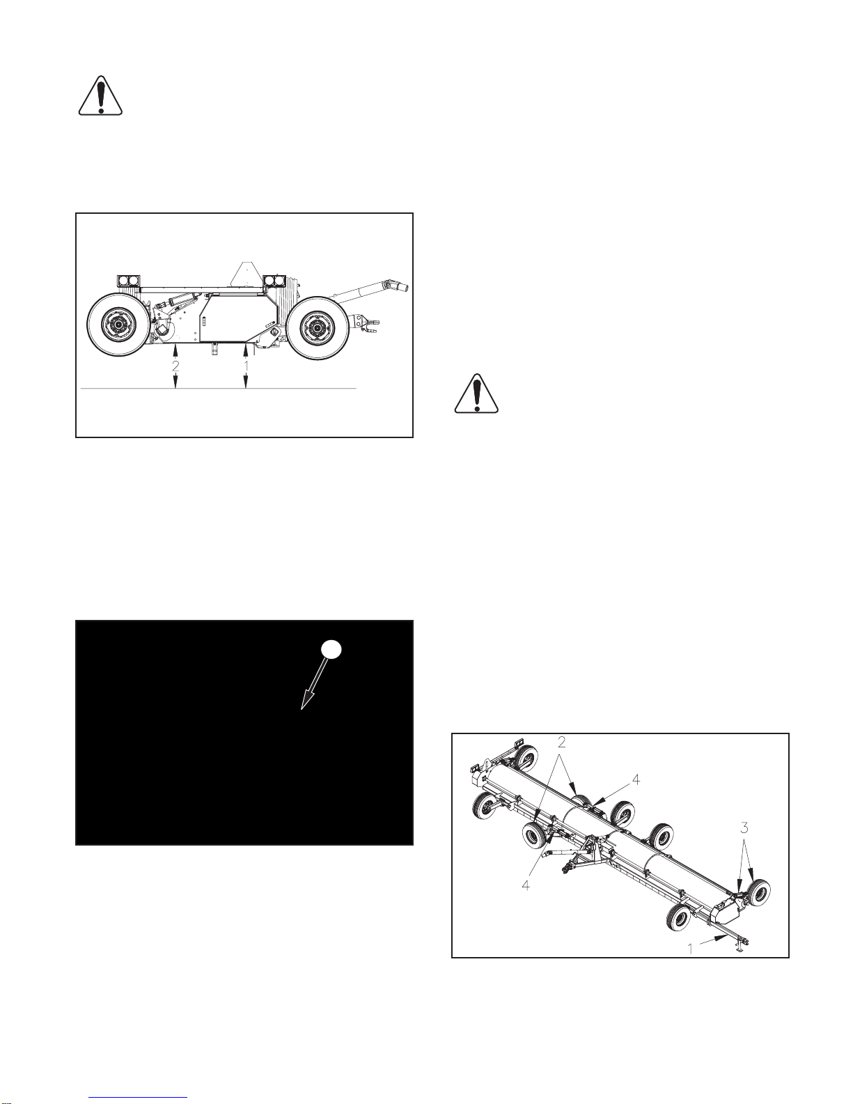
DWG NO. 6868
To put the machine in end transport. With tractor
attachedtotheeldhitchSlideoutendtransport
tongue (arrow 1) and pin in position.

Rotate jack into position. Lower end transport
wheelsall the way down (arrow2). Raise eld
wheels all the way up (arrow 3). Rotate hydraulic
cylinder channel locks (arrow 4) into position to
hold cylinders in the fully extended position. Us-
ing jack raise front end of tractor until the cast
hitch on shredder comes off the draw bar of the
tractor.
DWG NO. 6870
Disconnect hydraulic lines and store in hydrau-
lic tip holder (arrow 5). Flip up PTO holder (ar-
row 6). Disconnect PTO and lay in PTO holder.
Raise or lower end transport hitch so it can be
attached to tractor drawbar.Attach tractor of suf-
cientsizeforoperationtoendtransporttongue.
Storejackoneldhitchstoragelocation.
DWG NO. 6871
Wrap safety Chain around hitch tube and pass
through the large chain end loop and welded on
c-channel.
2
1
PHOTO NO. 3550B
Attach safety chain on end transport hitch to
tractor.
Insert electrical connector into tractor. Verify
warning lights and turn indicators all work cor-
rectly. Verify SMV sign is visible from rear of ma-
chine.
STORAGE
CAUTION: DEATH OR SERIOUS
INJURY CAN RESULT. DISENGAGE
PTO, STOP TRACTOR ENGINE,
SET BRAKES, REMOVE KEY AND ALLOW
EQUIPMENT TO COME TO A COMPLETE
STOP BEFORE:
CLEANING, UNCLOGGING, LUBRICATING,
INSPECTING, OR OTHERWISE SERVICING,
ANY PART OF THIS EQUIPMENT.
The following will insure equipment is in top
operating condition at start of next season.
1. Open end shields and thoroughly clean
out dirt and trash. Clean out any other
trash hanging on unit. Check drive shaft
and gearbox bearing seals for trash
entanglement.
2. Back off backwrap belt idlers to relax tension
on “V” belts. Inspect belts for wear.
3. Clean debris from PTO ends and insure
safety shield freely rotates.
16 Operation

Operation 17
4. Relube machine and check gearbox lube
level.
5. Clean rust off exposed surfaces and repaint
any surface requiring it. Also check for any
loose hardware.
6. Inspect both rotor assemblies for lost,
broken, or worn out knives. Replace
these as required. Also, replace any other
deteriorated parts, especially decals and
reectors.

18 Section
TITLE
LUBRICATION
WARNING: DEATH OR SERIOUS INJU-
RY CAN RESULT. BEFORE LUBRICAT-
ING, READ SAFETY-GENERAL AND
SERVICE AT FRONT OF THIS MANUAL.
CAUTION: DEATH OR SERIOUS IN-
JURY CAN RESULT. DISENGAGE PTO,
STOP TRACTOR ENGINE, REMOVE
KEY AND ALLOW EQUIPMENT TO COME TO
A COMPLETE STOP BEFORE: CLEANING,
UNCLOGGING, LUBRICATING, INSPECTING,
OR OTHERWISE SERVICING, ANY PART OF
THIS EQUIPMENT. SECURELY BLOCK UNIT
BEFORE SERVICING TO PREVENT UNEX-
PECTED FALLING.
HINIKER shredders have been factory checked
and lubricated. However, re-check and relubri-
cateaunitpriortorsteldoperation.
Shredders operate in an extremely dirty (ne
dust) environment. Proper maintenance atten-
tion to the anti-friction bearings will save money!
IMPORTANT: WIPE ALL ZERKS AND GUN
TIPS BEFORE LUBRICATING.
IMPORTANT: WHEN LUBRICATING BEAR-
INGS ADHERE TO 1 PUMP PER FITTING ON
A DAILY INTERVAL.
When lubricating, couplers, pivots, and PTO lu-
bricate until you see grease. Items (8 & 15) CV
double yoke needs 15 to 20 pumps.
IMPORTANT: INNER ROTOR COUPLER (ITEM
29) NEEDS 20-25 PUMPS DAILY FOR PROP-
ER OPERATION.
Replace any damaged ttings and use a good
grade of lithium base grease.
Gearbox should be checked at least seasonally.
After300hoursoperation,drainandrell.
A 1000 rpm gearbox is checked by measuring
3 7/8” to 4” depth to lube level below ll hole
thread top or use check plug at rear. Clean plug
before removing. Use a.P.I. 80W90 synthetic ex-
treme pressure lubricant.
Lubrication Chart
Ref.
No. Description Interval
1. Front Cross & Bearing Daily
2. Front Shield Bearing Daily
3. Sliding Tube Daily
4. Rear Shield Bearing Daily
5. Rear Cross & Bearing Daily
6. Overrunning Clutch Daily
7. Front Shield Bearing Daily
8. CV Cross Daily
9. CV Cone Shield & Bearing Daily
10. Front Cross & Bearing Daily
11. End Transport Pivot Daily
12. Overrunning Clutch Daily
13. Rear Cross & Bearing Daily
14. Rear Shield Bearing Daily
15. CV Flange (15-20 Pumps) Daily
16. Line Shaft Coupler (15-20 Pumps) Daily
17. Outer Rotor Bearing Daily
18. Rockshaft Bearing Weekly
19. Center Bearings Daily
20. Wheel Hub Weekly
21. Ratchet Jack Seasonal
22. Gearbox Drain 300 Hours
23. Center Rotor Bearings Daily
24. Outer Lineshaft Bearing Daily
25. Mid Lineshaft Bearing Daily
26. Idler Pivot Weekly
27. Gearbox Breather -----------
28. Gearbox Oil Level Check Plug -----------
29. Rotor Coupler (20-25 Pumps) Daily
18 Lubrication
Other manuals for AR-2000
1
Table of contents
Other Hiniker Paper Shredder manuals


