Hinterberg Design Machine quilting frame User manual

1
YOU WILL NEED TO PURCHASE:
5 pieces of 1-1/4” thin wall metal conduit (EMT) cut to your preferred
length for the rollers. (Maximum 120”)
DETERMINING YOUR ROLLER LENGTH:
Determine the width of the widest quilt you would like to make on the
frame. Add min. 8” to that width for your final roller length. The extra 8” allows
for extra room for your machine at the sides of the quilt. You also may want to
have an open space at the end of your frame to wheel your machine out from
under the quilt for maintenance.
If you would like to have 2 sets of rollers, we have a hardware package
available. Please call (319) 378-0999 or visit our website at
www.hinterberg.com.
OPTIONAL TEMPLATE SURFACE:
A 1/2” x 8” pine board, cut 1-½” longer than your roller length can be used
for a template board surface.
Pre-patterned grooved template boards are available from us at an addi-
tional cost. Board length fits 10’ rollers. A 1/2” x 8” pine board is required to
support the grooved template board.
STAINING & FINISHING:
Applying a stain and finish to the frame is optional. It will not harm it to
leave it unfinished. If you wish to stain or finish your frame, it is easier to do
before you assemble it. What stain you use depends on your own prefer-
ence, but we recommend using a penetrating oil base wipe-on stain or a
combination stain/polyurethane for best results. Since there are moving
parts on your frame, we do not recommend any finish like varnish or shel-
lac that build up on the surface of the wood.
Please see our website www.hinterberg.com or call (319) 378-0999
Revised 10/08
MACHINE QUILTING FRAME

2
MACHINE QUILTING FRAME
BACK
FRONT

3
HARDWARE
Height Adjuster
3111 Roller End Insert
3057 1/4” Machine Screw
3028 1-1/4” Wood Screw
3056 1-1/4” Lag Screw
3047 1-1/2” Lag Screw
3053 1/4” Hex Head Bolt
3041 1/4” Allen Head Bolt
3054 2” Carriage Bolt
3022
3/8” Metal
Washer
3037
Plastic
Washer
3021
1/4” Metal
Washer
3043 Allen Wrench
3045 J-Hook
3031 Barrel Nut
3032 1/4” Wing Nut
3018 3/8” Wing Nut
3029 Hex Nut
3049 Hex Wrench
3112
T-Knob w/ 5/8” stud 3113
T-Knob w/ 1-1/8” stud 3106
Star Knob w/ stud 3076
Star Knob

4
Carriage Handle Hardware
DESCRIPTION PART# QTY.
Knobs with Short 5/8” studs 3112 2
Knob with Long 1 1/8” stud 3113 1
Machine Screws 1/4” x 3/4” 3057 3
Plastic Washer 3037 1
Carriage Handle Parts
U - Shaped Handle 2041 1
T - Shaped Handle 2042 1
I - Shaped Handle 2043 1
L - Shaped Handle 2044 1
End Frame Hardware
DESCRIPTION PART# QTY.
Height Adjuster Assemblies 4
1/4” x 1-1/4” Hex Head Screws 3056 8
1/4” Metal Washers 3021 11
1/4” x 1-1/2” Hex Head Screws 3047 3
Small Plastic Washers 3037 3
Large Black Star Knobs 3076 14
3/8” x 2” Carriage Bolts 3054 4
Phillips Head Wood Screws 1 1/4” 3028 12
Lock Pins 3105 4
Teflon Tape 9029 8
MACHINE FRAME HARDWARE
Center Support Hardware
DESCRIPTION PART# QTY.
J-Hook 3045 4
Allen Head Bolt 3041 4
3/8”x2” Carriage Bolt 3054 1
3/8” Metal Washer 3022 1
1/4” Metal Washer 3021 4
1/4” Wing Nut 3032 4
3/8” Wing Nut 3018 1
Barrel Nut 3031 4
Allen Wrench 3043 1
Pointer Package Hardware — Included, see page 19
Leg Brace Hardware
DESCRIPTION PART# QTY.
Black Star Knob with Stud 3106 4
3/8” Hex Nut 3029 4
J-Hook 3045 8
1/4” Metal Washer 3021 8
1/4” Wing Nut 3032 8
Roller End Hardware
DESCRIPTION PART# QTY.
Barrel Nuts 3031 3
1/4” Metal Washers 3021 3
1/4” x 1 1/2” Hex Head Bolts 3053 3
Hex Head Wrench 3049 1
Metal Roller Inserts w/ 3” bolts 3111 10
Tools Required
Phillipshead screwdriver
Hammer

5
WOOD PARTS
A B
C D
E F
G
H
G
H
I J
K L
M
N
O P
Q
R
S
T
U V
W
X
Y
Z

6
Part # Qty.
A Left End Frame 4031 1
B Right End Frame 4030 1
C Front left roller support guide 4025 1
D Front right roller support guide 4026 1
E Right template support 4028 1
F Left template support 4029 1
G Angle brace 1 4056 2
H Angle brace 2 4057 2
I Middle roller support guide 4027 2
J Ratchet Wheels 4017 3
K Left rear roller support 4006 1
L Left middle roller support 4032 1
M Left spacer 4012 1
N Left front roller support 4016 1
O Right middle roller support 4033 1
P Right rear roller support 4005 1
Q Right spacer 4011 1
R Right front roller support 4015 1
S Pawl 4013 2
T Pawl 4014 1
U Upper Carriage MQF UC 1
V Lower Carriage MQF LC 1
W Top support w/ square hole 4077 1
X Top support w/ round hole 4078 1
Y Center Support Roller Bracket 4076 2
Z Center Support Upright 4083 1
MACHINE FRAME WOOD PARTS LIST

7
END FRAME ASSEMBLY INSTRUCTIONS
Locate bag of hardware labeled “End Frame Hardware”
STEP 1.
Assembling Front Roller Supports
Use 1 1/4” Phillips head wood screws to
attach the spacers to the front roller sup-
ports, matching slots and pre drilled holes.
See Fig. 1
STEP 2.
Attaching the Pawls
The pawls are only attached to the right
spacer and the right middle and right rear
roller supports. Insert a hex head screw
(in small bag) and metal washer through
the ratchet pawl as shown in Fig. 2. The
small plastic washer, goes between the
pawl and the pole support to make the
pawl work smoothly. Tighten the screw so
the pawl swings easily. You will need to
use either a 7/16” wrench or the Hex
Head Wrench found in the bag labeled
“Roller End Hardware”. See Fig 2a and 2b
for correct placement of the pawls.
FIG. 2
PAWL
FRONT
ROLLER
SUPPORT
FIG. 1
RIGHT FRONT ROLLER
SUPPORT RIGHT SPACER
LEFT FRONT ROLLER SUPPORT
LEFT
SPACER
FIG. 2a
PAWL
FIG. 2b
8
STEP 3.
Template Support
Locate the right end frame and the right tem-
plate support. Both inside and outside edges
of the end frames are rounded over. The
template supports are only rounded over on
one edge. The flat side goes against the end
frame for a close fit.
Lay the end frame on a flat surface and at-
tach the right-hand template board support
with four 1 1/4” Phillips head wood screws.
See Fig 3.
TEMPLATE SUPPORT
FIG. 3
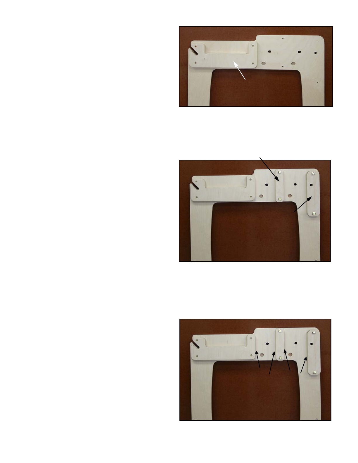
STEP 4.
Roller Support Guide
Locate the right front roller support guide and
the right middle roller support guide and lay
them on the right end frame as shown. See
Fig. 4. The purpose of the rectangular
guides is to keep the middle and rear roller
supports aligned vertically.
As with the template support, the side of the
guide without the rounded edge lies against
the end frame. The large hole in the front
support should line up with the hole in the
end frame.
You will be attaching the guides to the end
frame with (4) 1/4” x 1-1/4” hex head
screws. Place a 1/4” steel washer onto the
screw. Insert the hex head screw through
the guide, and then screw into the end frame
loosely. The screws will be tightened after
attaching the roller supports. There is a
wrench included in the “roller end hardware”
bag, that can be used for these screws.
STEP 5.
To Prevent Roller Supports From Sticking
In the ’End Frame Hardware bag’ you will
find blue strips of Teflon tape. These are ac-
tually clear strips of Teflon tape with blue
backing. Remove the blue backing and apply
the strips of tape to the wooden parts before
assembly. See Fig. 5
Apply 3 1/2" strip of Teflon tape to edge of
template support.
Apply 5" strip of Teflon tape to both edges of
middle roller support guide.
Apply 6" strip of Teflon tape to edge of front
roller support guide.
This tape will allow the wooden parts to
glide smoothly past each other when rais-
ing and lowering the roller supports. FIG. 5
FRONT ROLLER
SUPPORT GUIDE
FRONT
OF
FRAME
REAR
OF
FRAME
FIG. 4
MIDDLE ROLLER
SUPPORT GUIDE
3 1/2”
5” 5” 6”

9
STEP 6.
Height Adjusters
Lay the right side end frame on a flat sur-
face. Locate the height adjuster assemblies.
Lay two height adjuster bolts into the slots in
the end frame. (The hole is slightly oval to
allow for minor variations in wood.) Notice
the hole in the barrel nut is off center. The
smaller end faces outward (towards you).
See Fig 6.
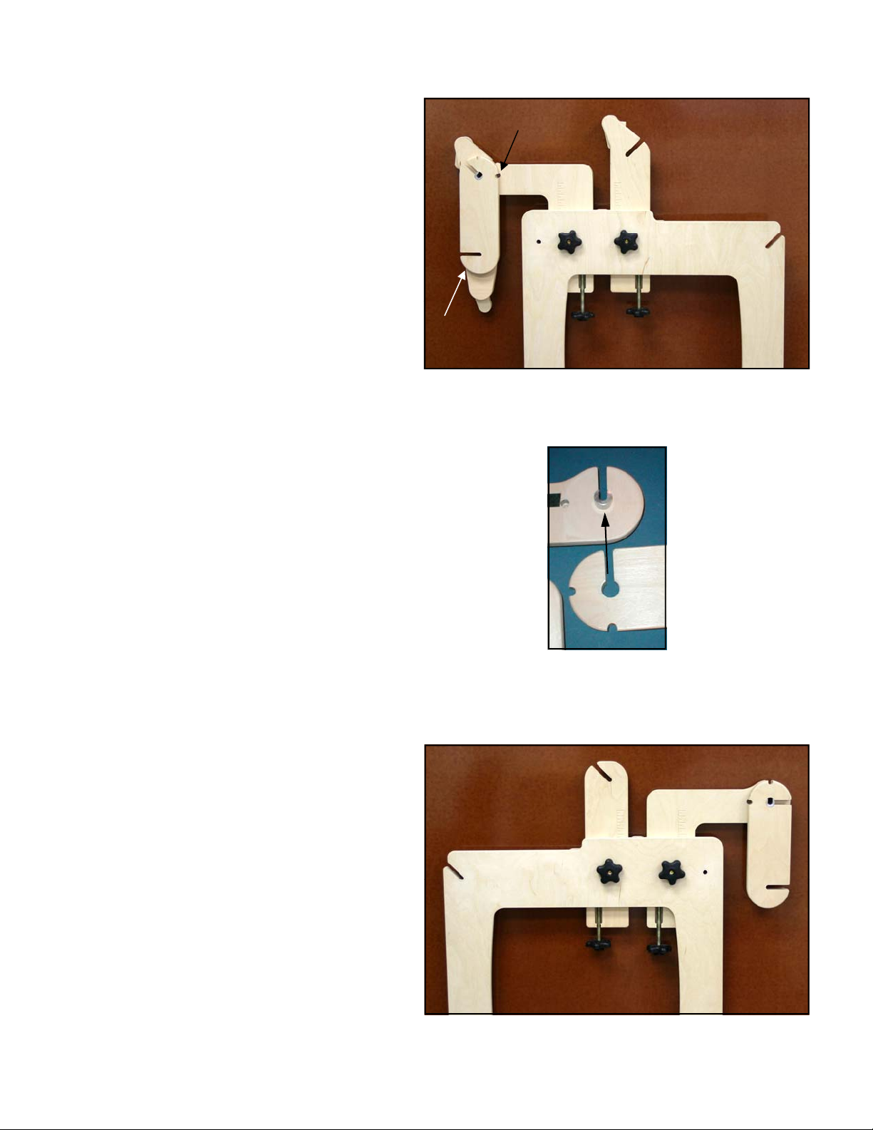
STEP 7.
Assembling Roller Supports
Holding the rear roller support in your hand,
flip it over and place it as shown in Fig 7.
Now the height adjuster is sandwiched be-
tween the end frame and the roller support.
Tighten the screws evenly in the middle
roller support guide, easing the guide toward
the rear support.
Repeat with middle roller support. Tighten
the screws evenly in the front support guide,
easing the guide toward the middle roller
support.
The first time you use the height adjuster
screws, you will need to turn the screws until
they pull themselves all the way up into the
roller support. They will be a little bit loose in
the grooves. This is normal and will not af-
fect their function.
FIG. 7
Rear Middle
FIG. 6
10
STEP 8.
Attaching Roller Supports
Insert a 2” carriage bolt through the hole in
the slot in each roller support and through
the corresponding hole in the end frame.
The square base of the head of the bolt
should sit down in the slot. Lift up the end
frame slightly and screw a black knob onto
this bolt from the outside of the frame to
hold it in place. See Fig 8.
STEP 9.
Front Roller Support Assembly
To attach the front roller support to the
middle roller support. Insert the aluminum
bearing (attached to the middle roller sup-
port) into the large hole in front roller sup-
port. See Fig. 9.
Insert a lock pin as shown in Fig. 8 to hold
front roller support in either the up or down
position.
Fig. 8 shows the outside view of the com-
pleted right side end frame.
FIG. 9
STEP 10.
Left Hand End Frame Assembly
The left hand roller supports and guides
are attached in the same manner as the
right.
Repeat steps 3 through 9 to complete
the left hand end frame assembly. Fig
10 shows the completed outside view of
the left end frame.
FIG. 8
Insert Lock Pin
Here
Left front roller
support
(See step 9)
FIG. 10

11
ROLLER END ASSEMBLY INSTRUCTIONS
Locate bag of hardware labeled “Roller End Hardware”
NOTE:
If, in the future you wish to make your frame longer or shorter, you can order additional
metal inserts and required hardware to build additional rollers and carriage tracks. Call
us at (319) 378-0999 for details
FIG. 1
STEP 1.
Inserting Metal Roller Ends
Tap the inserts into the end of the metal
rollers evenly with a hammer. Don’t tap
on the end of the bolt, because you may
damage the threads. Tap around the
edges of the silver round end. If it goes in
unevenly at first, keep tapping, it should
straighten itself out as it goes in. The
metal edges of the insert should be
seated on the ends of the roller. If the
roller ends are rough, you can file them
down. Repeat until all rollers have inserts
on both ends. See Fig. 1 & 2
FIG. 2
12
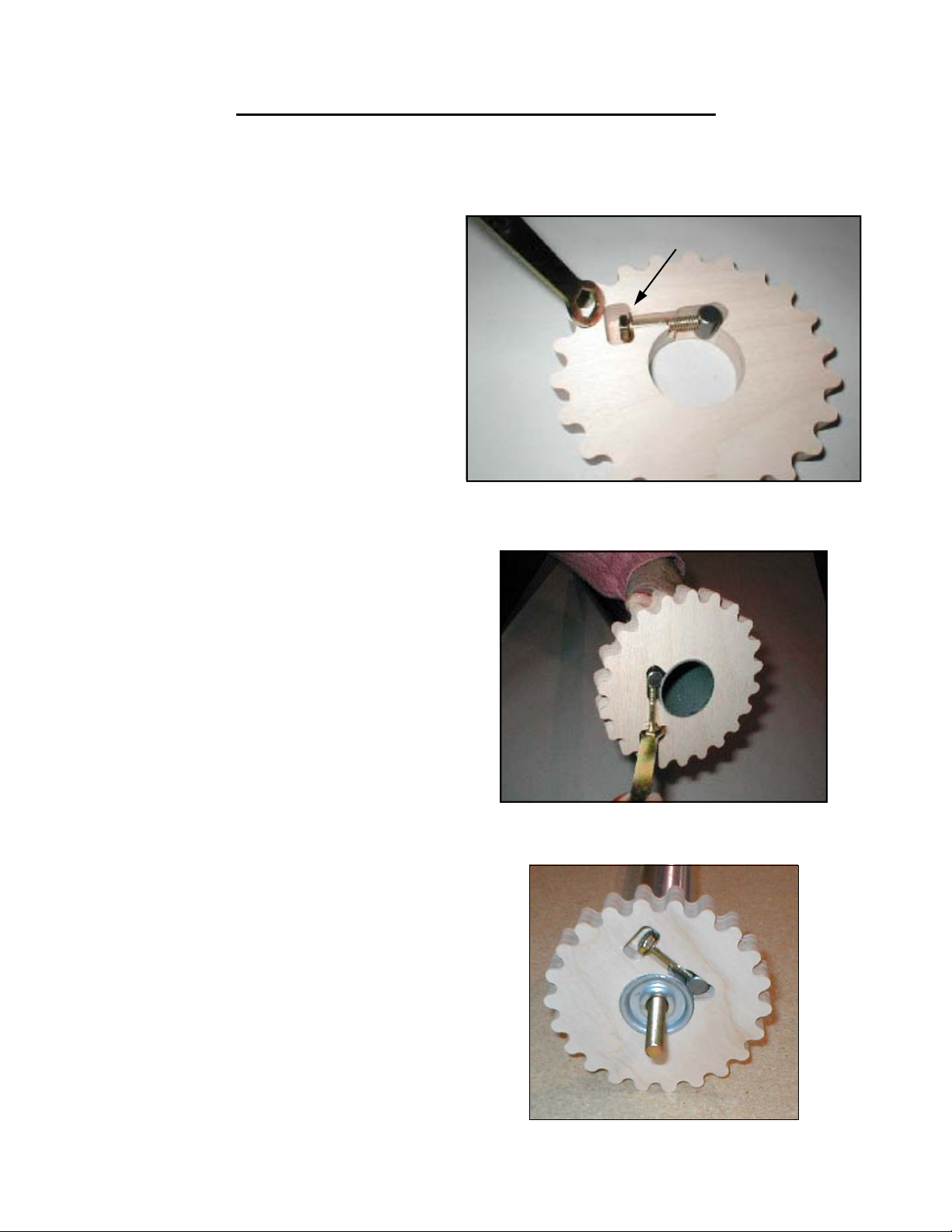
STEP 2.
Attaching Ratchet Wheels to Poles
Slide the ratchet wheel onto the end of the
conduit. The wheel should be flush with the
end of the conduit. If the edges of the con-
duit are a little rough you will want to file
them smooth for easier assembly. Tighten
the hex head bolt using the hex head
wrench provided. See Fig. 2. Just snug it
up so the bolt assembly doesn’t fall out.
Repeat steps 1 and 2 to attach ratchet
wheels loosely to the ends of 3 of the con-
duit rollers.
STEP 1.
Assembling Ratchet Wheels
The 3 ratchet wheels will be attached to
the right end of 3 of the conduit rollers.
Using the hardware found in the ‘roller
end hardware’ bag, slip the 1/4” washer
onto the hex head bolt and then screw
the hex head bolt into the barrel nut only
about 3 or 4 turns. Lay the bolt assem-
bly into the pocket in the ratchet wheel.
See Fig 1. The bolt assembly must lay
flat inside the pocket or it could rub
against the inside of the end frame.
FIG. 2
FIG. 1
WASHER
STEP 3.
Tightening the Roller Ends
Tighten all three ratchet wheels onto the
conduit. See Fig. 3.
FIG. 3
RATCHET WHEEL ASSEMBLY INSTRUCTIONS
Locate bag of hardware labeled “Roller End Hardware”
13
STEP 1.
Attaching the Carriage Tracks
Before attaching the leg braces to the
end frames, You will need to attach
the end frames and the carriage
tracks. To do this, stand both end
frames up and insert the front car-
riage track through the hole in each
end frame. Slide the rear carriage
track into the slots in the rear of the
end frames. See Fig 1. Screw a
black star knob onto all of the roller
end bolts loosely.
FIG. 1
REAR
OF
FRAME
FRONT
OF
FRAME
ATTACHING CARRIAGE TRACKS INSTRUCTIONS
14
FIG. 2
LEG BRACE ASSEMBLY INSTRUCTIONS
Locate bag of hardware labeled “Leg Brace Hardware”
FIG. 1
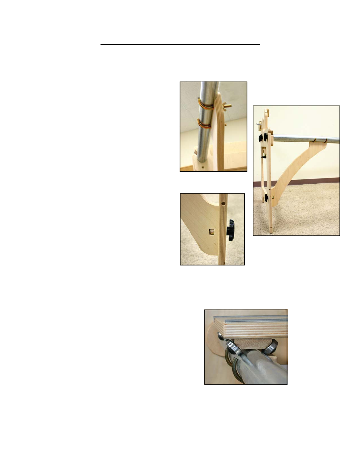
STEP 1.
Angle Brace Assembly
Locate the (4) angle braces. The angle
braces anchor the carriage track to the end
frames. This provides stability for the
whole frame.
The angle brace is designed to hold the
roller support with the J-hook bolts. The J-
hooks are used to secure the angle braces
to the front carriage support roller and the
rear carriage support roller.
Place the leg brace on carriage track as
shown in Fig. 1. Insert a J-hook bolt thru
the hole in the angle support and secure
with a small washer and a wing nut on the
inside of the frame.
The other end of the angle brace attaches
to the end frame. Insert a large hex nut in
the slot in the end of the angle brace.
Screw the black knob with post through the
end frame into the nut. This will secure the
angle brace to the end frame. See Fig 2 &
3.
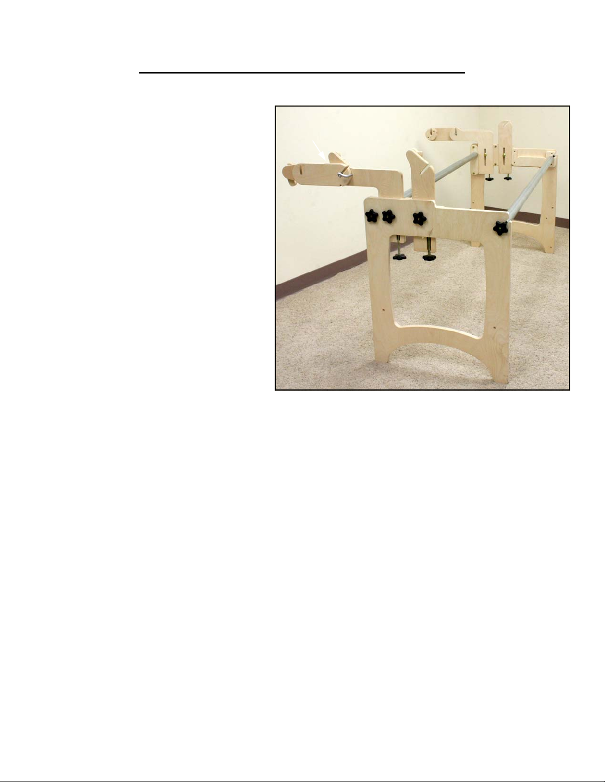
STEP 2.
Place Carriages on Rollers
Place the lower carriage onto the rollers
The double wheel assembly (See Fig.4)
sits on the front roller.
As you can see from the picture, the J-
hook bolts are designed to clear the wheel
assembly. If you are having trouble with
your carriage hitting the J-hook bolts, you
may have your carriage on the frame back-
wards.
Place your upper carriage onto the lower
carriage. FIG. 4
FIG. 3

15
Step 2. Lock Pins
Two more lock pins are used to hold the
front roller in its slot while it is in the down
position. They are inserted thru a square
hole in the front spacer Fig 2. shows the
lock pin location, the pole is not pictured.
Remove the lock pins before attaching the
roller to the end frames. FIG. 2 ROLLER SITS HERE
STEP 1.
Assembling the Rollers
Set each of the end frames so that the
front roller support is in the ‘up’ position.
Set each of the 3 conduit rollers into the
slots in the end frame. All of the ratchet
wheels should be on the right hand side
of the frame.
Screw a black star knob onto all of the
roller end bolts loosely.
During quilting, the pawls will catch the
ratchet wheels and prevent them from
turning in order to keep tension on your
quilt.
See Fig 1 for roller locations.
NOTE:
Fig 1 shows strips of fabric attached to the rollers. Your quilt layers will be pinned to this fabric.
You can provide your own fabric for this purpose or you can order it pre-cut and serged from
us. Call us at (319) 378-0999 for details.
REAR MIDDLE
FRONT
FIG. 1
ROLLER ASSEMBLY INSTRUCTIONS

16
CENTER SUPPORT INSTRUCTIONS
Locate bag of hardware labeled “Center Support Hardware”
STEP 2.
Insert the carriage bolt through the
hole. The square head of the carriage
bolt should sit in the square hole in the
top support. See Fig. 3. Flip the center
support assembly over and secure car-
riage bolt with 3/8” washer and wing-
nut. See Fig. 4.
FIG. 3
STEP 3.
To attach roller brackets, insert barrel nut
into the holes on the side of the top support.
See Fig. 5.
FIG. 4
FIG. 5
STEP 1.
Lay the Center support up-
right in the pocket in the Top
support w/ round hole. See
Fig. 1
Lay the Top support with the
square hole on top of the
other two parts as shown in
Fig. 2.
FIG. 2
FIG. 1
FRONT REAR
FRONT REAR

17
FIG. 6
Scoop on top
STEP 4.
Insert allen head bolts through roller bracket.
The scoop on the roller bracket is located
towards the top of the center support. See
Fig. 6.
Use four barrel nuts and allen head screws
to attach the roller brackets to each end of
the top supports.
FRONT
REAR
ASSEMBLED CENTER SUPPORT
STEP 5.
Make sure the front and rear of the center
support are oriented correctly. See com-
pleted picture below.
Attach the center support to the two carriage
rollers using the J-hook screws. Secure the
J-hook screws using a 1/4” washer and wing
nuts. See Fig. 7
Using all 4 J-hook screws, attach both ends
of the center support to both of the carriage
track rollers. FIG. 7

18
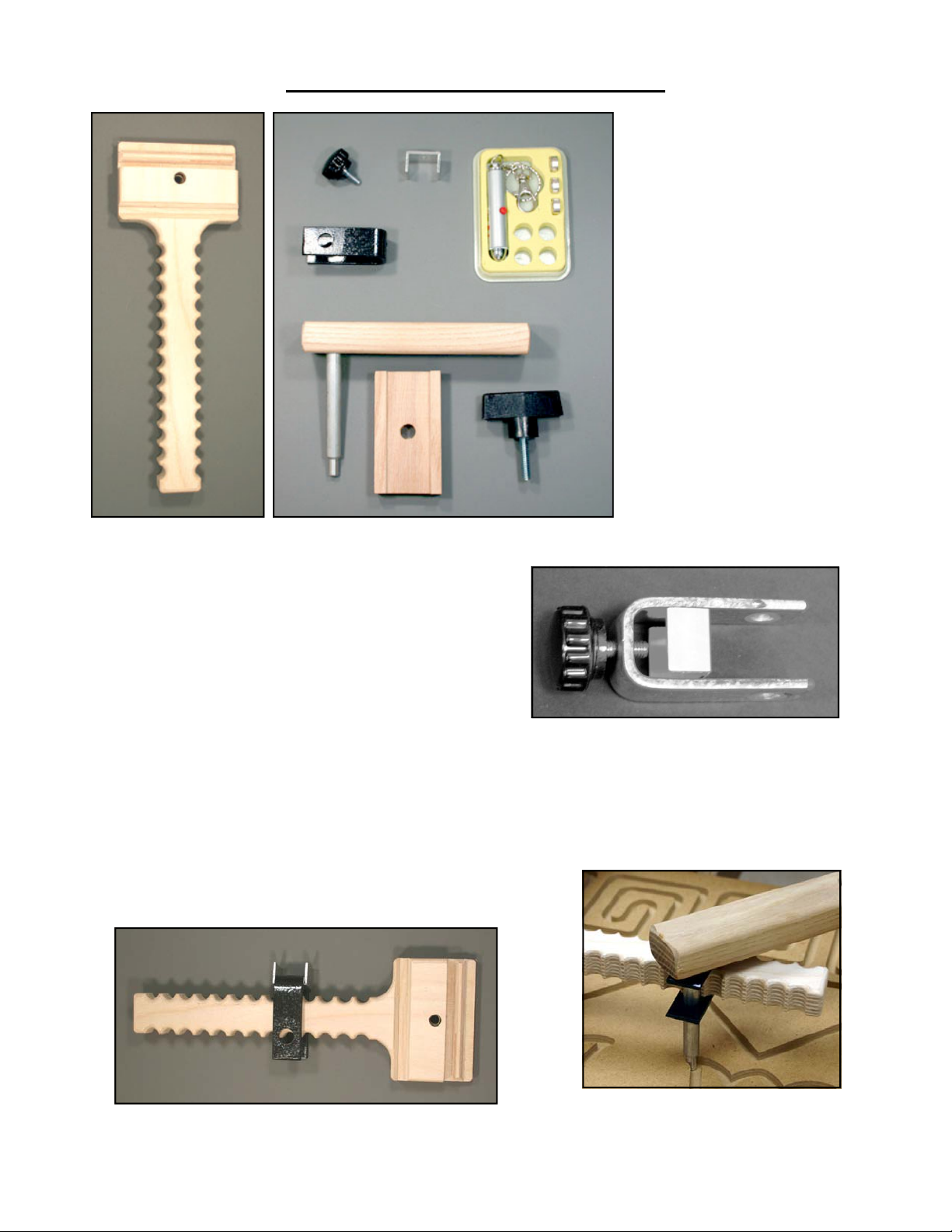
STEP 1.
Begin Handle Assembly
Use machine screws to attach L-shaped
handle part to bottom of upper slide. See
Fig. 1.
The slide has threaded inserts in the bottom.
Insert the first screw part way, carefully en-
gaging the threaded insert. Similarly, insert
the second and third screw part way before
going back and tightening all three.
STEP 2.
Assembling T-Bracket
Slide T-bracket over top of L-shape handle
part. Screw knob with a short stud partway
into T-shaped bracket. The knob should an-
gle towards the back of the slide. Tighten at
desired height. You can re-adjust it later
when you mount the sewing machine on the
carriage. See Fig. 2.
FIG. 1
BACK
FRONT
FIG. 2
T-Bracket
Knob
L-Shaped
Handle
STEP 4.
Attaching U-Handle
Insert knob with long stud through I-
horizontal support, and into U-handle. See
Fig 4. If you have trouble tightening this
knob down all the way, insert the plastic
washer in between the knob and the horizon-
tal support.
A tip for positioning the U-Handle:
Tighten the U-handle knob until it is snug
Hold knob and turn the handle itself in a
tightening direction, while tightening the
knob. After a few tries alternately tightening
the knob and moving the U-handle, you will
end up with the handle in the position you
want and it will be tight.
CARRIAGE HANDLE INSTRUCTIONS
Locate bag of hardware labeled “Carriage Handle Hardware”
STEP 3.
Assembling Metal Handle
Slide I-horizontal handle support bar into the
top of the T-bracket. Tighten in place with
knob with short stud.
The holes drilled thru the bar should be lo-
cated on the sides of the bar.
See Fig. 3.
I-Horizontal
Handle
Holes
FIG. 3
FIG. 4
U-Handle
19
FIG. 3
POINTER PACKAGE INSTRUCTIONS
Parts: Part #
A Wood T-support 1201
B Wood gripper 1200
C Wood stylus holder 1202
D Black Bar Knob 3116
E Small black knob 3077
F Laser Pointer 3078
G Metal stylus fastener 3079
H Metal U-shape 3080
C
D
E
G
H
F
B
A
FIG. 1
STEP 2.
Attach Stylus Holder
Slide the stylus fastener (with the u-shaped
piece inside) onto the T-support (See Fig. 2)
and insert the stylus thru the large holes (See
Fig. 3). Tighten the black knob until the stylus
fastener is holding the stylus securely. The
metal U-shaped piece protects the side of the
wood from the end of the knob.
STEP 1.
Assembling Stylus Fastener
Thread the small black knob into the stylus
fastener.
Place the U-shaped metal piece into the stylus
fastener as shown in Fig 1.
FIG. 2

20
FIG. 8
FIG. 7
FIG. 4
STEP 4.
Attach Laser Pointer
Set the laser pointer in the large hole in the
end of the stylus holder. You may want to
cut off the key ring with a wire cutter. To turn
on the laser pointer, push it down so that the
button is depressed. When you are done us-
ing the laser pointer, raise it back out of the
hole so that it turns off again. See Fig. 7
STEP 5.
Template Stylus
The end of the stylus has been turned down
to fit inside a 1/4” template groove.
Loosen the small black knob and lower the
stylus down into the groove. When not using
the template stylus, you can secure it above
the height of the template board so that it
doesn’t interfere with your laser pointer.
You can order template boards with pre-cut
patterns from our website, or you can create
them yourself with a hand-router.
STEP 3.
Attach Gripper to Carriage
Insert the stud on the large knob through the
gripper and into the threaded hole in the T-
support.
You can screw the knob into the hole a few turns
and then slide it onto the end of the carriage.
See Fig 4
One side of the gripper is larger than the other,
make sure that you have the gripper oriented the
correct way (See Figs 5 & 6). If incorrectly as-
sembled it will tilt slightly up on one side.
FIG. 5
RIGHT FIG. 6
WRONG
Table of contents
Other Hinterberg Design Sewing Machine Accessories manuals


