HIOS BLT-AY-71 User manual

Power Supply for Automatic Brushless Screwdriver
BLT-AY-61 / BLT-AY-71
Instruction Manual
(April 2018)
No.ET-A048 18A

Table of Contents
03 Safety Instructions
04 What Can Be Done with This Unit:
05 Parts and Their Functions
Front
Rear
Conguration of I/O Circuit
Inside the Cover
Switching Between Reading Start and Pulse Start
09 Change the Operational Settings of the Automatic Screwdriver
Basic Setting Procedure
List of Setting Items and Setting Values
12 Relation Between the Rotation Number and Torque of the Automatic Screwdriver
BLF-2000/BLF-5000
BLF-7000/BLF-7000X/BLF-7025X
PGF-3000/PGF-5000/PGF-7000
15 Torque Up Settings
Clutch Mechanism
17 Timing Chart Table
36 Specications
External Dimensions
38 Terminology Related to This Unit
39 China RoHS2 Table

03
Installation
◦Do not install this unit in a place with a lot of dust, dirt,
metal pieces, etc.
◦Use this unit in the operating environment of
temperatures between 5 to 40 °C and humidity of 80%
or less (no dew condensation).
◦Do not place heavy objects on top of this unit or stack
them.
◦Choose a stable location with no vibrations. Especially,
when installing this unit in a high place, x it rmly.
◦Do not install this unit near high-voltage equipment
or in a noisy environment.
Handling
◦On any commercial power supply, be sure to install an
earth leakage breaker and a safety breaker.
◦Connect the earth wire and use this unit with the
specied rated voltage.
◦The load connected to the output terminal on the
back should not exceed the rated load. Exceeding the
rated load may cause a malfunction.
◦If external devices connected to the I/O ports on the
back are aected by the electromagnetic induction
load from the relay, solenoid valve coil or others, take
measures against noises by using a diode to absorb
reverse voltage. Otherwise, it may cause a malfunction
and failure.
◦When the automatic screwdriver is locked or
overloaded, the overload protection works. Please
note that if the overload protection works frequently,
that operation may impose a load larger than the
capability of this unit or the automatic screwdriver.
◦Even if it is properly used, if the overload protection
works frequently with abnormal events including
heat-up, immediately stop using it, turn o the power,
unplug the power cord, and send it to our service
department for repair.
◦When you tighten screws of workpieces such as resin
products that are charged with a lot of static
electricity, discharge them before screw tightening. If
the workpieces are not completely discharged, static
electricity may ow into the unit from the tip of the bit
causing malfunctions.
◦When external equipment is to be used with an
external power supply using the function of this unit,
use the GND as the common terminal.
◦Failure to do so may cause a malfunction and failure.
◦Do not apply a voltage to the input side. It may cause
a malfunction.
◦Do not make the wiring for input / output longer than
necessary.
◦Note that bundling power cables together may cause
a malfunction.
◦Do not connect parts other than specied ones to the
connection part of this unit. It may cause a
malfunction.
◦Do not disassemble or remodel this unit. It may cause
a malfunction.
◦In that case, we may not be able to accept your claim
for warranty or repair.
◦Do not cause any strong impacts or vibrations against
this unit.
◦Do not drag cords and do not allow them to touch oil
or sharp edges, or to be trapped under heavy objects.
◦When connecting/disconnecting the power cord or
screwdriver cord, always hold the plug.
◦If it is not used for a long time, turn o the power and
disconnect the power plug from the outlet for safety.
Illustrations
◦Illustrations used in this manual are those for BLT-
AY-61 unless otherwise specied. However, if models
have dierences, multiple illustrations are also
displayed with the model names such as "BLT-AY-61 /
BLT-AY-71."
Safety Instructions
Please read this instruction manual carefully before use to ensure proper operations.

04
What Can Be Done with This Unit:
◦Rotation speed can be switched between high and low, and each speed has 11 steps.
◦The forward and reverse rotations as well as high speed and low speed rotations of the automatic screwdriver
can be externally controlled.
◦The FOR input for forward rotation can be switched between pulse/reading (for details, see P.08).
◦Tightening check (impact number) can be set, and torque-up trigger in forward or reverse rotation can be
selected.
Note:
Torque-up for reverse rotation is not available for a standard automatic screwdriver because the one-way
clutch works.
◦For tightening reverse screws, a special automatic screwdriver for reserve screws is required.
◦A special automatic screwdriver for reverse screws is available as an option. Please contact our distributor.
◦When using the forward rotation screwdriver for reverse rotation, set the reverse torque-up to U0 or d0 (for
example, when engaging a screw with the bit).
◦The mode of the signal input can be selected in coordination with the movement of the cam movement when
torque-up is set. Also, torque-up for reverse rotation can be set (in the case where the screwdriver for reverse
screw is used).
Example 1: set to U1 (torque-up trigger: once) to tighten a screw at high speed with one impact
Example 2: set to d3 (torque-down trigger: 3 times) to tighten a screw at low speed with three impacts
◦Overtime protection
This is to protect this unit and the automatic screwdriver. Even if the screwdriver happens to keep rotating, it
can stop automatically, and the buzzer noties it when the overtime protection is set on the controller.
◦Overload protection
This is to protect this unit and the automatic screwdriver. If the screwdriver happens to receive overload, it can
stop automatically and the buzzer or the display noties it.
Note:
If the overload protection works frequently, that operation may impose a load that exceeds the capability of this
unit or the automatic screwdriver.
◦The built-in buzzer can be switched o. (For details, see P.08.).
◦The terminal block on the rear panel is detachable, and it is easy to install or replace it.
Note:
◦BLT-AY61 is only for BLF-2000/BLF-5000 and PGF-3000/PGF-5000.
◦BLT-AY71 is only for the BLF-7000 series and PGF-7000.
◦Please do not connect the screwdriver to any power source other than specified one. Otherwise, it may cause a
malfunction or a problem.
05
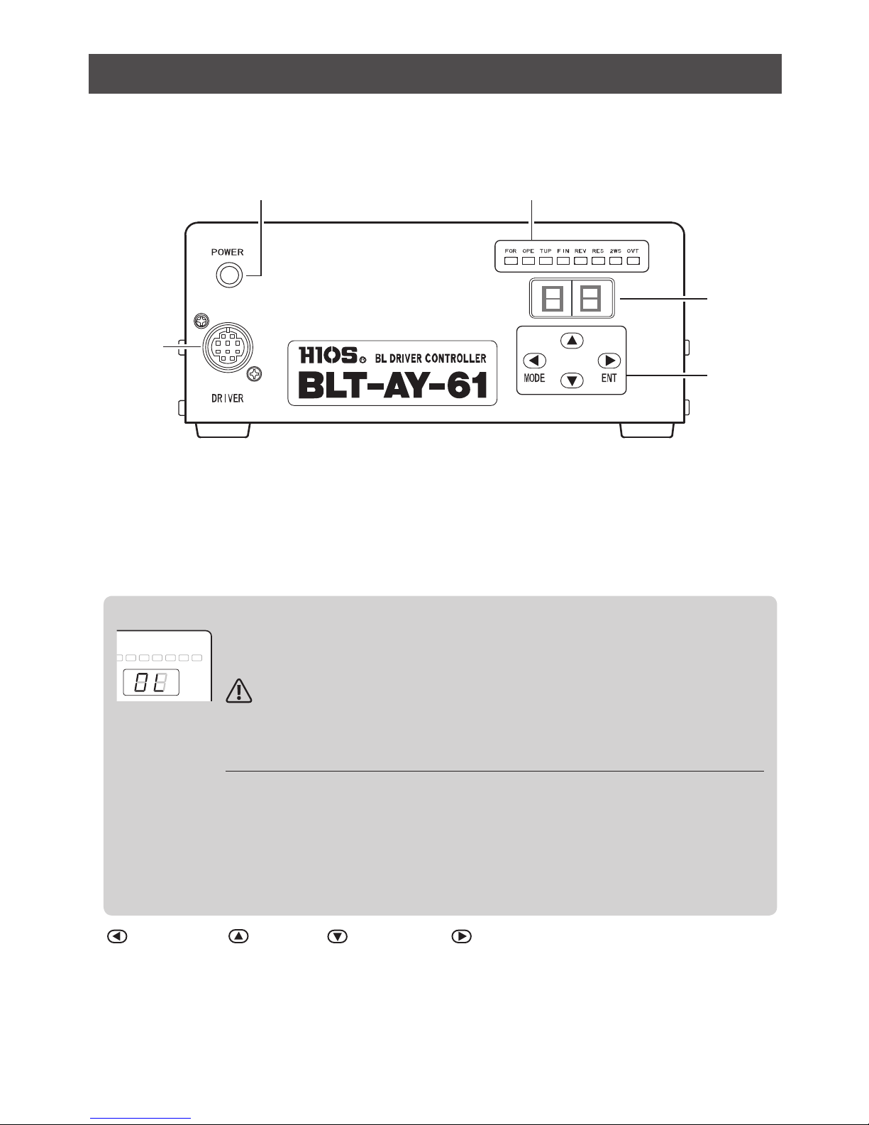
Parts and Their Functions
The functions on the front and rear are displayed commonly on BLT-AY-61 and BLT-AY-71.
■Front
❶
❸
❹
❺
❷
❶Power indicator
Lights up when the machine is power ON.
❷Operation display LED
The external I/O and the operational conditions of the screwdriver can be checked by looking at LEDs’on/o.
❸Setting value display 7-segment
The number of torque-ups and the set rotation speed for the automatic screwdriver are displayed.
POWER
DRIVER
ON
OFF
I
O
FOR OPE
TUP FIN REV RES 2WS OVT
MODE
ENT
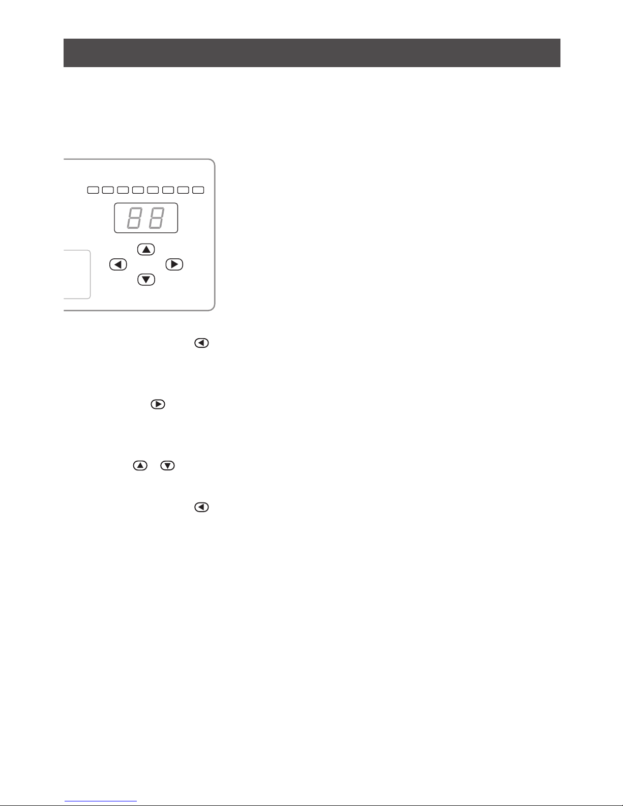
This is displayed when the overload protection works.
To release this, turn off the power of this unit and wait for one minute before turning it on again.
What does OL mean?
Note:
If the overload protection works frequently, that operation may have been imposing a load
that exceeds the capabilities of this unit or the automatic screwdriver.
Cases of overload
・The screwdriver is misaligned to the screw hole
・No device (such as a damper) to alleviate the shock to the screwdriver is attached
・The interval of screw tightening is too short
・In case of screws with hexagonal socket holes or screws with hexalobular socket holes; they
are likely to be obliquely tightened
・
In case of tightening a tapping screw with a long neck on a sticky material such as resin material
❹MODE button/ UP button/ DOWN button/ ENT button
The operational settings and the related values for the automatic screwdriver can be changed. For details, see
P.09.
❺Connector for the brushless screwdriver
The screwdriver cord is connected here.

06
■Rear
REV
2WS
RESET
FOR
NC
NC
NC
NC
FINISH
COM
1 2 3 4 5 6 7 8 9 10
❶❸❷
❶Inlet with a fuse holder
Connect the power cord here.
❷Main SW
This switch turns power on and o. When turning on, the switch lamp is lit and the operation display LED and
the setting value display segment are lit for about 1 second.
❸External I/O terminals/terminal block connector on the main unit side
Connect the terminal block connector here. The forward and reverse rotations as well as high speed and low
speed rotations of the automatic screwdriver can be externally controlled.
No. I/O Signal name Description
1 External output FINISH output The signal is output when screw tightening is completed. It is canceled
when next FOR or REV input comes in or when there is a RESET input.
2 Common COM The signal is common for input and output.
3 External input REV input The signal is input to make the screwdriver rotate reversely. Reverse
rotation continues as long as there is input.
4 External input 2WS input The rotation speed of the automatic screwdriver can be switched
between two steps. The speed is LOW as long as there is input.
5 External input RESET input This is used to stop the automatic screwdriver.
6 External input FOR input
This is used to rotate the screwdriver forward.
The start type can be selected either pulse start or reading start.
The switching from one type to another can be done using the DIP SW
built in the board (SW6-2). (For details, see P.08.)
●Pulse input
The forward rotation starts when a pulse (100mS or larger) is entered as
FOR input.
To stop the rotation, enter a RESET input.
●Reading input
The forward rotation continues as long as there is a FOR input.
To stop the rotation, either turn o FOR input or enter a RESET input.

07
Conguration of I/O Circuit
−
+
No.6: FOR input terminal
The input circuit consists of
the photo coupler input.
Drop the input terminal to
the GND level with an open
collector or the like.
When importing the output, do so within the specied range.
(Maximum DC 24V 500mA. Be careful not to exceed this maximum
value due to a counter-electromotive force especially when connecting
inductive devices such as a relay. Also, for both input and output,
make the wiring to the connected device as short as possible and take
measures against noises.)
Dry contact is used for
the output circuit.
One side is shared with
GND.
No.5: RESET input terminal
Circuit conguration same as above
Circuit conguration same as above
Circuit conguration same as above
No.4: 2WS input terminal
No.3: REV input terminal
No.2: COM input terminal
No.1: FINISH output terminal
Internal circuit
Internal
circuit
Internal power source
+12V
12V 10mA max
Transistor, photo-coupler,
etc.
Example of external circuit
Load
resistor
Load
resistor
GND

08
■Inside the Cover
❶❷
DIP SW
Screws on the side
❶SW of the buzzer
This can sound or mute the buzzer.
・
ON: sound
・
OFF: mute
❷SW for reading/pulse start
This can switch the start mode.
・
ON: pulse start (factory setting)
・
OFF: reading start
Switching Between Reading Start and Pulse Start
1. Turn o the power of this unit and unplug the power cable from the outlet.
2. Remove the screwdriver cord from the connector.
3. Unscrew eight screws on the side and remove the cover of the unit.
4. Change the SW6-NO.2 on the board on the front side inside the unit.
Be careful that nothing is left inside of BLT-AY-61/BLT-AY-71.
5. After completion, attach the cover.
09
Change the Operational Settings of the Automatic Screwdriver
To change the settings of the automatic screwdriver, input RESET and turn o all the operation display LEDs by
cancelling the inputs such as 2WS.
■Basic Setting Procedure
POWER
DRIVER
ON
OFF
I
O
FOR OPE TUP FIN REV RES 2WS OVT
MODE
ENT
1Press and hold the button.
◦The buzzer sounds twice in 2 seconds and the setting mode starts.
◦The operation display LED and the setting display segments are lit.
2Press the to select a target item.
◦The operation display LED and the setting display 7-segment will change.
◦For the setting items, see P.10.
3Press / to change the setting value.
◦For the setting value, see P.10.
4Press and hold the button.
◦The buzzer sounds twice after 2 seconds and the setting mode ends.
◦The operation display LED and the setting display segments turn o.
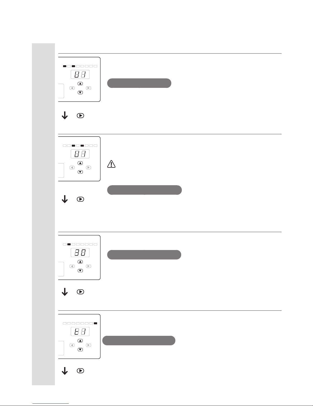
10
Setting of the number of impacts for forward rotation and torque-up trigger
This is to set the number of impacts in forward rotation and the type of torque-up
trigger.
When U0/d0 is set, impacts continued to be applied without torque up.
Setting value (initially U1)
U: Up trigger
d: DOWN trigger
0 to 4: the number of impacts
Setting of the number of impacts for reverse rotation and torque-up trigger
This is to set the number of impacts in reverse rotation and the type of torque-up
trigger.
When U0/d0 is set, impacts continued to be applied without torque up.
Note:
When reverse rotation is used for the screwdriver specied with the forward
rotation, never fail to set this U0 or d0.
Setting value (initial value: U0)
U: UP trigger
d: DOWN trigger
0 to 4: the number of impacts
Setting of rotation speed
This sets the high rotation speed among 11 steps. For details of setting value and
rotation speed, see P.12.
Setting value (initial value: 30)
20 to 30
Overtime setting
If the automatic screwdriver keeps rotating, this stops it automatically to protect this
unit and the screwdriver.
Usually, set this in the program on the system including PLC.
Setting value (initial value: t0)
t0 to t9 (t1: about 10 sec. to t9: about 90 sec., t0: about 42 minutes)
■List of Setting Items and Setting Values
POWER
DRIVER
ON
OFF
I
O
FOR OPE TUP FIN REV RES 2WS OVT
MODE
ENT
POWER
DRIVER
ON
OFF
I
O
FOR OPE TUP FIN REV RES 2WS OVT
MODE
ENT
POWER
DRIVER
ON
OFF
I
O
FOR OPE TUP FIN REV RES 2WS OVT
MODE
ENT
POWER
DRIVER
ON
OFF
I
O
FOR OPE TUP FIN REV RES 2WS OVT
MODE
ENT
Rotation
setting
HIGH
To LOW
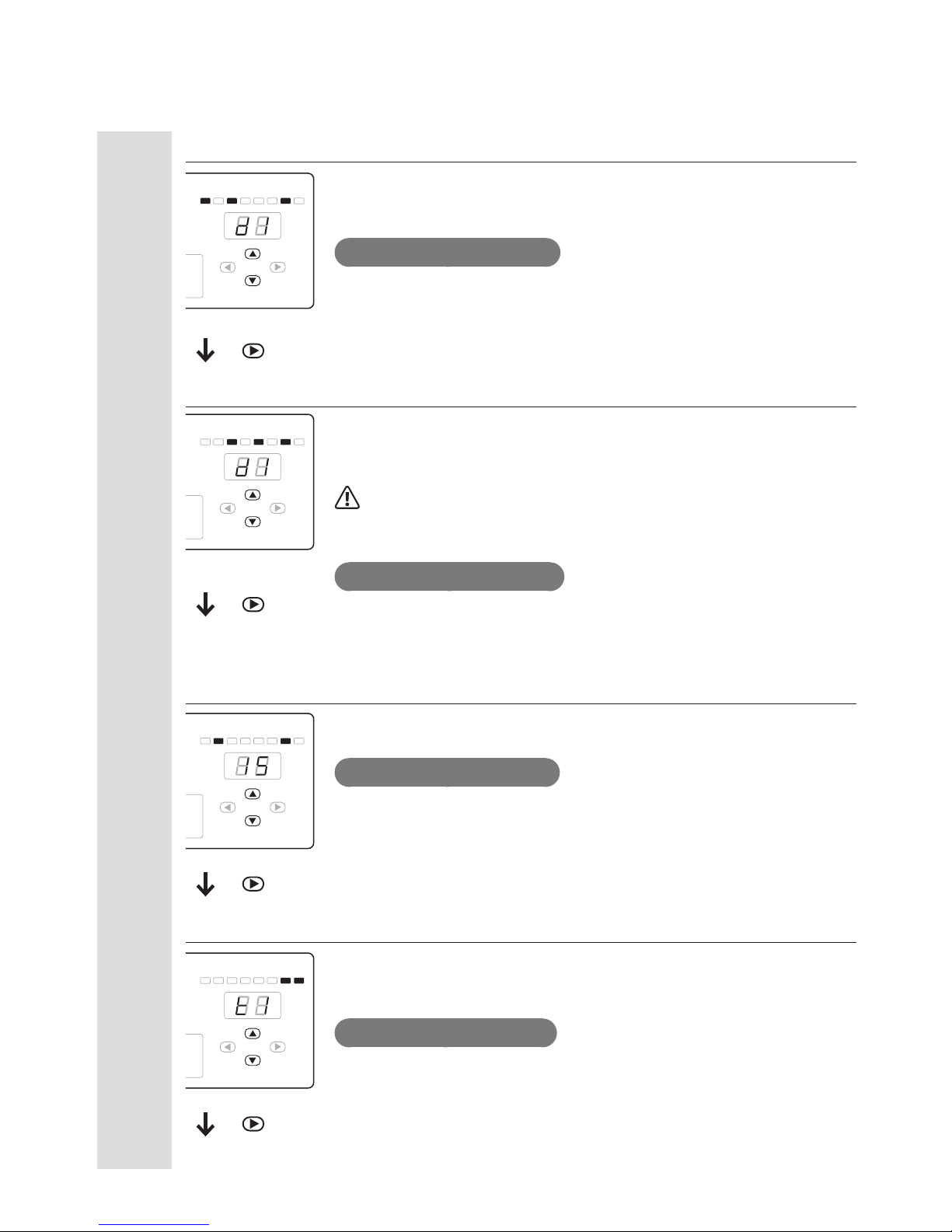
11
Setting of the number of impacts for forward rotation and torque-up trigger
This sets the number of impacts in forward rotation and the type of torque-up
trigger.
When U0/d0 is set, impacts continued to be applied without torque up.
Setting value (initial value: d1)
U: UP trigger
d: DOWN trigger
0 to 4: the number of impacts
Setting of the number of impacts for reverse rotation and torque-up trigger
This is to set the number of impacts in reverse rotation and the type of torque-up
trigger.
When U0/d0 is set, impacts continued to be applied without torque up.
Note:
When reverse rotation is used for the screwdriver specied with the forward rotation,
never fail to set this U0 or d0.
Setting value (initial: value: d0)
U: UP trigger
d: DOWN trigger
0 to 4: the number of impacts
Setting of rotation speed
This sets the low rotation speed among 11 steps. For details of setting values and
rotation speeds, see P.12.
Setting value (initial value: 15)
05 to 15
Setting of overtime
If the automatic screwdriver keeps rotating, this stops it automatically to protect
this unit and the screwdriver.
Usually, set this in the program on the system including PLC.
Setting value (initial value: t0)
t0 to t9 (t1: about 10 sec. to t9: about 90 sec., t0: about 42 minutes)
Rotation
setting
LOW
POWER
DRIVER
ON
OFF
I
O
FOR OPE TUP FIN REV RES 2WS OVT
MODE
ENT
POWER
DRIVER
ON
OFF
I
O
FOR OPE TUP FIN REV RES 2WS OVT
MODE
ENT
POWER
DRIVER
ON
OFF
I
O
FOR OPE TUP FIN REV RES 2WS OVT
MODE
ENT
POWER
DRIVER
ON
OFF
I
O
FOR OPE TUP FIN REV RES 2WS OVT
MODE
ENT
To HIGH

12
Relation Between the Rotation Number and Torque of the Automatic Screwdriver
Note:
These values are only for reference, and they do not guarantee actual performances.
◦Set the number of rotations to ±10% of a specified value.
◦The number of rotations was measured as free run. The number of rotations varies depending on the load over 27.
◦The number of rotations may fluctuate between forward and reverse rotations.
◦The torque was measured by a combination of our torque meter and Fidaptor.
◦The reference table of output torque is listed in the instruction manual of the automatic screwdriver. Refer to them
at the same time.
◦If the overload protection works, change the rotation setting.
■BLF-2000/BLF-5000
Rotation setting
BLF-2000*1BLF-5000
r.p.m Torque (N
・
m) r.p.m Torque (N
・
m)
max. min. max. min.
LOW
05 120
0.35 0.03
115
0.6
0.3
06 150 135
07 165 150
08 187 180
0.8
09 210 195
10 232 210
11 270 240
12 285 255
1
13 300 285
14 315 300
15 345 320
HI
20 690
0.35 0.03
660
1 0.3
21 720 690
22 750 720
23 780 750
24 810 780
25 825 810
26 870 840
27 975 940
28 975 940
29 975 940
30 975 940
*1 For the torque adjustment spring for BLF-2000, two types are available. The silver spring for high torque (accessory), the black
spring for low torque (installed inside of screwdriver). Please select a suitable one for your work.

13
■BLF-7000/BLF-7000X/BLF-7025X
Rotation setting
BLF-7000/BLF-7000X BLF-7025X
r.p.m Torque (N
・
m) r.p.m Torque (N
・
m)
max. min. max. min.
LOW
05 150
1.1
0.7
120
1.4
1.2
06 180 140
07 210 160
08 240 180
09 270 210
10 300
1.5
230
11 330 250
12 360 280
2
13 390 300
14 420 320
15 450 350
HI
20 495
2 0.7
400
2.5 1.2
21 510 420
22 540 440
23 570 470
24 600 490
25 615 510
26 645 540
27 735 600
28 735 600
29 735 600
30 735 600

14
■PGF-3000/PGF-5000/PGF-7000
Rotation setting PGF-3000 PGF-5000 PGF-7000
r.p.m r.p.m r.p.m
LOW
05 115 115 210
06 135 135 250
07 155 155 285
08 175 175 325
09 200 200 365
10 220 215 400
11 240 240 440
12 260 260 480
13 280 280 520
14 300 300 555
15 325 320 595
HI
20 625 690 645
21 655 720 670
22 700 755 710
23 730 785 740
24 765 820 770
25 800 850 800
26 840 890 840
27 950 985 935
28 950 985 935
29 950 985 935
30 950 985 935
15
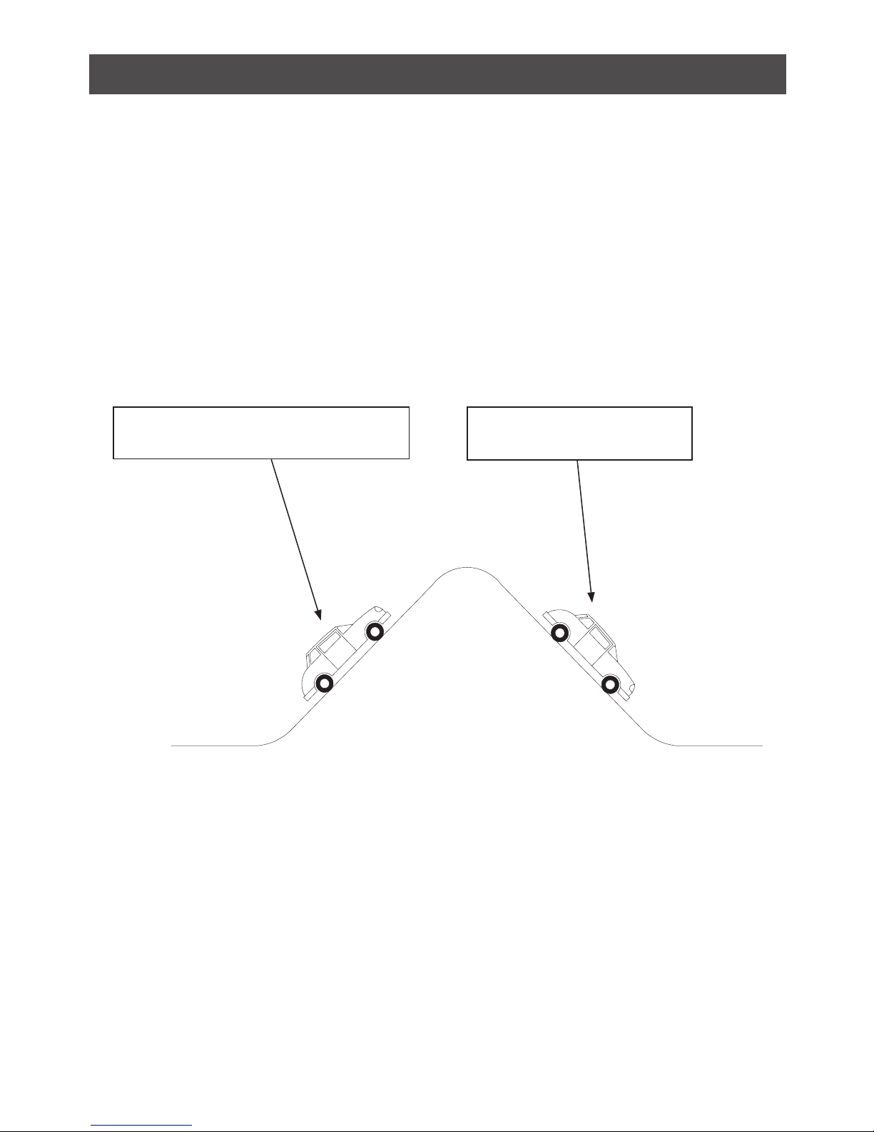
Torque Up Settings
Most customers are undoubtedly experienced in driving a car, and are aware that cars traveling up a slope at a
high speed will end up going over the mountain even when the brakes are applied, while cars traveling at a low
speed will come to a stop before reaching the top of the mountain when the brakes are applied.
The automatic brushless screwdriver BLF-series uses a system that traverses the lobe of a mechanical cam to
apply torque to screws. To ensure that torque is applied to the bit accurately, a clutch is used when traversing the
cam. The timing of the application of the brake when the bit is rotating at high speeds and low speeds is required
to be adjusted to traverse the lobe of the cam.
The BLT-AY-61/BLT-AY-71 controller is designed to control the rotational speed of the driver over a large range of
speeds from low to high, as well as to allow settings for torque up with DOWN trigger at low speeds and UP
trigger at high speeds.
Applying the brakes here at a high speed will result in
the car stopping past the top of the mountain.
The brakes are applied at a low speed
here.

16
■Clutch Mechanism
The clutch mechanism is described below.
Detection SW
"OFF"
Cam
Cam
Cam
Cam
Roller
Roller
Roller
Roller
Torque adjustment
pressure
Movement to
traverse cam
Movement to traverse cam
Movement to
traverse cam
Movement to
traverse cam
Torque adjustment
pressure
Torque adjustment
pressure
Torque adjustment
pressure
Detection SW
"ON"
Detection SW
"ON"
Detection SW
"ON"
1
2
3
4
Diagram of the mechanism that
allows the driver to detect torque.
If the speed when traversing the
cam is high, the detection SW turns
ON (before traversing the cam) and
the brake is applied to the motor.
If the speed when traversing the
cam is low, the detection SW turns
OFF (after traversing the cam) and
the brake is applied to the motor.
By traversing the cam, torque is
transferred accurately and the
screw is completely tightened.

17
Timing Chart Table
Note:
◦If a pulse input is to be used for START and RESET, always use an input of 100 mS or more.
◦Set the interval between one START and the next START to 100 mS or more for the reading START settings.
◦Do not change the external input during torque up operations (impact).
◦Always control the input sequence in a single direction when switching between forward and reverse rotation.
No. Start Type
Impact setting value
2WS setting Bit rotation
FOR/HIGH FOR/LOW REV/HIGH REV/LOW
Timing Chart 01 Pulse Start U1 − − − HIGH FOR
Timing Chart 02 Pulse Start U3 − − − HIGH FOR
Timing Chart 03 Pulse Start − d1 − − LOW FOR
Timing Chart 04 Pulse Start − d3 − − LOW FOR
Timing Chart 05 Pulse Start U1 − − − LOW→HIGH FOR
Timing Chart 06 Pulse Start − d1 − − HIGH→LOW FOR
Timing Chart 07* − − − U1 d1 LOW→HIGH REV
Timing Chart 08* − − − U1 d1 HIGH→LOW REV
Timing Chart 09* Pulse Start U1 − − − HIGH REV→FOR
Timing Chart 10* Pulse Start − − U1 − HIGH FOR→REV
Timing Chart 11* Reading Start U1 − − − HIGH FOR
Timing Chart 12* Reading Start U3 − − − HIGH FOR
Timing Chart 13* Reading Start − d1 − − LOW FOR
Timing Chart 14* Reading Start − d3 − − LOW FOR
Timing Chart 15* Reading Start U1 − − − LOW→HIGH FOR
Timing Chart 16* Reading Start − d1 − − HIGH→LOW FOR
Timing Chart 17* Reading Start U1 − − − HIGH REV→FOR
Timing Chart 18* Reading Start − − U1 − HIGH FOR→REV
* The timing charts are applied to screwdrivers for counter-clock-wise for automatic BLF brushless screwdriver. Please note that they
are not applied to standard types.

18
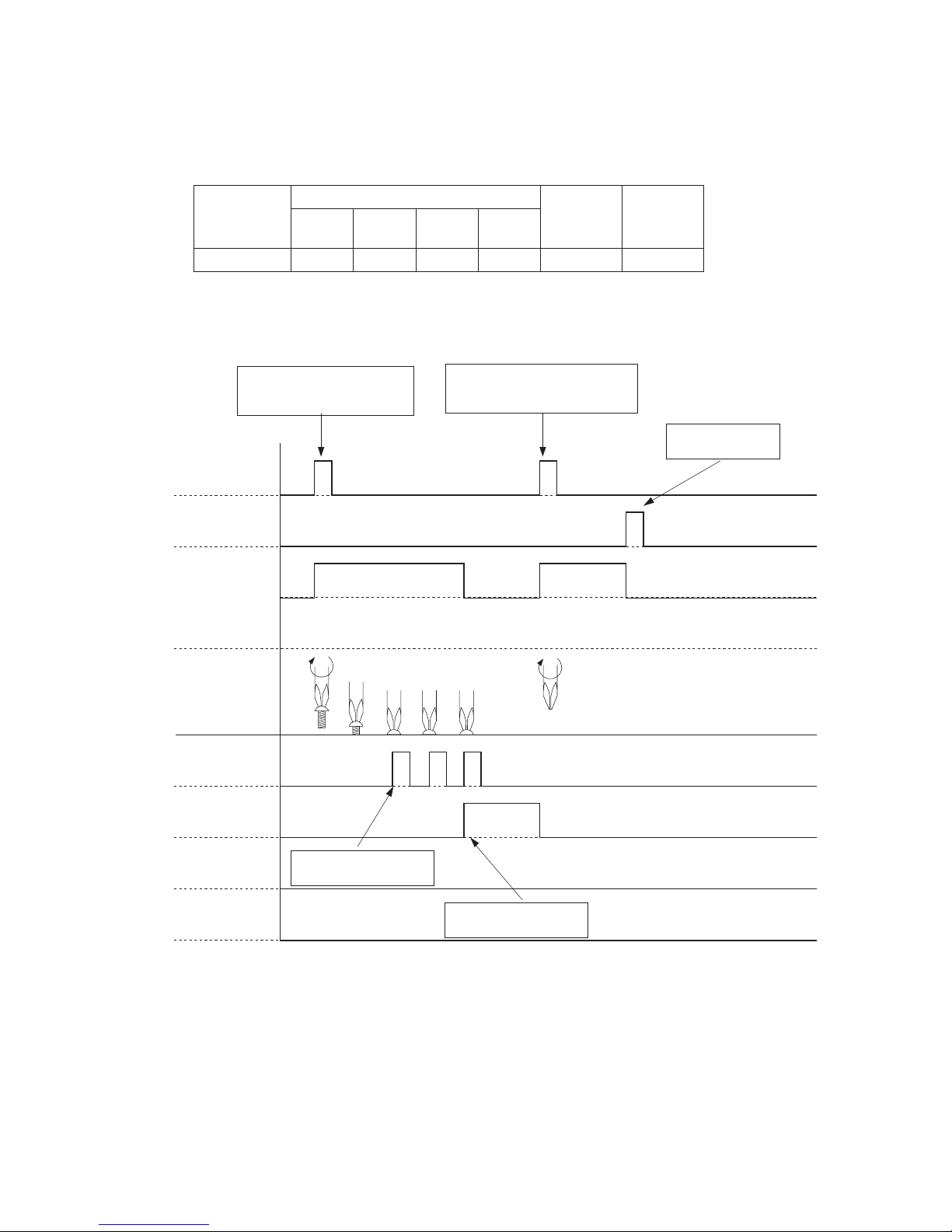
■Timing Chart 01
Start Type
Impact setting value
2WS setting Bit rotation
FOR/
HIGH
FOR/
LOW
REV/
HIGH
REV/
LOW
Pulse start U1 ー ー ー HIGH only FOR only
Use “Pulse input” for the
FOR input to rotate the
driver
When the screw has been seated
and torque up operation has started
Freely rotate the bit to
mesh with the screw
At the next START when
FINISH output is OFF
At RESET when
FINISH output is OFF
Use “Pulse input” for the
RESET input to stop the
rotation of the driver
*Use “Pulse input” of 100 mS or more
FOR input
RESET input
Screw condition
Torque up
FINISH output
2WS input
REV input
FOR
Bit rotation
REV
19
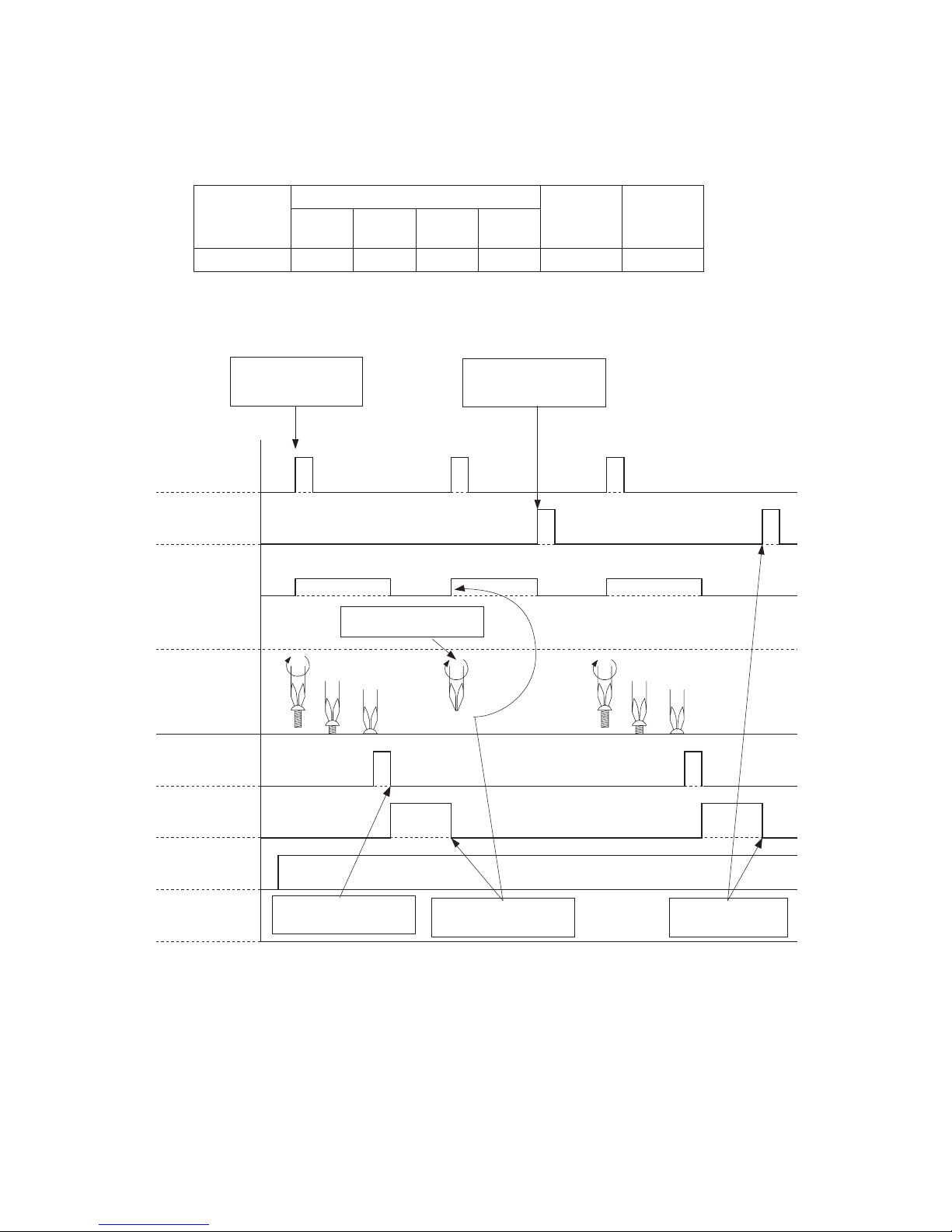
■Timing Chart 02
Start Type
Impact setting value
2WS setting Bit rotation
FOR/
HIGH
FOR/
LOW
REV/
HIGH
REV/
LOW
Pulse start U3 ー ー ー HIGH only FOR only
Use “Pulse input” for the FOR input
to rotate the driver
Rotate stops with
RESET
Impact starts when the
screw has been seated
On the 3rd impact when
FINISH output is ON
Pulse is input for the FOR input and
the driver is rotated freely (if used for
meshing the screw)
*Use “Pulse input” of 100 mS or more
FOR input
RESET input
Screw condition
Torque up
FINISH output
2WS input
REV input
FOR
Bit rotation
REV
20
■Timing Chart 03
Start Type
Impact setting value
2WS setting Bit rotation
FOR/
HIGH
FOR/
LOW
REV/
HIGH
REV/
LOW
Pulse start ー d1 ー ー LOW only FOR only
Use “Pulse input” for the
FOR input to rotate the
driver
When the cam is overcome
and torque up operation
has started
Freely rotate the bit to
mesh with the screw
At the next START when
FINISH output is OFF
At RESET when
FINISH output is OFF
Use “Pulse input” for the
RESET input to stop the
rotation of the driver
*Use “Pulse input” of 100 mS or more
FOR input
RESET input
Screw condition
Torque up
FINISH output
2WS input
REV input
FOR
Bit rotation
REV
This manual suits for next models
1
Table of contents
Other HIOS Power Supply manuals


Popular Power Supply manuals by other brands


Delta Elektronika
Delta Elektronika ES 150 Series product manual

Gossen MetraWatt
Gossen MetraWatt KONSTANTER SPL Series Supplement to operating instructions

Rosewill
Rosewill Valens 500 user manual

Ubiquiti
Ubiquiti UniFi SmartPower USP-RPS quick start guide

Akyga
Akyga AK-ND-15 user manual

Matsusada Precision
Matsusada Precision EJC Series instruction manual