HIOTH TECHNOLOGY CO., LTD CT-SMZW2004-ES User manual

HIOTH User Manual
HIOTH TECHNOLOGY CO.,LTD.
PIR MOTION DETECTOR
Introduction
The Motion Detector is a Z-Wave enabled device which is fully compatible with any Z-Wave
enabled network. Z-Wave enabled devices displaying the Z-Wave logo can also be used with it
regardless of the manufacture, and ours can also be used in other manufacturer’s networks, This
Motion Detector can control our modules via controller settings. Inclusion of this Motion Detector
on other manufacture’s Wireless Controller menu allows remote turn on of connected modules w-
hen the detector is triggered.
The Motion Detector is designed with two detecting sensors, Passive Infra Red (PIR) sensor
and light sensor, in order to fulfill the purpose of security and home automation. Once night falls,
the percentage of ambient illumination is lower than preset value. If a person moves within or
across the device field of vision, a trigger radio signal will be transmitted so as to turn on the con-
nected lightings for better illumination.
CT-SMZW2004-ES
PIR Motion Detector

HIOTH User Manual
HIOTH TECHNOLOGY CO.,LTD.
Technical Information
Compatible with any Z-Wave network controller
Battery powered and cost savings
Support the scene control
Specifications
Radio protocol: Z-Wave 868.42MHz EU
Power supply: DC 4.5V(1.5V AA*3)
RF range:25m (in an open area of the wireless controller and the latest line-of-sight between
Z-Wave receiving module)
Operation Frequency: 908.42 MHz (SP814-2) / 921.42 MHz (SP814-9)
PIR Detection Coverage: Wall-Mounted:
Up to 10m x 110 °(at 1.8m mounting height& 25 °C)
Ceiling-Mounted:
Up to5m x 360 °(at2.8m mounting height& 25 °C)
Dimension:85 mm x 85 mm x 45 mm
Operation
NOTE:
①Lens Cover
②Photocell Sensor
③PIR Sensor
④Two-Color Indication LED(red & green)

HIOTH User Manual
HIOTH TECHNOLOGY CO.,LTD.
⑤Link Key
Fig.1
Z-WAVE NETWORK INCLUSION
In the rear casing, there is a link key which is used to carry out inclusion, exclusion, association
or reset. When the detector is first powered up, the LED flashes on and off alternately and repeate
dly at 2-second intervals. It implies that it has not been assigned a node ID and cannot work with
Z-Wave enabled devices.
1) Connect the power supply, and make sure that device in a state of "No node ID" (2-second
on, 2-second off).
2) Choose "Z-Wave" to enter the Network Inclusion mode on the APP, then click " ".
3) Pressing link key 3 times within 1.5 second (Detector beeps when link key is pressed.).
4) When prompt a message “Request Access Success”, please go to the device list interface, and
refresh the device list, the device will be displayed.
Z-WAVE NETWORK EXCLUSION
1) Make sure the device is connected to the power supply.
2) Remove the device on the APP, then click "finish".
3) Pressing link key 3 times within 1.5 second (Detector beeps when link key is pressed.).
4) Please go to the device list interface, and refresh the device list, the device will not be
displayed.

HIOTH User Manual
HIOTH TECHNOLOGY CO.,LTD.
5) If the device can still be displayed (network exclusion failed), repeat steps 2-4.
NOTE:
If the device is online, directly perform steps 1-5, if the device is offline, need
interruption of the device power supply first, and then perform step 1-5.
MOTION DETECTOR RESET
Reset procedure clears the modules’ EPROM memory, including all information
about the Z-Wave network controller, calibration and power consumption data.
1) Make sure the device is connected to the power supply.
2) Pressing link key 3 times within 1.5 second (Detector beeps when link key is pressed.).
3) Within 1 second, press and hold the link key until beep stops (A long beep is sounded for 5
seconds).
4) IDs are excluded and all of preset value will be reset to factory default (2-second on, 2-second
off).
Installation Instructions
It’s recommended to install the Motion Detector on a wall or under a ceiling.
MOTION DETECTOR INSTALLATION
1) Undo and remove the screw from the bottom edge of the detector to detach the rear cover
(Fig.2).
Fig.2
2) Unscrew the screw from the battery cover and remove the battery cover.
HIOTH User Manual
HIOTH TECHNOLOGY CO.,LTD.
3) Insert 3 AA-size 1.5V alkaline batteries to the battery compartment, ensuring correct polarity
is put (Fig.3).
Fig.3
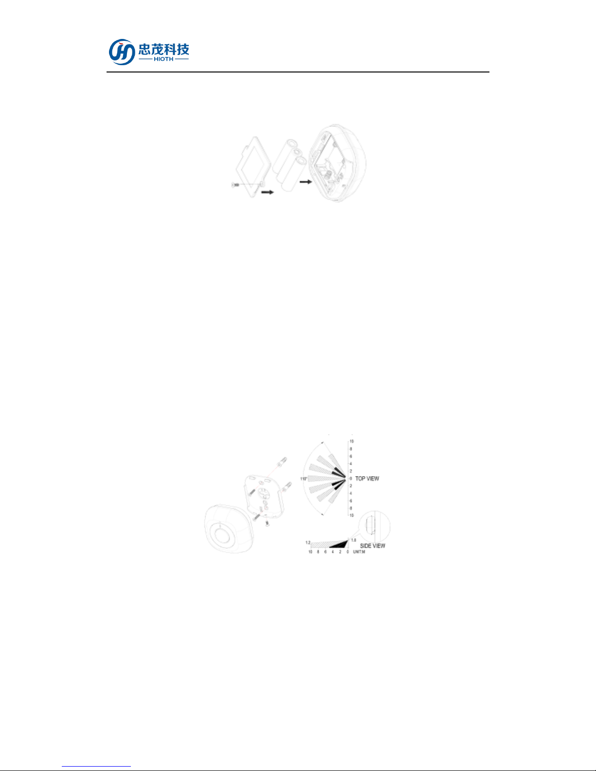
4) Two ways of mounting are applicable to the detector. Decide the detector is to be
wall-mounted (Fig.4) or ceiling-mounted (Fig.5). Hold the rear cover in position and mark
the two mounting holes. Drill the holes, insert the plastic wall plugs and screw the rear cover
to the wall or ceiling using the screws provided.
5) Engage the detector to rear cover firmly.
i. Wall Mounting
The recommended position for wall mounting is at the height of 1.8m from the flood. At
this height, the optimum detection range is up to 10m with coverage range of 110
degrees.
Fig.4
ii. Ceiling mounting
The recommended position for wall ceiling mounting is at the height of 2.8m from the
flood. At this height, the optimum detection range is up to 5m with coverage range of 360
degrees.

HIOTH User Manual
HIOTH TECHNOLOGY CO.,LTD.
Fig.5
Settings (Coverage Range Adjustments)
Two types of lens covers are provided for the detector. Wall-lens cover (Fig.6a) is to be used
when the detector is wall-mounted, whereas ceiling- lens cover (Fig.6b) is to be used when the
detector is ceiling-mounted. The coverage range adjustment is only applicable to ceiling- lens
cove; choose correct lens cover before mounting.
Fig.6a
Fig.6b
NOTICE:
1) The shading cap is composed of 12 segments for limiting the detection coverage, and each
segment covers detection angle of 30 degrees (Fig.6c). Follow the grooves on the cap, cut the

HIOTH User Manual
HIOTH TECHNOLOGY CO.,LTD.
cap to a suitable size and place it onto the ceiling-lens cover (Fig.6d). The remaining
segments are used for blanking off an undesirable detection area.
Fig.6c Fig.6d
2) Simply turn the cover anticlockwise to remove the wall-lens cover from the detector. Once
the wall-lens cover is removed, reload the detector with ceiling-lens cover and turn it
clockwise, ensure the mark on the cover is pointing towards and aligned with the mark on the
detector.
3) To detect movements with detection coverage up to 360 degrees, simply reload the
ceiling-lens cover without shading cap. No movements can be detected if the detector is
reloaded with a shading cap which maintains 12 lens segments.
Safety Notice
Don't make the device directly to the window/fan/air-conditioner or sunlight.
Do not install the device above or facing any source of heat directly, such as fires, radiators,
boilers, etc.
Confirm the device is positioned in place where the light source detected by the detector is
consistent with actual ambient illumination. Do not locate the detector in shadowy place.
Where possible, mount the detector so that the logical path of an intruder would cut across
the fan pattern rather than directly towards the detector.
In order to obtain the best results, please put the detector directly facing the entrance.
Table of contents
Other HIOTH TECHNOLOGY CO., LTD Security Sensor manuals

Popular Security Sensor manuals by other brands


Tollco
Tollco WaterFuse PlugIn VFB700-DN15 User's manual & installation instructions

RKI Instruments
RKI Instruments 35-3010RK-01 manual

Agilent Technologies
Agilent Technologies G3388A Operation manual

Popp
Popp SIRIS operating manual

Rielta
Rielta GRAN-RK installation guide

SICK
SICK deTem2 Core operating instructions

Eldat
Eldat Easywave RCP09 Series quick start guide

PCB Piezotronics
PCB Piezotronics 8120F-410A Installation and operating manual

YOKOGAWA
YOKOGAWA TB820D user manual

AQUALEAK
AQUALEAK WG2 Installation and operation instruction manual

Bosch
Bosch 440 Series installation guide

Guardian
Guardian Halo Big Block SRL instruction manual