HIRAYAMA Hiclave HVE-50 User manual

No PO1G-OO4-A
27-JUL-2001
.
This manual was created to support smooth service of the HVE-50
autoclave. Use the manual as a reference in addition to the operation manual.
No part of this document may be reproduced without permission.
The contents of this document are subject to change without notice.
This document has been cc3refullycompiled. If you have any questions or require
information not covered in 'the manual, please contact:
Amerex Instruments, Inc.
P.O. Box 787
Lafayette, CA 94549 .U.S,A.
TEL: 925-299-0743
FAX: 925-29~1-0745
E-mail: [email protected]
~~foreUsing ',-
.In this manual the following headwords are applied to items to ...yhichgreat attention should be
given: .~
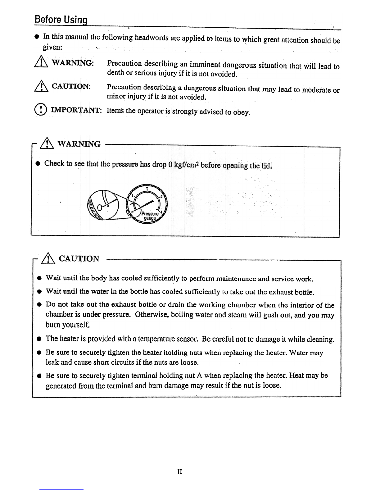
Precautiondescribing an imminent dangeroussituation that will Jeadto
deathorseriousinjury if it is notavoided.
Precaution describing a dangerous situation that may lead to moderate or
minor injury if it is not avoided.
.Wait until the bodyhascooledsufficiently to perfonn maintenanceandservicework.
.Wait until the water in the bottle hascooled sufficiently to take out the exhaustbottle.
.Do not take out the exhaust bottle or drain the working chamber when the interior of the
chamber is under pressure. Otherwise, boiling water and steam will gush out, and you may
bumyourself.
.The heaterisprovided with atemperaturesensor.Be carefulnotto damageit while cleaning..
.Be sure to securely tighten the heaterholding nuts when replacing the heater. Water may
leakandcauseshortcircuits if the.nutsareloose.
.Be sureto securelytightentenninal holding nutA whenreplacingthe heater.Heatmaybe
generatedfrom theterminalandbumdamagemayresultif the nutis loose.
II

Howto ReadThis Manual
.This manual consists of the following sections covering the information required for proper
operation of the autoclave HVE-25/50:
This section describes the maintenance procedures for the unit as we:ll as the methods for
replacing and adjusting the main parts.
Chapter2. Troubleshooting Chart
This sectiondescribestheitemsto checkandmeasur~sto takewhena problemoccurs.
Chapter3. Product Description
This section describesthe operations and internal structural parts of the product.
Chapter4. OperationCheckProcedure
This sectiondescribesthemethodfor checkingtheoperationof electricalpartsusingthecheck
program.
Chapter5. MainPartsList
The code numbers of the main parts arelisted in the table here.
III

.Contents
II
1/1
IV
Introduction """""""""""""""""""!"!"""""'"TableofContentsBefore Using ~How to Read Th1s ManualContents , ,.
1
1
2
3,3
4
5
5
6
7.
8
Chapter 1. Maintenance and Adjustment1. Draining Water from the Exhaust Bottle2. Draining the Working Chamber3. Cleaning the Working Chamber :4. Body Repairs ; , ~ ;;;5. Lid Gasket6. Solid State Relay (SSR) Replacement ~ ; : ; ;7. Replacement of Temperature Sensor for Control8. ROM Replacement , :...,9. Heater Replacement10. Display Board Replacement ! , ,
11
11
13
15
Chapter 2. Troubleshooting Chart1. Error Detection (Alarms) ~ ",.., ;;.;;.., ,...;;.~.~..;:..~2. Early Troubleshooting3. Troubleshooting ::~ ,' ;,
17
17
1'8
20
22
23
27
27
28
28
29
30
31
Chapter 3. Product Description.Operation sequence/proce(jure flow chart , ~.., ..,
.Timing Charts '
.Error Monitoring Charts ; ,.External Appearance.Assembly Diagram.Detailed Display and Operation Switch Diagram.Diagram of Over-pressurization Prevention Switch Area :.Atmospheric Pressure Switch Diagram.Switchboard Diagram.Piping Diagram.Wiring Diagram.Connector Table ;
32
32
32
32
35
Chapter4. OperationCheckProcedure1. CheckProgramOutline2. CheckProgramStartup ,..
3. CheckPrograms ~.Referent~eTableforTemperatureSensorUsedforControl
37
Chapter5. MainPartsList...
IV

Chapter1. Maintenanceand Adjustment
& WARNING ---
.Wait until the body hascooled sufficiently to perform maintenance and servic~ work.
.Turn off the eal1h-leakage circuit breakerbefore replacing any parts.
1. Draining Water from the Exhaust Bottle
.Since the water level in the exhaust bottle increases with continued operation, water must be
drained using the procedure below when water reachesthe HIGH level.
.Wait until the water in the bottle hascooled sufficiently to take out the exhaustbottle.
G) Remove the exhaustbottle from the body.
.Pull the bottle out until the handle canbe grasped then hold and
remove.
@ Place the drain/supply port face down in a level sink.
.Excess water will drain out until the LOW level is reached.
@ Cnfinn thatthewateris atthe LOW level
.Since stearncools in the exhaustbottle, be sureto leave the water
atthe LOW level.
@ Replace the exhaustbottle in the housing area.
.If the bottle is not pushed completely into the housing, an error
( ) will occur when operation starts.

2. Draining the Working Chamber
.Drain water using the following procedure after confirming that the inside of the working
chamberhascooledsufficiently.
.Do not unload the exhaust bottle or drain the working chamber wh~~ t.h~chaIn:~r is under
pressure. Boiling water or steammay gust out causing burns. ;, "
<D Openthelid.
@ Connect one end of the accessory
drainhoseto the tapof thedrainvalve
located at the lower part of the right
sideof thebody.
@ Put the other end of the hose in a
container.
(4) Remove the exhaust bottle from the
body.
@ Turn the drain valve knob, located at
the bottom of the exhaust bottle
housing area, counterclockw~se to
open.
@ Check that draining of the working
chamberis complete.
(Z) Turn the knob clockwise to closethe
drainvalve.
Be surethe exhaustvalve is closed.
2
Cleaning the Working Chamber
3.
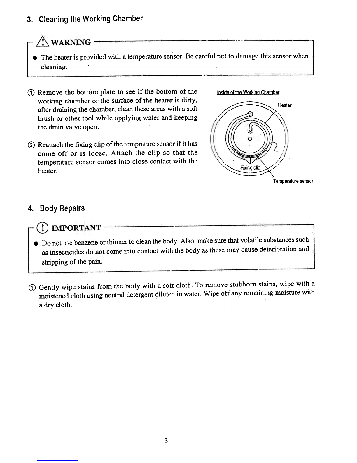
.The heateris provide,dwith atemperaturesensor.Becareful notto damagethis sensorwhen
cleaning.
CDRemove the bott<1>mplate to see if the bottom of the
working chamber or the surface of the heater is dirty.
after draining the chamber, clean theseareaswith a soft
brush or other tool while applying water and keeping
the drain valve open. .
InsideoftheWorkinaChamber
Y=~ Heater
// .~
\
//
\'
@ Reattachthefixing clip of thetempraturesensorif it has
come off or is loose. Attach the clip so that the
temperaturesensorcomesinto closecontactwith the
heater.
//
~, ":.,:_~AI:A, d
~..~::~~~~:::~ '
Tempemluresensor
Body Repairs
4.
.Do notusebenzeneor thinner to cleanthebody. Also, make sure that.volatile substancessuch
asinsecticides do not come into contact with the body asthese may cause deterioration and
stripping of the pain.
CD Gently wipe stains from the body with a soft cloth. To remove stubborn stains, wipe with a
moistened cloth using neutral detergentdiluted in water. Wipe off any remaining moisture with
a dry cloth.
3

5. Lid Gasket
.When the end of the lid gasket becomesdiscolored and whitened, replace the gasket in
accordancewith the following procedure.A worn gasketmaycausesteamleakage.
CDOpenthelid.
@ Lift outandremovetheold gasketinsulation.
@ Using awastecloth, wipe dirt off theareaof the
working chamberwherethe gasketwas..
(1) Remove the gasket band from the old gasket,
andwipe dirt off thebandusingawastecloth.
@ Attachthe gasketbandto a newgasket
.Lay the new gasketonthe chamberandpress
thegasketbandinto thegroove. , 1--- Gasketband
Workingchambercross-section
@ Attachthe newgaskectto theworking chamber.
.Attach while making sure the gasketband
remainsproperlypositioned.
If the gasketband comesout of the groove,
press in the band using a flat-blade
screwdriveror similar tool.
0 Pushthe new gasket down with the fingers to
eliminate anyunevenness.
.,&,$
~~~~~~~~~-- Lidgasket
:.1.$
,.
1~...1!: :1,
, 'I
, '..',
I~ '--.Workingdlamber
.Unevenness in the gasketcancauseleaks.
@ Start normal operationsand confirm thatthere
areno leaksfrom thelid gasket.
Ii

6.
Solid State Relay(SSR) Replacement
CD Pullout the connector from the solid state relay (SSR).
C?)Turn the SSR holding screws and remove the SSR
form the switchboard.
@ Wipe off the heat dissipating grease, dust, and other
matter adhering to the switchboard in the vicinity of
the SSR attachment screw hole.
@ Clean the attachment surface of the new SSR, then
evenly apply heatdissipating greasetQthe surface.
@ Attach the SSR to the switchboard and plug in the
connector.
.Since the IN side of the SSR has +/- polarity, be
sure to attach this side in the original connection
direction.
7. Replacement of Temperature Sensor for Control
<D Hold the sensorand loosen.
@ Pull the temperature sensorfor control from the sensorhr;lding hole.
@ Insert the new sensorthrough the sensorholding ho]e, adjust so the internal working chamber
surface and the end of the temperature sensorare at the sameposition, and firmly tighten the
sensorholder using the fingers and riot a monkey wrench or other tool.
Sensorholder
/
Internalworkingchambersurface
~
"'"
"'--
Temperaturesensorfor control
End ofthe temperaturesensorforcontrol
5
8. ROMReplacement
CD IMPORTANT -
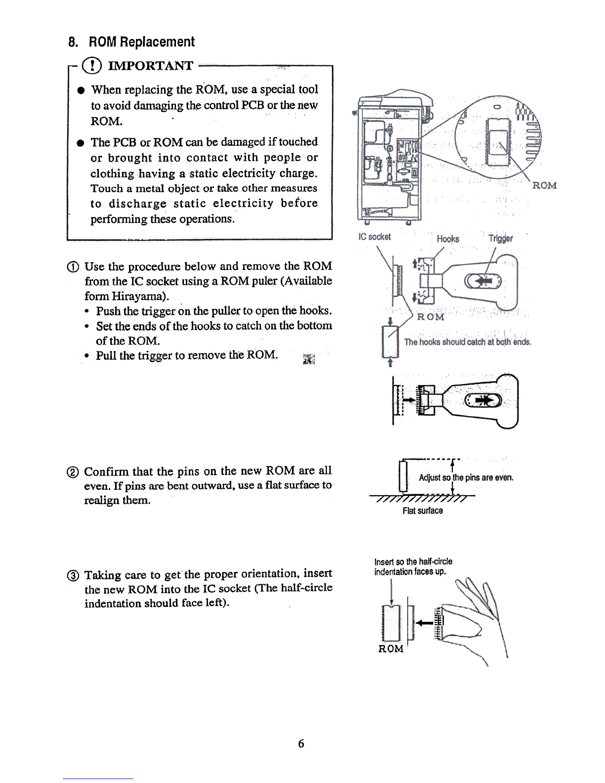
.When replacing the ROM, usea specialtool
to avoid damagingthecontrolPCBorthenew
ROM. .
.The PCB or ROM canbedamagedif touched
or brought into contact with people or
clothing having a static electricity charge.
Touch a metal object or take othermeasures
to discharge static electricity before
performingtheseoperations.
CDUse the procedure below and removethe ROM
from theIC s~cketusinga ROM puler(Available
fomI Hirayama).
.Push thetrigger onthepullerto openthehooks.
.Set theendsof thehooksto catchonthebottom
of theROM.
.Pull the trigger to removetheROM. :if~
@ Confirm that the pins on the new ROM are all
even.If pinsarebentoutward.usea flatsurfaceto
realignthem.
f-
Adjustsothepinsareeven.
~ t-
//////////////
Flatsurface
Insert $0 lIJehalf-circle
indentationfacesup.
@ Taking careto get the proper orientation, insert
the new ROM into the IC socket (The half-circle
indentation should face left).
-+-~I
ROM
6

9.
Heater Replacement
& CAUTION
.Be sureto securely tighten the heaterholding nuts whenreplacing the heater. Water may leak
andcauseshortcircuits if thenutsareloose.
Be sure to securely tighten terminal holding nut A when replacing the heater. Heat may be
generated from the terminal and bum damage may result if the nut is loose.
.Required tools
.Monkey wrench (with maximum opening
width of 23 mm or more)
.Spanners, etc. .
(for 7 mmnut)
G) Drain the water from the working chamber.
@ Turn off the earth-leakage circuit breaker
located on the right side of the body.
@ Remove the plate from the rear of the body.
@ Pull the temperature sensor out from the sensor
fixing tube on the heater.
@ Loosen terminal holding nut A and remove the
round terminal.
Healer"
@ Remove the neaterholding nuts.
.If the nut cannot be removed using a monkey
wrench, lay the body down, and insert a box
spanner into the hole on the underside to
removethenut.
Gasket Workingchamber
FI
Rou Fixingclip
Terminalholdingnut8
-Terminal holdingnutA
<V Remove the heaterfrom the working chamber.
@ Remove anybilge or other matter from the area
around the heaterattachment holes.
@ Remove the heaterholding nuts and flat washers
attachedto the new heater. ..~'.'."""".".""""'.""""'-. \, ., ,
.I ..
, , .,
"., .. \"":0-' .:.;,
:':':"
"1¥::::~~~""::: Heater
, , .
..,. .
;:' t:i
.,' iJ Gasket
,"7 Heaterattachmentholes
~ ..-
~
@ Bring the heater screw sections through the
attachment holes on the bottom of the working
chamber. Be careful that the gaskets do not
come out and fall into the chamber during this
operation.
-M
::~::~~
1:1:::tJ ~ Flatwashers
"""""""~ Heaterholdingnuts
@ Attach the flat washers, then tighten the heater
holding nuts.
@ Remove teffilinal holding nut A from the newly
attachedheater.
7

@ Attach the round terminaland tighten terminal holding nutA. At thi~ point, securet~~inal
holding nutB with a wrenchand stronglytightennutA.
@ I~s~rtthetemperaturesensQrintothefixing tubes. ..,
@ Placewaterin theworking chamberandcheckfor leaksfrom the heaterattnchment(areas. :,.
@ Turn onthee~h-leakage circuit breaker,andbeginoperationin accord;1ucewith theordinary
operationprocedure. Checkto seethutth~reisno.1~akagefrom~e he~~er.inst~.lation@(~awhile
pressureis increasing. Install theplate ontherearof thebody.
10. Display Board Replacement
.Required tools
.Plus driver (for M5 screws)
.Plus driver (for M3 screws)
.Adhesive tape
<D Disconnect connector CNI on the control PCB. Wrap th~ connectof and bracket cable in
adhesive '.tapeto make them pass through the duct easily. ., .-' .' .' ':. ". !
,
Adhesivetape
Connector
@ Openthelid andremovethe holdingscrewsfor the.lidbottom cover..
@ Removethelid coverholding screws.
8

@ Removethe2 tapin screwsonthebackandremovethedisplay.board.
CDLoosenthe2 tapin screwsonthe frontby 1 or2turns.
@ Pressthedisplayto thefrontandbringthenewdisplayboardinto contactwith theholdingrods.
PassthetapinscrewSthroughtheboardholdingseatsanddisplayboardholdingholesandattach
to thelid cover.
9
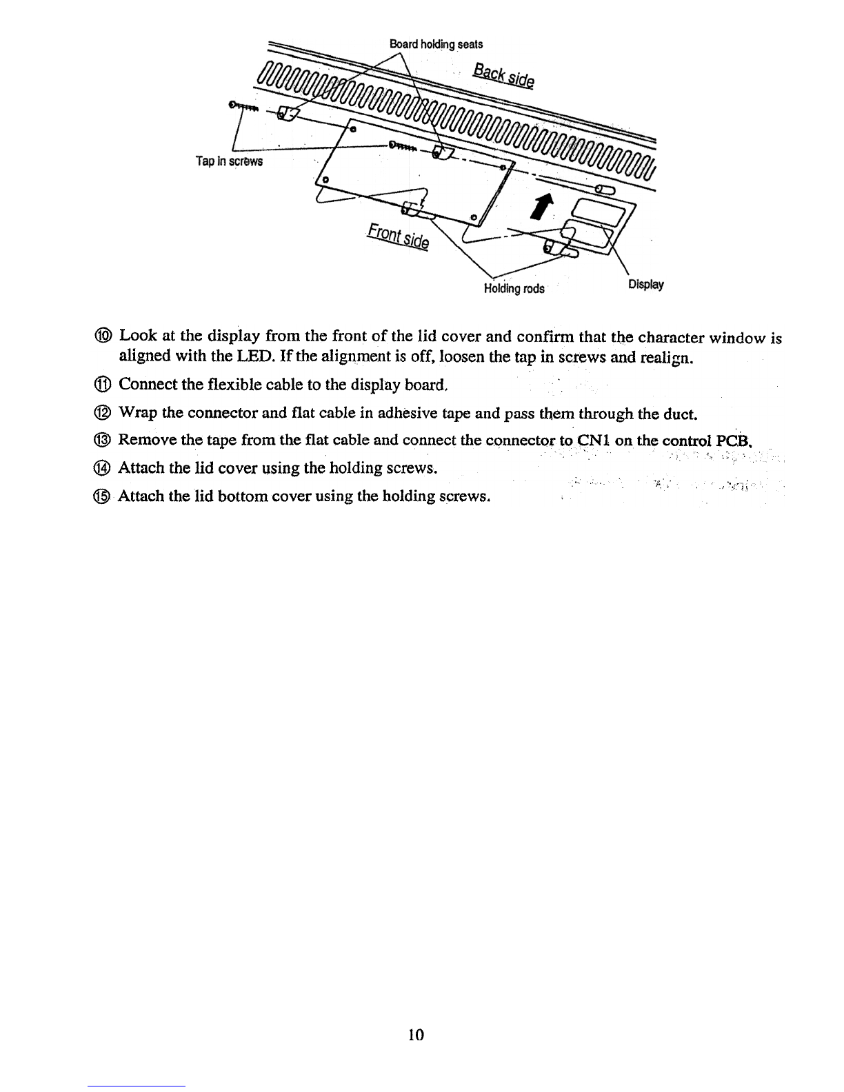
@>Look at the display from the front of the lid coverand confirm thatt~e characterwindow is
aligned with theLED. If the alignmentis off, loosenthetapin screwsandrealign.
@ Connecttheflexible cableto the displayboard,
@ Wrapthe connectorandflat cablein adhesivetapeandpassthemthroughtheduct.
@)Removethetapefrom the flat cableandconnectthe cQnnectorto~Nl onthecontrolPC.B.
!, .:: c.
@ Attach thelid coverusingtheholding screws. ..f'.. , ~..,':l{
@Attach thelid bottom coverusingtheholding screws.
10

C~aEt~~~. !roubleshooting C~art
1. ErrorDetection (Alar~5)
Disolav Cause Items to check Remed~:
Userjnstruction
I
User check
'Er1I
(Lack-oi-water
alarm)
:
User check Userinstruction
Checkcontact/open
iactivation distance
I
Lack-of-water
preventiondeviceII
replacement
Control PCB
!replacement
~- ~ --~--!
I) Water was not placed in the
.I
working chamber
2) Water was not replenishedI
durin~ continuous ~peration
3) Defectlve contact pOInt
! operation of the lack-or-waterI
prevention device
4) Defective input circuit for theI
lack-or-water prevention
device on the control PCB
5) Wiring contact problem
i between the lack-of-waterI
prevention device and the
control PCB
:
Check using the checkI
program ..c4"
;
Check wiring Wiringrepair
I
R~place sensor
1) Defectivetemperaturesensor
IEr2I
(Broken wiring
for temperature
sensorforI
control)
iReplace
control
IPCB
12) Defective input circuit for the
temperature control sensoronI
the control PCB
Measure temperature I
sensor resistance value (at
normal temperature: ,
resistance between wrute I
and yellow wires is 79 -
156 K.Q) I
Check using the check
program ..c6" (display of
47 -91 is nonnal at
normal temperatures)
Check using the check
program ., c7" (display of
175 isnonna1 a_t121°C)
[Replace
control
IPCB
Checkusingthe check
Iprogram "c3"
I
1) Defective solid state relay
(SSR) output circuit on the
I control PCB
12) Defective SSR
!Er3
I(Excessive
temperature
ialarm)
I
Replace SSRICheck contact/open
Iactivation distance
~ ---
1) Defective heateroperation
'Er4-
I(Excessive
Icoolingalarm)
I
Replace the
sensor
12) Defective temperature sensori
for control
:
Refer to trouble shooting
measures to take when the
Itemperature in theworking!
Ichamber will not rise
!Measure temperature
,sensor resistance value (at
100°C: resistance between
white and yellow wires is
Iabout 63 Kg)
11

:
,Reroed~
!;, ",,' '" crReplacetheI
control PCB
Itemsto 6tle'ck
Cause
Display Checkusingthecheck
program ..c7" (a display
valueof.92i~ ~orrnal at
100°C)
~3) Defective input qircuit for the
II temperatureconttol sensor on
the control PCB
i~r5 1) Defective solenoid-controlled
valveoperation
(Excessive
oressurealarm)
Referto troubl~ shooting
measuresto takewhenthe
,
air inth~ wor~.ng champ~r
will not purge
Checkwhetherthe contact
make/breakisdisabled,
2) Defective over-pressurization
preventionswitch
ICheck using the check
,
program..c11" (~display
I ., , .:
valueof 1or }snorm~l
iat.lQQO~)_~; ..':' "!~
Replaceover-
pressurization
prevention
switch.
'IReplace the
control PCB
3) Defective input circuit for the
over-pressurization
..prevention switchon the
contr91 PCB
ITighten
the[screws
1) Lock plateattachrilentisloose
.Er6
(Lid abnormality
alarm)
I
'I'Tighten the
screws
2) Limit switchLSWI attachment
is loose
3) befective limit switchLSWI
iCheckthe loosenessof the
lock plate attachment
screws
Checkthe loosenes
limit switchLSWl
attachmentsCrews:
Checkcontact/open
activationdistance
Check using the check
program ".c4"
Replacethe limit
switch
Replacethe
control PCB
4) Defective input circuit for
limit switchLSWI on the
control PCB
Same as ..Er4."
IEr9
(Sterilization
1eaterabnormal-
ity alarm)
"~rL 1) Limit switchLSW2attachment
is loose ITighten screW$
(Open!closelever
lock abnormality
alarm) 2) Defective limit switchLSW2
Checkthe loosenessof theI
limit switchLSWl)
iattachment
Check contact/open
activation distance
Checkusing the check
,program "c4)"
!Replace
iswitch
i
IReplaceiPa;J
Checkthe loosenessof the
solenoid !Tighten screws
3) Defective input circuit for
limit switchLSW2) on the
control PCB14)
'Sole~oid attachment loose
12
limit
control

Disolav Cause Items to check Remedy
15) Defective solenoid of 4X
r~lay
IReplace
defective
parts,
!
Check using the check
Iprogram ..c3"
User check
I
User instruction
IErEI
(Exhaust bottle
abnormalityI
alarm)I
:Tighten screwsI
1) Exhaust bottle was
removed during
operation or while thei
pressure in the working
, chamber wasO.5kgf/cm2I
or more
2) Limit switch LSW3I
attachment is loosei
3) Defective limit switch
LSW3
4) Defective input circuit for
II limit switch LSW3 on the
control PCB
i
Check looseness of limit
switchLSW3)I
Check contact/open activation
distanceII
Check using the check
program "c4"
Replacei
switch,ReplaceI
PCB
2. EarlyTroubleshooting
I
Condition
,I
Displays do not
light whentheI
power switch
j(breaker) is
turnedon.
Cause Itemsto check Remedy
I
Repajr or replace'i
defective parts
1) Poor connection or
contact atterminalsand
connectors
iC~;ctili~---
Iproblem with the
facilities
:Replace the
I power cord
Replace the
'breaker
iReplace the
I transformer
L12) No power
jPower cord connection IBreaker (power switch)
connection ,
Tab tenninal connection I
Connection of CN2connector
on the control PCB
Connecl:ion of CNl)
connector on the control PCB
Power socket (rated voltage)
3) Powercord brokenI
iPower
sideof breaker(rated
voltage)I
Breaker load (rated voltage)
14) Breaker broken
I5) Transformerbroken
ICheck, repair, ori
replace the shoft
Replace theI
control PCB
jCorrect theI
reason for the
blown fuse and
replace the fuse
Between terminals 1 and 2 onl
Iconnector CN1 on the control IiPCB
(AC14V)
Between terminals 12V and I
IOV (DC+12V)
[Between terminals 5V and OV
(DC+5V)I.
Check visually
'6)
Defective parts in the
i control PCB
i7) Defective parts in the
control PCBI
8) Blown fuse in the control
I PCB .
13
limit
control

itemstocheck
Condition
L..
One digit on the
LED displaydoes
not light
Pressurein
working chamber
will not rise
1) Defective circuit i: LED s~ldering points
2) Defective LED LED broken ",
Leak from safe~y valve,: ~.
1) I?efect:ive safety valve
Pressuregaugeneedle
2) Brokenpressuregauge
Steamleaksfrom piping
3) Piping loose or damaged
;RemedY.
Rep~r 'soldering
poin;ts
Replace;LED
",' '.,
Rep~ror replace
safetyvalve':"':
Replacepressure'
gauge
, Rep,~r leaking
.
,.--~ 1s!cj1~~4) Refer to trouble shooting section
, ~ "
1) Refer to trouble shooting section
Air not purged
from working
chamber
Steamleakfrom
the lid gasket
iE;
.'
I) Old or damaged lid gasket Visually check the Replac~ the lid
deterioration and damage to gasket : ;,c"
the gasket ,
Visually check the , "
attachment evenly:,
i
Visually check for foreigtt Remove,
matter adhering to the lid or colltamina~t~: " ,
lid gasket ".,",'~,'"
2) Improper lid gasket
attachment
3) Adhering foreign matter
'!:".;;i:
:;,..,
.;: !
Waterleak form
thebottomof the
body
1) Leak from heater
attachmentnut section
Ti$hten .i ' c',,:'
attachmentnuts";'
Rep1acegasket
Tighten
a~t.achmentnuts
2) Leak from lack-or-water
preventiondevice
attachmentnut section
3) Leak from piping
4) Leakfrom exhaustbottle
Loosenessof heater
attachmentnuts
Gasketdeterioration
Loosenessof lack-or-water
prevention device attacp~ent
tnu s !.
Piping looseness
Damageto exhaustbottle
Cracksin exhausthose
5) Leak from exhausthose
Stateof the exhaustvalve
Tightenpiping
Replaceexhaust
bottle
tReplaceexhaust
hose
Closeexhaust
valve
6) Leak from exhaustport
dueto openexhaustvalve,
if:- Referto the trouble shooting section
Open/closelever
will not move
Lid will not raise 1) Open/closeleveris not Check lever position (right Slide lever
or lower completely to one side end) completely to the
--right end
14
Cause ,
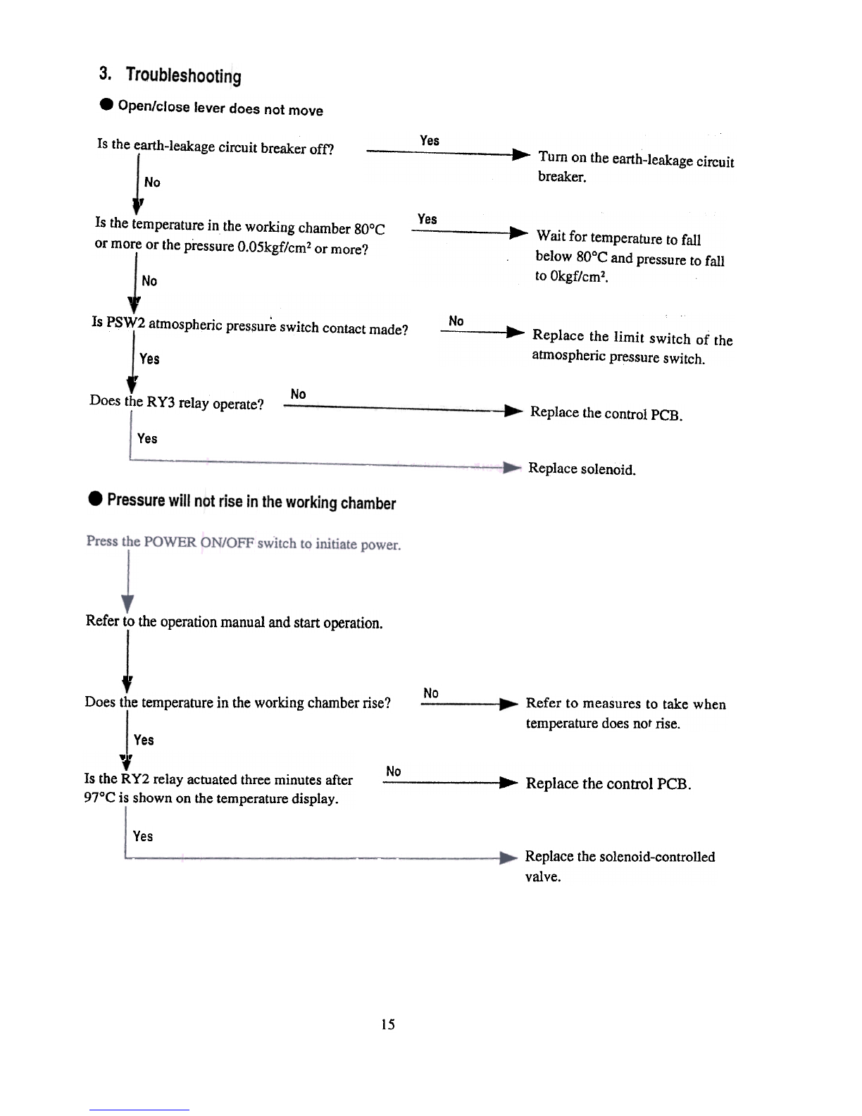
3.
.Open/close lever does not move
Is thee;arth-leakagecircuit breakeroff? Yes
~ ...Turn on the earth-leakage circuit
breaker.
No
,
Is thetemperaturein theworking chamber80°C
ormore or thepressureO.O5kgf/cm2or more?
I
Yes Wait for temperaturetofall
below80°Candpressureto fall
toOkgf/cm2.
No
1,
Is PSW2atmosphericpres.sur~switchcontactmade? No ...Replace the limit switch of the
atmosphericpressureswitch.
Yes
,
No
DoestheRY3 relayoperate? ReplacethecontrolPCB.
Yes
Replacesolenoid.
Refert.otheoperationmanualandstartoperation.
.
No
Doesthetemperaturein theworkingchamberrise? Refer to measuresto take when
temperaturedoesnotrise.
Yes
..
Is theRY2 relayactuatedthreeminutesafter
97°Cis shownonthetemperaturedisplay.
No ..Replace thecontrolPCB.
Yes Replacethesolenoid-controlled
valve.
15
Table of contents
Other HIRAYAMA Laboratory Equipment manuals


Popular Laboratory Equipment manuals by other brands

MELAG
MELAG MELAquick 12+ p user manual

Barnstead International
Barnstead International DIamond 1265 Series Operating manual and parts list

Buchi
Buchi B-811 Operation manual

REPLIGEN
REPLIGEN TangenX PRO PD LHV user guide

Helmer Scientific
Helmer Scientific i.Series Service and maintenance manual

Civco
Civco GUS G32-S Operator's manual

Chopin
Chopin Alveo PC graph Quick installation and first test

Thermo Scientific
Thermo Scientific TSQ Endura Hardware manual

Storz
Storz 8403 XSB Instructions for use

Gilson
Gilson MyPIPETMAN Select manual

IKA
IKA ULTRA-TURRAX T 18 basic operating instructions

Shimadzu
Shimadzu LC-40D X3 CL instruction manual


