HIRAYAMA HV-25 User manual

Artisan Technology Group is your source for quality
new and certied-used/pre-owned equipment
• FAST SHIPPING AND
DELIVERY
• TENS OF THOUSANDS OF
IN-STOCK ITEMS
• EQUIPMENT DEMOS
• HUNDREDS OF
MANUFACTURERS
SUPPORTED
• LEASING/MONTHLY
RENTALS
• ITAR CERTIFIED
SECURE ASSET SOLUTIONS
SERVICE CENTER REPAIRS
Experienced engineers and technicians on staff
at our full-service, in-house repair center
WE BUY USED EQUIPMENT
Sell your excess, underutilized, and idle used equipment
We also offer credit for buy-backs and trade-ins
www.artisantg.com/WeBuyEquipment
REMOTE INSPECTION
Remotely inspect equipment before purchasing with
our interactive website at www.instraview.com
LOOKING FOR MORE INFORMATION?
Visit us on the web at www.artisantg.com for more
information on price quotations, drivers, technical
specications, manuals, and documentation
Contact us: (888) 88-SOURCE | sales@artisantg.com | www.artisantg.com
SM
View
Instra

Artisan Technology Group - Quality Instrumentation ... Guaranteed | (888) 88-SOURCE | www.artisantg.com

Introduction
We would like to express our gratitude for your purchase of our autoclave. This brochure covers
the operation method and a simple maintenance method for the Autoclave
HV-25/50/85/110
you
now own. We hope that owing to your proper handling the autoclave can demonstrate its full
performance and that you
will
make regular use of it for a long time.
For
optional equipment
(0
printer,
O
floating sensor,
0
cooling fan, automatic water supply
equipment),
if
any, read the attached operation manuals for the equipment.
Please check whether or not the product conforms to your order and confirm that it was not
damaged during transportation, Should it be damaged or out of order, please contact the sales
outlet from which you purchased it.
Be
sure to send the enclosed warranty registration card to us.
+\\\\\\\\\\\\\\\\\\\\\\\\\\\\\\\\\\\\\\\\\\\\\\\\\\\\\\\\\\\\\\\\\\\\\\\\\\\\\\\\\\\\\\\\\\\\\\\\\\\\\\\\\\\\\\\\\\\\\\K
2
Q
(1)
No
part
of this document may be reproduced without permission.
+
Q
(2)
The contents of this document are subject to change without notice.
Q
2
(3)
This document has been carefully compiled. If you have
any
questions or necessary
t
$
information uncovered
in
the
document, please contact us
or
the sales outlet from which
?
$
you purchased the product.
k\\\\\\\\\\\\\\\\\\\\\\\\\\\\\\\\\\\\\\\\\\\\\\\\\\\\\\\\\\\\\\\\\\\\\\\\\\\\\\\\\\\\\\\\\\\\\\\\\\\\\\\\\\\\\\\\\\\\\\~:
Table
of
Contents
Date Descriptionof Revision
Jun.
11, 1996
Additions and revisions to
WARNING,
CAUTION and NOTE.
Instructions under "Replacing Lid Packing" in Chapter
4:
Maintenance and Service revised.
Instructions for "Operation with
a
WaSte Disposal Bag" added.
Instructions for "Successive Operations with the Product" added.
Artisan Technology Group - Quality Instrumentation ... Guaranteed | (888) 88-SOURCE | www.artisantg.com
Before
Using
In this manual the following headwords are applied to items to which great attention should
be
given:
WARNING:
Precaution indicating an imminent dangerous situation which if not avoided
may lead to death or serious injury.
a
CAUTION:
Precaution indicating a dangerous situation which if not avoided may lead to
moderate or slight injury.
IMPORTANT:
Indicates items you are strongly advised to obey.
NOTE:
Items you should pay attention to during operation.
r
/(\
WARNING
Never use the autoclave to sterilize the following dangerous objects or substances containing
alkali content. Sterilization of such objects may cause explosion, corrosion of the working
chamber or piping, and deterioration in packing.
/
List
of Dangerous Objects:
(1)
Explosive substances
Nitroglycol, nitroglycerin, nitrocellulose, and other explosive nitric esters.
*Trinitrobenzene,trinitrotoluene, picric acid, and other explosive nitro compounds.
*Peraceticacid, methyl ethyl ketone peroxide, benzoyl peroxide, and otherorganicperoxides.
(2)
Ignitable substances
*Metallic lithium, potassium, sodium, yellow phosphorous, phosphorus sulfide, and red
phosphorus
Celluloids, calcium carbide (carbide), lime phosphide, and magnesium powder
Aluminumpowder, magnesium powder, and metallic powders otherthan aluminum powder
*Sodium.dithionite(or sodium hydrosulfite)
(3)
Oxidizer
*Potassiumchlorate, sodium chlorate, ammonium chlorate, and other chlorates
Potassium perchlorate, sodium perchlorate, ammonium perchlorate, and other perchlorates.
*Potassiumperoxide, sodium peroxide, barium peroxide, and other inorganic peroxides
*Potassiumnitrate, sodium nitrate, ammonium nitrate, and other nitrates
Sodium chlorite and other chlorites
Calcium hypochlorite and other hypochlorites
(4)
Inflammable substances
Ethylether, gasoline, acetaldehyde, propylene oxide, carbon disulfide, and other substances
whose flash points range from
-30°C
to
0°C
exclusive.
*Methanol,ethanol, xylene, benzyl acetate (or amyl acetate), and other substances whose
flash points range from
0°C
to
30°C
exclusive.
Kerosene, gas oil,turpenineoil, isopentyl alcohol (orisoamyl alcohol), acetic
acid,
and other
substances whose flash points range from
30°C
to
65°C
exclusive.
Artisan Technology Group - Quality Instrumentation ... Guaranteed | (888) 88-SOURCE | www.artisantg.com
(5)
Harnmable gas (hydrogen, acetylene, ethylene, methane, ethane,propane, butane, and other
substances that are
gas
at
a
temperature of 15°C at 1atmospheric pressure.)
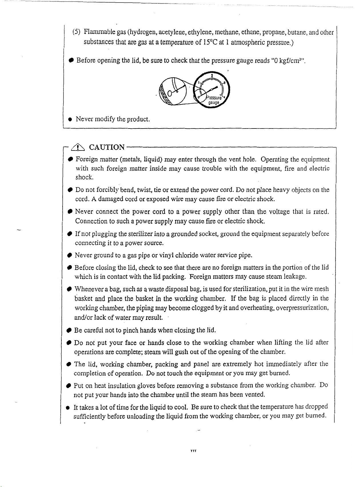
Before opening the lid,
be
sure to check that the pressure gauge reads
"0
kgf/cm2".
I
0
Never modify the product.
-
A
CAUTION
Foreign matter (metals, liquid) may enter through the vent hole. Operating the equipment
with such foreign matter inside may cause trouble with the equipment, fire and electric
shock.
Do not forcibly bend, twist, tie or extend the power cord. Do not place heavy objects on the
cord.
A
damaged cord or exposed wire may cause fire orelectric shock.
Never connect the power cord to a power supply other than the voltage that is rated.
Connection to such a power supply may cause fire or electric shock.
If
not plugging the sterilizerinto a grounded socket, ground the equipment separately before
connecting it to a power source.
Never ground to a gas pipe or vinyl chloride water servicepipe.
Before closing the lid, check to see that there are no foreign matters in the portion of the lid
which is in contact with the lid packing. Foreign matters may cause steam leakage.
Whenever
a
bag, such
as
a
waste disposal bag, isused for sterilization,put it in the wire mesh
basket and place the
basket
in
the working chamber. If the bag is placed directly in the
working chamber, the piping may become cloggedby itand overheating, overpressurization,
and/orlack of water
may
result.
,
Be careful not to pinch hands when closing the Iid.
Do not put your face or hands close to the working chamber when lifting the lid after
operations are complete; steam will gush out of the opening of the chamber.
The lid, working chamber, packing and panel are extremely hot immediately after the
completion of operation. Do not touch the equipment or you may
get
burned.
Put on heat insulation gloves before removing a substance from the working chamber. Do
not put your hands into the chamber until the steam has been vented.
@
It takes
a
lot of timefor the liquid to cool. Be sureto check that the temperature has dropped
sufficiently before unloading the liquid from the working chamber, or you may get burned.
Artisan Technology Group - Quality Instrumentation ... Guaranteed | (888) 88-SOURCE | www.artisantg.com

Do not unload the exhaust bottle or drain the working chamber when the chamber is under
pressure. Boiling water or steam may gush out, and
you
may get burned.
a
Do not unload the exhaust bottle before water in the bottle has been sufficiently cooled.
0
Do not dispose of used batteries in fire; they may explode.
a
If you encounter any anomaly
(e.g.
abnormal sound
and
smell, smoking), immediately shut
off power. After checking to see that the abnormal condition is not continuing, call us or our
authorized sales outlet from shich
you
purchased
it.
0
If the display differsbetween the steps, turn off the
POWER
switch, and then turn the power
on again.
If
the condition still remains, turn off the power and call us or our authorized sales
outlet from which
you
purchased it.
a
If
the equipment is installed in a place which is
800
m
or higher than sea level (i.e. under low
pressure
in
mountain areas), the over pressure preventive device and the air vent device
require changes to their setting.
In
this case, be sureto contact us. Do not use theequipment
before changing the setting.
a
In transporting the equipment, put the lid on and slide the open/close lever
to
the end of the
close side to prevent the lid from opening.
When moving the
lid,
do not hold it
by
the handle, otherwise the lid may become difficult to
close.
Artisan Technology Group - Quality Instrumentation ... Guaranteed | (888) 88-SOURCE | www.artisantg.com
How
to
Read
This
Manual
a
This operation manual consists of the following sections covering the information required for
proper operation ofthe autoclave
HV-25/50/85/110:
Chapter
1.
What IsAutoclave
HV-25/50185/11O?"
This section describes the uses and features of the product and the names
and
functions of its
parts.
Chapter
2.
Installation
This
sectionexplains where the equipment should be installed and how to install it.
The
product
incorporates precision parts. Be sure to follow the instructions covered in this document.
Chapter
3.
Operation Method
This section illustrates how to change various set values,
and
describes operation before starting
the equipment and after automatic operation. This section also covers the display and action of
the equipment during automatic operation.
Chapter
4.
Maintenanceand Servicing
This section explains the methods for draining water from the exhaust bottle or working charn-
ber, servicing the body, and parts replacement.
Chapter
5.
Specifications
his
section includes dimensions, power consumption, working range, piping and wiring dia-
grams of the product. Refer to this section as is required.
Chapter
6.
Inthe Event
of
Suspected Failure
This section covers troubleshooting procedures for the product. If you encounter anything sus-
pected to be due to failure, read this section first of
all.
Artisan Technology Group - Quality Instrumentation ... Guaranteed | (888) 88-SOURCE | www.artisantg.com
Contents
Introduction
...................
..
............................................................................................
Table of Contents
.........................................................
....................................
BeforeUsing
...............................................................................................................
How to ReadThis Manual
...................
....
.................................................................
Contents
....................
...
..............................................................................................
...........................................................
Chapter
1
.
What Is Autoclave
HV-25/50/8511lo?
.................................................................................................................................
1
.
Product Uses
2
.
Product Features
..........................................................................................................................
3
.
Name and Functions of Each Part
.............................................................................................
Chapter
2
.
Installation
...................
...
.......................................................................
1
.
InstallationInstructions
...........................
....................................................................................
2
.
InstallationProcedure
................................................................................................................
Chapter
3
.
Operation Method
...................
......
.........................................................
Basic Operation Method
...........................................................................................................................
Turning
"ON"
POWER Switch
....................................................................................................
PouringWater
...............................................................................................................................
Loading Substance
.......................................................................................................................
Selecting Mode (Process)
............................................................................................................
Changing Set Values (RegisteringValues
by
Customer)
.............................................................
Checking andCorrectingthe ClockTime
...................................
....
...............................................
Checking and Setting of Turn-onTimer
......................................................................................
StartingOperation
........................................................................................................................
Unloading
......................................................................................................................................
10
.
After Completionof Operations
..................................................................................................
11
.
To Interrupt Operation
................................................................................................................
12
.
If Power Supply Is Cut Off during Operation
...................
..
.......................................................
13
.
Operatjonof Cycles
...................
..
.......................................................................................
Chapter
4
.
Maintenance
and
Service
.............................................................................
1
.
DrainingExhaust Bottle
...................
A
....................................................................................
2
.
DrainingWorking Chamber
...........................
............
....................................................................
3
.
Cleaning Working Chamber
.......................................................................................................
4
.
Body Service
................................................................................................................................
5
.
ReplacingLid Packing
...................................................................................................................
6
.
Replacing Backup Battery
........................................................................................................
Chapter
5
.
Specification
...................
..
.....................................................................
Chapter
6
.
Inthe Event
of
SuspectedFailure
.................................................................
1
.
Error Detection (Alarming)Operation
...................
..
......
..
......................................................
2
.
EarlyTrouble Shooting
....................................
....
..........................................................................
Artisan Technology Group - Quality Instrumentation ... Guaranteed | (888) 88-SOURCE | www.artisantg.com

Cha~ter
1.
What
Is
Autoclave
HV-25/50/85111O?
1.
Product
Uses
This product is designed for research use only (Modes
1
-
3).
It is not labeled or marketed
for
use in medical
or
clinical applications.
This product is also used to liquefy media (Mode
4).
Mode 4 can also be used to prewarm the
chamber for a faster start.
2.
Product Features
This product is equipped with
a
cover for the lid that may be heated at hlgh temperature during
use.
Theproduct incorporates an automatic timer which permits you to begin operation at any desired
time within a period of one week.
The product is provided with a variety of modes of operation. The modes are divided into two
broad categories: Sterilization-warming mode and liquefaction mode.
If
you do not take out the
sterilized medium immediately, then select the sterilization-warming mode, and coagulation is
prevented. To liquefy a coagulated medium, use the liquefaction mode.
This autoclavecan be set to automatically exhaust
%
inside the chamberat a desired rate (exhaust
valve aperture) after sterilization is over.
Optional equipment (printer, floating sensor, cooling fan, automatic water supply equipment)
can be installed onto the product at a later date.
3.
Name and Functions
of
Each Part
Outer View of Body
When the lid is open
Lid
nT
Magnetcatch
!I:er switch
-
%
Pressure gauge
Front View
Port
for
attaching
printer
Exhaustbottle
-,..-
El-
Drain port,
Water receiver Panel
Lid
gasket Workingchamber
\
Comer plate
I
Vent hole
arrying handle
Side
View
11
(2
pieces
for
HV-85
Exhaust
port'
lo)
Rear
View
fa
Artisan Technology Group - Quality Instrumentation ... Guaranteed | (888) 88-SOURCE | www.artisantg.com
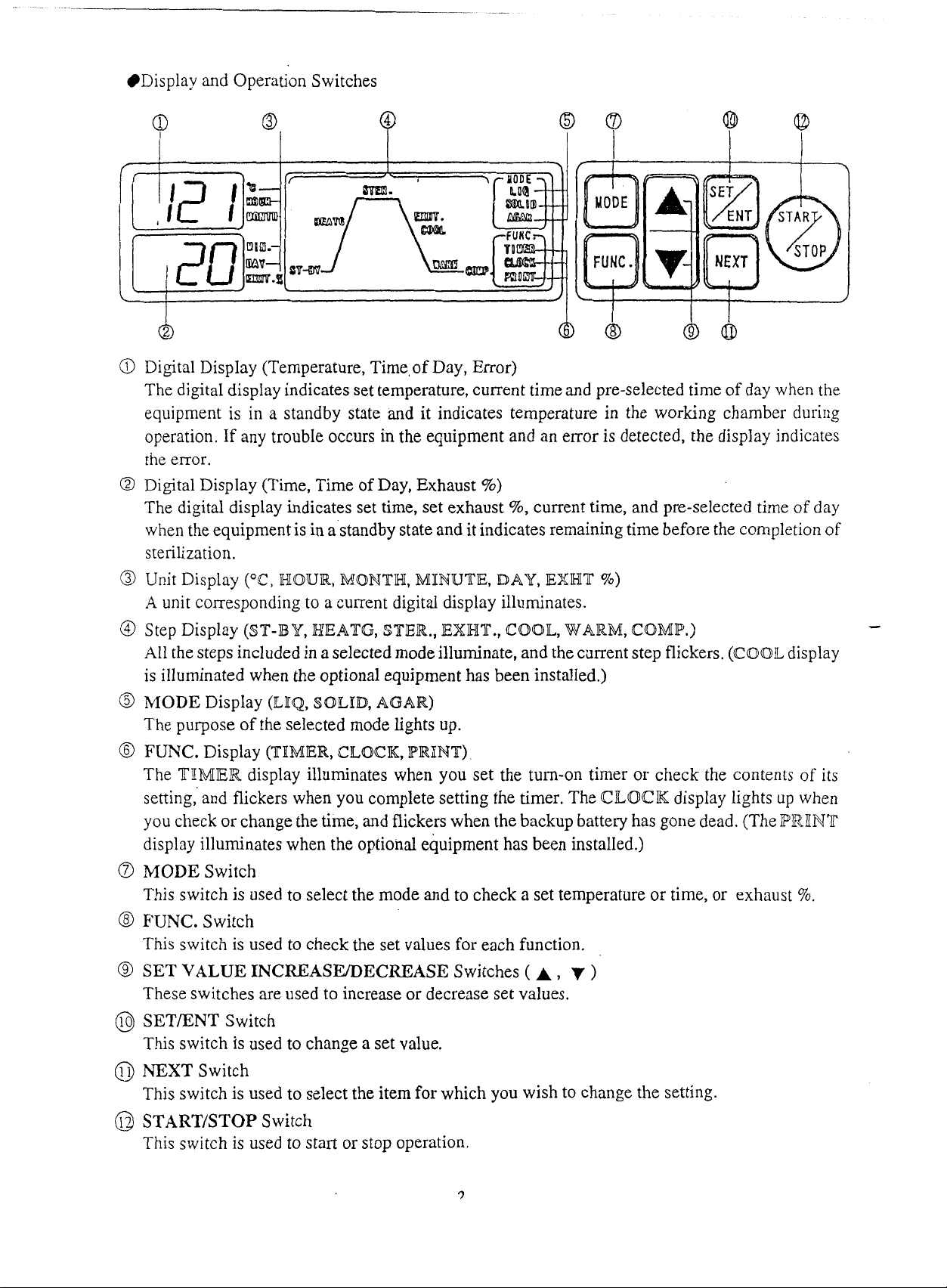
Display and Operation Switches
@
Digital Display (Temperature, Time,ofDay, Error)
The digital display indicates set temperature, current time and pre-selected time of day when the
equipment is in a standby state and it indicates temperature in the working chamber during
operation.
If
any troubIe occurs in the equipment and an error is detected, the display indicates
the error.
@
Digital Display (Time, Time of Day, Exhaust
%)
The digital display indicates set time, set exhaust
%,
current time, and pre-selected time
of
day
when the equipmentisin a'standbystate and itindicatesremaining time before the completion of
sterilization.
@
Unit Display
("C,
HOUR, MONTH, MINUTE,
DAY,
EWHT
%)
A
unit corresponding to a current digital display illuminates.
@
Step Display (ST-BY, HIEATG, $TIER., EXWT., COOL,WARM,
COMP.)
-
All the steps included in a selected modeilluminate,and the current step flickers. (COOLdisplay
is illuminated when the optional equipment has been installed.)
6)
MODE
Display
(ILIQ,
SOILID,
AGAR)
The purpose of the selected mode Lights up.
@
FUNC.
Display (TIMIER,CLOCK, PRINT)
The
TIIMIER
display illuminates when you set the turn-on timer or check the contents of its
setting, and flickers when you complete setting the timer. The
CLOCK
display lights up when
you check or changethetime, and flickers when the backup battery has gone dead. (The
PRIINT
display illuminates when the optional equipment has been instalIed.)
a
MODE
Switch
This switch is used to select the mode and to check
a
set temperature or time, or exhaust
5%.
8
FUNC.
Switch
This switch is used to check the set values for each function.
@
SET
VALUE
INCREASEDECREASE
Switches
(
A,
)
These switches are used to increase or decrease set values.
@
SETENTSwitch
This switch is used to change a set value.
0
NEXT
Switch
This switch is used to select the item for which you wish to change the setting.
@
START/STOP
Switch
This switch is used to start or stop operation.
Artisan Technology Group - Quality Instrumentation ... Guaranteed | (888) 88-SOURCE | www.artisantg.com

Chapter
2.
Installation
-
A
CAUTION
If
the equipment
is
installed in
a
place which is
800
m
or higher than sea level
(i.e.
under
low
pressure in mountain areas), its specifications require to be changed. In this case,
be
sure to
contact
us.
Do
not
use
the
equipment
before
changing.
In
transporting the equipment, put the lid on
and
slide the opedclose lever to the end of the
close side
to
prevent the lid from opening.
When moving the lid, do
not
hold
it
by
the handle, otherwise the lid may become
difficult
to
close.
1.
InstallationInstructions
O
Avoid installing the equipment in a place where
its body may be exposed to water or chemicals, or
where corrosive and explosive gases may
be
produced nearby.
Q
Avoid installing the equipment in a place which is
exposed to high humidity, direct sunlight or much
dust.
O
Avoid placing the equipment directly under a fire
detector. If you open the lid immediately after
completion of operation, steam comes out of the
working chamber, and may activate the detector.
@
Arrange the equipment with a clearance of 10 cm or
wider on the right side and
12
cm or wider on the rear
sideto prevent the vent hole fiom being blocked.
I
2
cm
or
over
1
10
cm
or
over
O
Avoid installing the equipment with its rear side
located near outlets or electrical appliances as steam
comes out of the exhaustport on the rear.
@
Avoid
an
installation place which is subject to impact
orvibration.
6
Place the unit in a level,
fm
place.
@
Avoid installing in
a
place which is subjected
to
a
room temperature of
5°C
or below or
35OC
or above.
Artisan Technology Group - Quality Instrumentation ... Guaranteed | (888) 88-SOURCE | www.artisantg.com
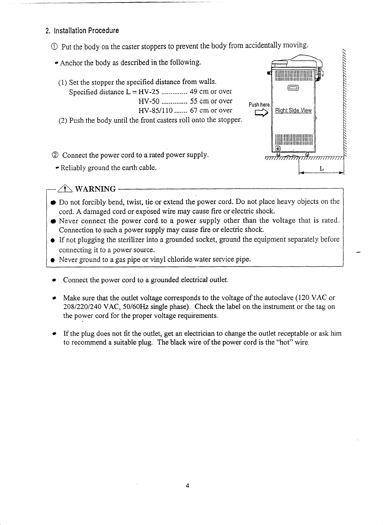
2,
Installation
Procedure
@
Put the body on the caster stoppers to prevent the body from ac
Anchor the body
as
described in the following.
(1) Set the stopper the specified distance from walls.
Specified distance
L
=
HV-25
..............
49
cm or over
HV-50
..............
55
cmor over
Push
,,
HV-85/110
.......
67
cm or over
(2)
Push the body until the front casters roll onto the stopper.
@
Connect the power cord to a rated power supply.
Reliably ground the earth cable.
w
a
WARNING
Do not forcibly bend, twist, tie or extend the power cord. Do not place heavy objects on the
cord.
A
damaged cord or exposed wire may cause fire or electric shock.
Never connect the power cord to a power supply other than the voltage that is rated.
Connection to such a power supply may cause f~eor electric shock.
0
If
not plugging the sterilizer into a grounded socket, ground the equipment separately before
connecting it to a power source.
0
Never ground to a gas pipe or vinyl chloride water service pipe.
Connect the power cord to a grounded electrical outlet.
Make sure that the outlet voltage corresponds to the voltage ofthe autoclave (120 VAC or
20812201240 VAC, 50160Hz single phase). Check the label on the instrument or the tag on
the power cord for the proper voltage requirements.
If
the plug does not fit the outlet, get an electricianto change the outlet receptable or ask him
to recommend a suitableplug. The black wire ofthe power cord is the "hot" wire.
Artisan Technology Group - Quality Instrumentation ... Guaranteed | (888) 88-SOURCE | www.artisantg.com
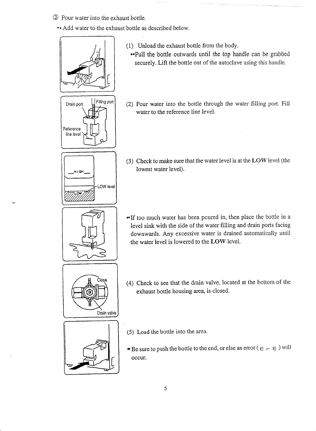
@
Pour water into the exhaust bottle.
Add water to the exhaust bottle
as
described below.
Drainpo
Pol
Reference
line
level
(1)
UnIoad the exhaust bottle from the body.
Pull
the bottle outwards until
the
top
handle
can
be
grabbed
securely.
Lift
the bottle out of the autoclave using
this
handle.
(2)
Pour water into the bottle through the water
filling
port.
Fill
water to the reference line level.
LOW
level
1
Drain
valve
(3)
Checkto make sure that thewater level is at the
LOW
level (the
lowest water level).
If
too much water has been poured in, then place the bottle in a
level sink with the side of the water filling and drain ports facing
downwards. Any excessive water is drained automatically until
the water level is lowered to the
LOW
level.
(4)
Check to see that the drain valve, located at the bottom of the
exhaust bottle housing
area,
is closed.
(5)
Load
the
bottle into the area.
Besureto pushthebottle to the end,orelse
an
error
(
E
,
E
)
will
occur.
Artisan Technology Group - Quality Instrumentation ... Guaranteed | (888) 88-SOURCE | www.artisantg.com
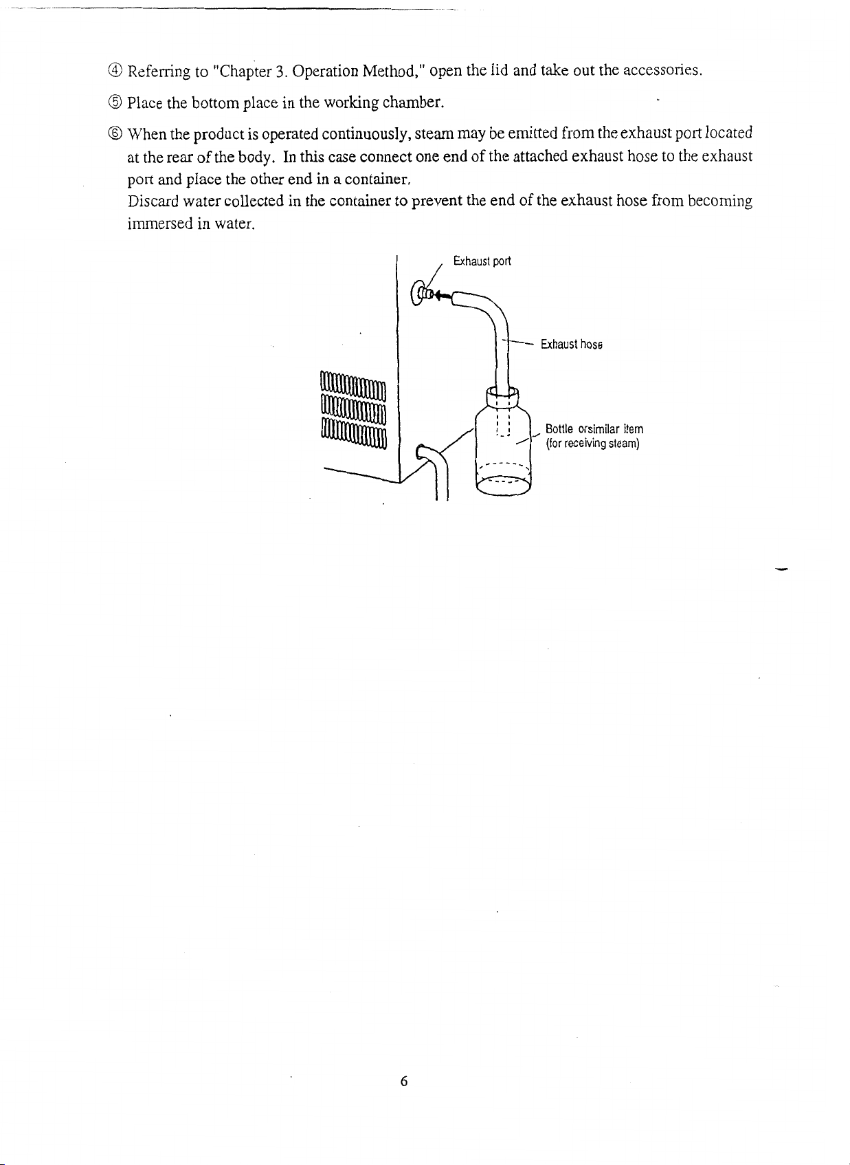
@
Referring to "chapter
3.
Operation Method," open the lid and take out the accessories.
@
Place the bottom place in the working chamber.
@
When the product is operated continuously, steammay be emitted from
the
exhaust
pon
located
at the rear of the body. In this case connect one end of the attached exhaust hose to the exhaust
port
and
place the other end in a container.
Discard water collected in the container to prevent the end of the exhaust hose from becoming
immersed in water.
Bottle orsimilar item
(for receivingsteam)
Artisan Technology Group - Quality Instrumentation ... Guaranteed | (888) 88-SOURCE | www.artisantg.com
Chapter
3.
Operation
Method
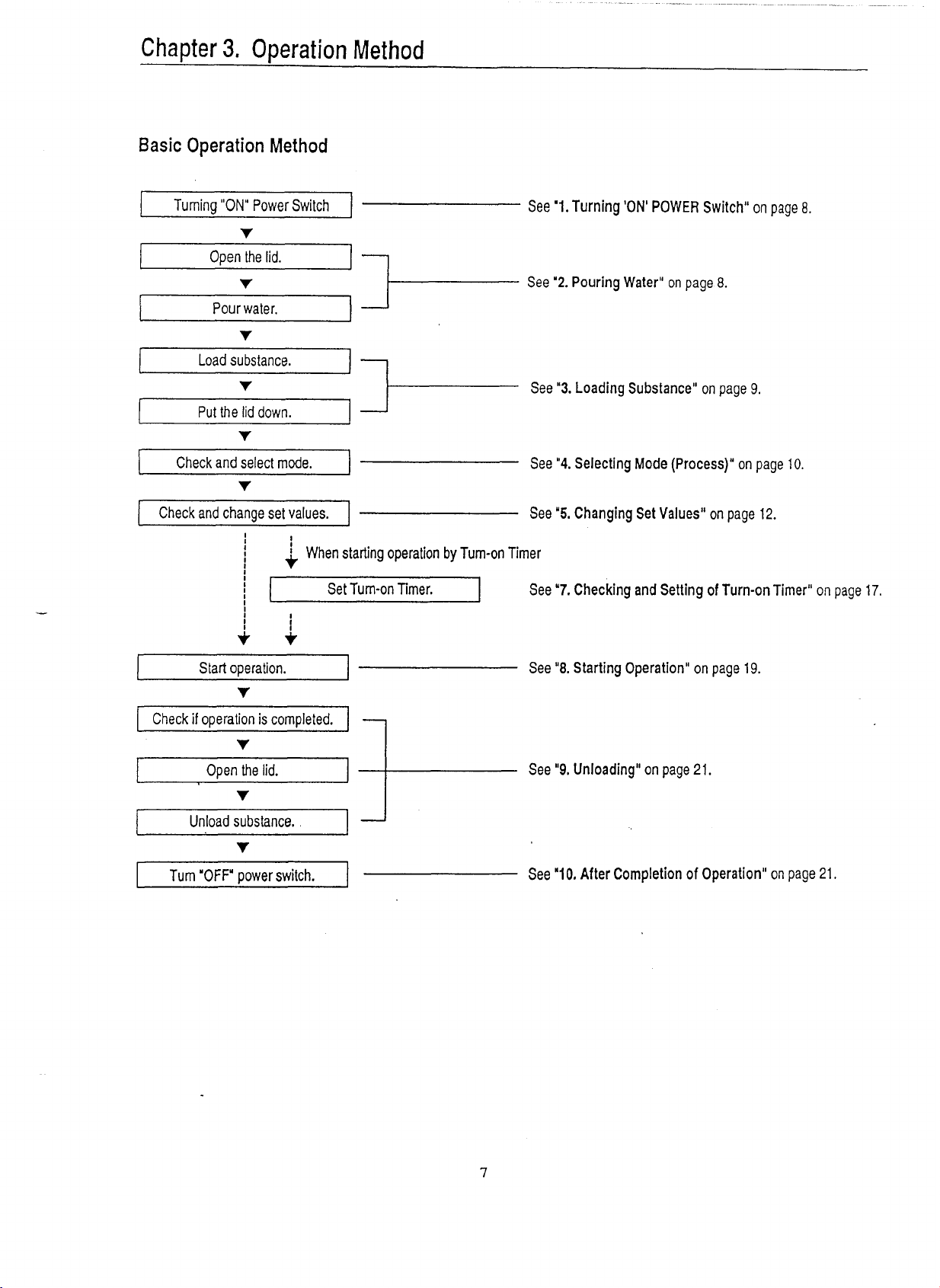
Basic
Operation Method
Turning
"ON'
PowerSwitch
1
See
'1.
Turning 'ON' POWER Switch"
on
page
8.
v
Open the lid.
I1
v
See
'2.
Pouring
Water"
on
page
8.
Pourwater.
v
i
Loadsubstance.
11
v
A-
See
'3.
LoadingSubstance" on page
9.
1
Put the lid down.
i
Check andselect mode.
-
See
"4.
Selecting Mode (Process)" on page
10.
I
Check and change set values.
1
---------
See
'5.
Changing Set Values" on page
12.
I
I
i
i
Whenstarting operation
by
Turn-onTimer
I
Start operation.
1
See
"8.
StartingOperation" on page
19.
1
I
Set Tum-on Timer.
Check
if
operation is completed.
I
v
1
Openthe lid.
I
See
"9.
Unloading"on page
21.
v
Unloadsubstance.
v
See
"7.
Checking and Setting of Turn-onTimer" on page
17.
Turn
'OFF'
powerswitch.
I
---------
See
"10.
After Completion of Operation'' on page
21.
Artisan Technology Group - Quality Instrumentation ... Guaranteed | (888) 88-SOURCE | www.artisantg.com

1.
Turning
"ON" POWER
Switch
O
Turn
ON
the
POWER
switch at the front of the body.
When the openiclose lever is set to
"LOCK"
(left side), settings light up on the display. The
autoclave is ready in this state.When the open/close leveris setto
"UNLOCK"
(anywhere other
than
on the left side),
"
L
is shown on the display.
Ready
state
2.
Pouring
Water
,
<r>.
IMPORTANT
0
In operation of
UNLOCKLOCK
lever, never fail
to
put
POWR
switch
ON.
a
Slide the open/close lever to the
UNLOCK
side (the right end).
@
Grab the handle, and lift the lid
as
shown in the figurebelow.
@
Pour water through the opening of the working chamber until you can see water through the
hole at the center of the bottom plate.
The HV-25 requires
1.5
liters ormore of water; the HV-50,2liters ormore; theHV-85,4liters or
more; and the HV-110.5 liters or more. It is also required to pour water forMode
4
(AGAR).
Artisan Technology Group - Quality Instrumentation ... Guaranteed | (888) 88-SOURCE | www.artisantg.com
3.
Loading Substance
I
Be careful not to pinch hands when closing the lid.
Check to see that the area of the lid that is to come in contact with the lid gasket
is
free
from
foreign matter before closing the lid. Foreign matter present in the area may cause the steam
leakage.
a
Whenever abag, such as a waste disposal bag, is used for sterilization,put it in the
wire
mesh
basket and place the basket in the working chamber. If the bag is placed directly in the
working chamber, the piping may become clogged by it and overheating, overpressurization,
andorlack of water may result.
A
IMPORTANT
0
Keep the lid open for
15
minutes or more between operations when the equipment is operated
continously. Check to see that the temperature in the working chamber is
50(C
or below
before starting the next operation (operating the opedclose lever).
Be sure to use the bottom plate.
-
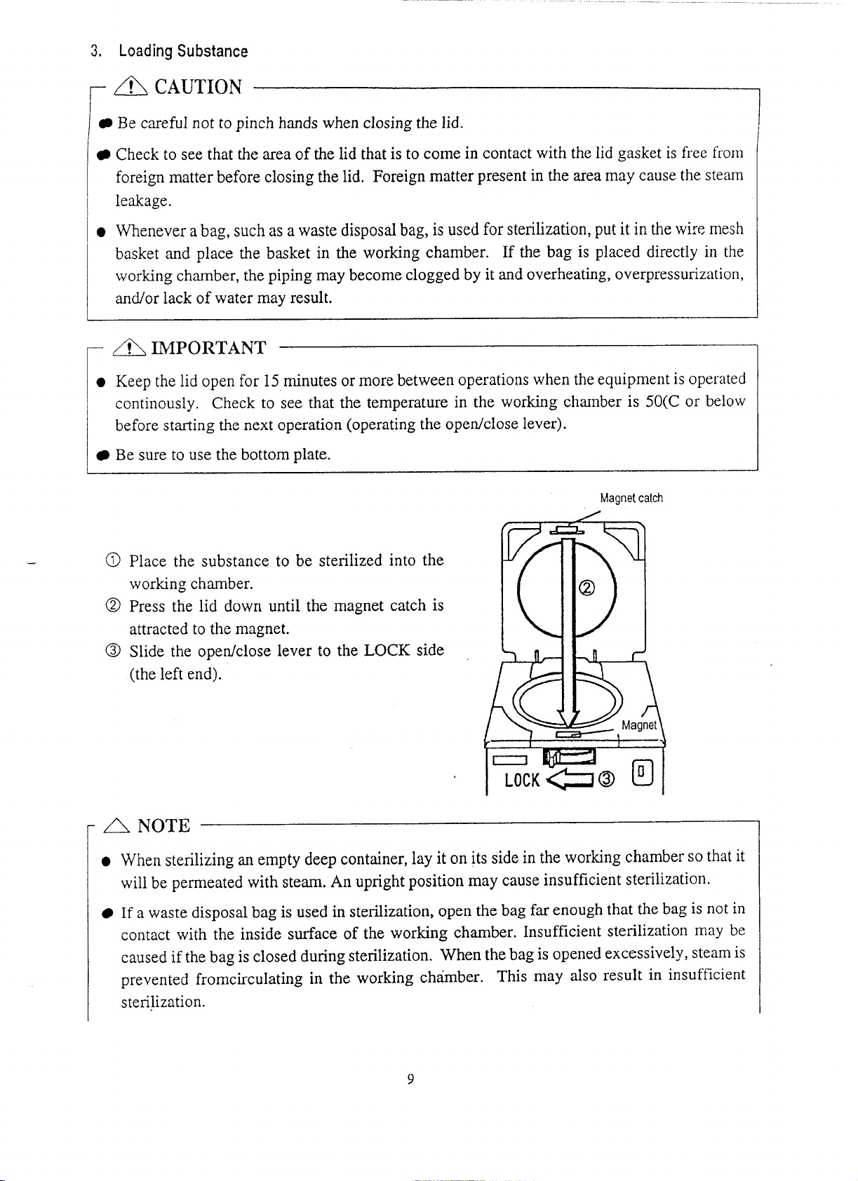
@
Place the substance to be sterilized into the
working chamber.
@
Press the lid down until the magnet catch is
attracted to the magnet.
@
Slide the opedclose lever to the
LOCK
side
(the left end).
Magnet
catch
3
y
A
NOTE
a
When sterilizing
an
empty deep container, lay
it
on its sidein the working chamber sothat it
will be permeated with steam. An upright position may cause insufficient sterilization.
If
a waste disposalbag is used in sterilization, open the bag far enough that the bag is not in
contact with the inside surface of the working chamber. Insufficient sterilization
may
be
caused if the bag is closed during sterilization. When thebag is opened excessively,steam is
prevented fromcirculating
in
the working chamber. This may also result in insufficient
sterilization.
Artisan Technology Group - Quality Instrumentation ... Guaranteed | (888) 88-SOURCE | www.artisantg.com
Do not pile specimens on top of one another. When the chamber is overly packed, steam fails
to penetrate
to
all points, resulting in incomplete sterilization.
0
In sterilizing liquids such as chemical and medium, pay attention to the quantity
of
the liquid
in relation
to
its container. For
an
Erlenmeyer
flask,
the amount of chemical should
be
approx.
314
of the capacity of the container; for
a
test tube, the appropriate quantity of chemical is
approx. half of the capacity of the container. Toomuch chemical may result in overflow from
the container during the temperature rising or coolingprocess.
When using a container, loosen the cap or use
a
breathable cap. An unbreathable cap
may
cause the container to burst.
In
the caseof liquefaction of agar medium, its quantity should be 2 liters or less per container.
Two liters
or
more of agar medium ,maynot be completely liquefied.
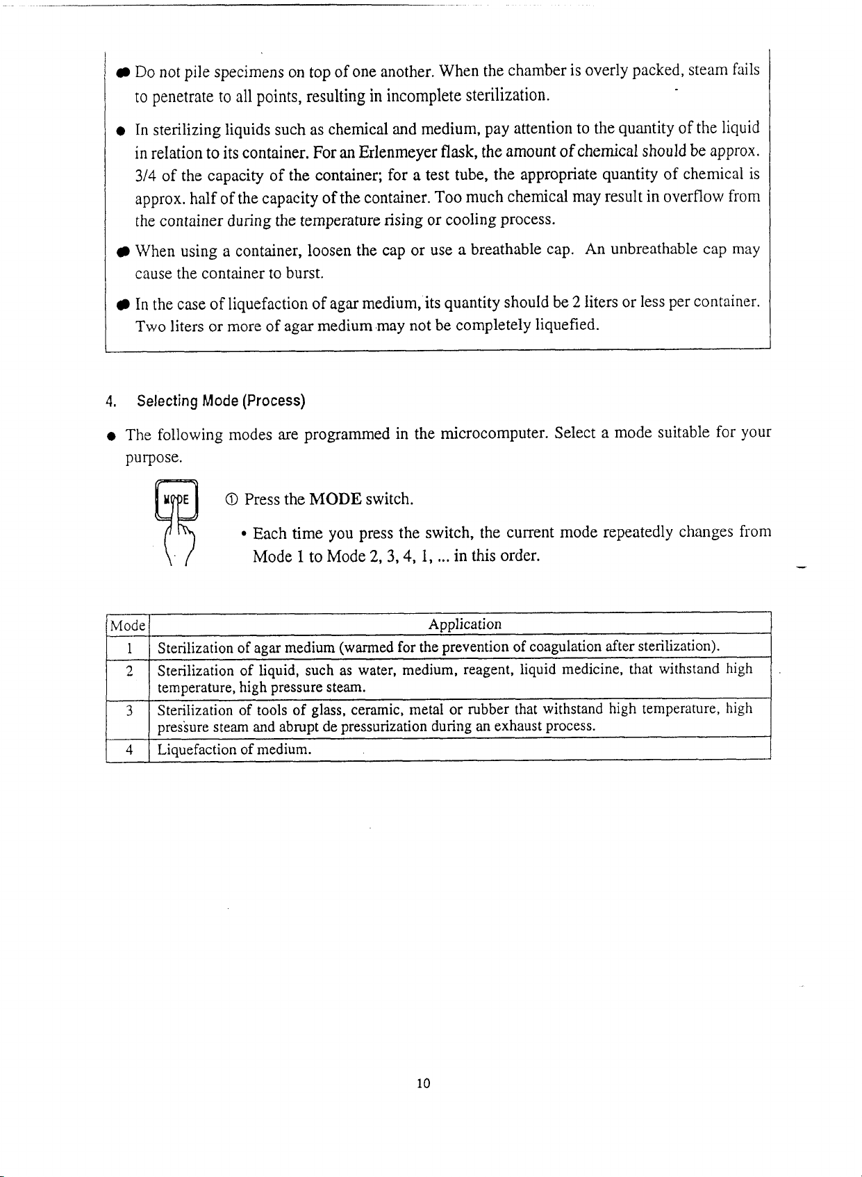
4.
Selecting
Mode
(Process)
The following modes are programmed in the microcomputer. Select a mode suitable for your
purpose.
O
Press the
MODE
switch.
Each time you press the switch, the current mode repeatedly changes from
\.
/
Mode
1
to Mode 2,
3,4,
1,
...
in this order.
Mode
1
2
Application
Sterilizationof
agar
medium (warmed for the prevention of coagulation after sterilization).
Sterilization of liquid, such as water, medium, reagent, liquid medicine, that withstand
high
3
temperature,high pressure steam.
Sterilization of tools of glass, ceramic, metal or rubber
that
withstand high temperature,
high
4
pressure steam and abrupt de pressurization during an exhaust process.
Liquefaction of medium.
Artisan Technology Group - Quality Instrumentation ... Guaranteed | (888) 88-SOURCE | www.artisantg.com

Mode
1
Mode
2
Mode
3
Mode
4
Initial Set
Value
XI-J-
Step Display
WEATG
-+
STER.
-+
EXHT.
(Varied)
-+WARM
Step Display
BEATG
-+
STEW.
-+
EXHT.
(Varied)
Alternate display
IVIUUC
Display
ILJQ
Sterilization
Temperature
12
1
OC
I
NOTE:
Lid can only
be
opened at approximately
3O
below
boiling
point.
Mode
~i~~l~~
L~Q
Initial
Set
Value
Mode
~i~~la~
XDLD
Step Display
HEATG
-+
STER.
-+
EXHT.
(Fixed)
Sterilization
Time
20 minutes
Mode
Display
AGAR
Step Display
WEATG
WARM
Exhaust
%
10%
Initial Set Value
Warming
Temperature
50
"C
Warming
Temperature
/
Sterilization
Temperatul~
121OC
Sterilization
Temperature
121OC
Initial Set Value
Exhaust
%
10%
Sterilization
Time
20 minutes
Sterilization
Time
20 minutes
W~rming
Exhaust
%
Temperature
50 OC
Sterilization
Temperature
100
OC
Sterilization
Time
10minutes
Warming
Temperature
/
Exhaust
%
/
Artisan Technology Group - Quality Instrumentation ... Guaranteed | (888) 88-SOURCE | www.artisantg.com

5.
Changing SetValues (Registering Values
by
Customer)
To change setvalues (sterilization temperature, sterilization time, warming temperature, opening
of
exhaust valve, liquefaction temperature, liquefaction time), follow the steps below: Settings
cannot
be changed while the
chamber
is running except if wanting
to
change
the
exhaust
rate
while exhausting the chamber. For details on changing exhaust rate while exhausting the
chamber, see
"Exhaust
%
during the Valve Opening Variable Exhaust Cycle"
on
pagel
8.
O
Press the
SETIENT
switch.
The display of a set sterilization (liquefaction) temperature starts
flickering. This indicates that the set value is now changeable.
O
Press the
NEXT
switch
to
select an item the setting of which you desire
to change.
*
Each time you press the switches, the changeable set items change
repeatedly as follows:
[mi
W]
Switch
Operation
NEXT
O
Change the displayed value using the setting increaseldecrease switches
(A,
v)-
Each time you press the switches, the displayed value increases or
decreases as follows:
Sterilization temperature:
In increments of
1°C
within
a
range of:
HV-25
105
-
126°C
HV-50
105
-
135°C
EN-85
105
-
135OC (105
-
128OC)*
HV-110
105
-
135OC (105
-
123OC)*
*
Specification
for
particular area
Artisan Technology Group - Quality Instrumentation ... Guaranteed | (888) 88-SOURCE | www.artisantg.com
Other manuals for HV-25
1
This manual suits for next models
3
Table of contents
Other HIRAYAMA Laboratory Equipment manuals


Popular Laboratory Equipment manuals by other brands

TSE
TSE PhenoMaster Hardware operating instructions

Live Photonic
Live Photonic Sequencer LPS-200H user manual

Diesse
Diesse cube 30 touch quick start guide

Agilent Technologies
Agilent Technologies 6475 user guide

Fluke Biomedical
Fluke Biomedical INCU Operator's manual

Hettich
Hettich ROTOFIX 32 A operating instructions


Thermo Scientific
Thermo Scientific Dionex ICS-5000 Operator's manual

Biotage
Biotage Isolera Prime user manual

caron
caron CRSY102 quick start guide

Research Instruments
Research Instruments WITNESS Installation and service manual

Oase
Oase Vitronic 11 W operating instructions

natus
natus Olympic Warmette 48 instruction manual