HIRAYAMA HV-25 User manual

Read Carefully Before Usina -
.In this manual the following headings are applied to items to which great attention should be given:
& WARNING: Precaution indicating an imminent dangerous situation which if
"& not avoided may lead to death or serious injury.
'CAUTION: Precaution indicating a dangerous situation which if not
(j'\ .av~ided ~ay lead to moderate or slight injury.
V IMPORTANT. Indicates Items you are strongly advised to obey.
& WARNING:
.Check that the pressure is below "OMpa" before opening the lid.
& CAUTION:
.Wait until the body has cooled sufficiently to perform maintenance and service work.
.Wait until the water in the bottle has cooled sufficiently to take out the exhaust bottle.
.Do not take out the exhaust bottle or drain the working chamber when the interior of th
chamber is under pressure. Otherwise, boiling water and steam will gush out, and yo
may burn yourself.
.Be careful not to cut fingers when cleaning the bottom of chamber or heater. The heate
attaches a temperature sensor and fixing clips that corners may cut your fingers.
.Do not incinerate used batteries. Incineration may cause the batteries to explode.
.Be sure to securely tighten the heater holding nuts when replacing the heater. Water ma
leak and cause short circuits if the nuts are loose.
.Be sure to securely tighten terminal holding nut A when replacing the heater. Heat ma
be generated from the terminal and burn damage may result if the nut is loose.
II

How to Read this Manual
This manual consists of the following sections covering the information required for proper
maintenance of the HV-25/50/85/11 0 autoclaves.
Chapter 1. Maintenance and Adjustment
This section describes the maintenance procedures for the unit as well as the methods for
replacing and adjusting the main parts.
Chapter 2. Troubleshooting Chart
This section describes the items to check and measures to take when a problem occurs.
Chapter 3. Product Description
This section describes the operations and internal structural parts of the product.
Chapter 4. Operation Check Procedure
This section describes the method for checking the operation of electrical parts using the check
programs.
Chapter 5. Main Parts List
The code numbers for the main pats are listed in the table here.
III
I
--
Contents
Chapter 1. Maintenance and Adjustment ""'.".' 1
1. Draining Water from the Exhaust Bottle ".""" ...1
2. Draining the Chamber. "..2
3. Cleaning the Chamber "" ,.".,..,.3
4. Cleaning the Body 3
5. Cleaning the Cooling Unit Filter " ".' ,..,..4
6. Lid Gasket Replacement '.""..' " " 5
7. Backup Battery Replacement '."...' '.'...""...6
8. Solid State Relay (SSR) Replacement '."'..."' 7
9. ROM Replacement 7
10. Heater Replacement 9
11. Temperature Control Sensor Replacement 10
12. Floating Sensor (Option) Replacement 11
13. Motor Replacement 12
14. Exhaust Valve Replacement '...'.""' 13
15. Display Board Replacement 14
16. Exhaust Valve Adjustment "..".'.."'...' 16
17. Alarm Volume Adjustment 17
18. Switchboard Replacement "".".'." 17
Chapter 2. Troubleshooting Chart ' 18
1. Error Detection (Alarms)."'.".'.""".'."".""""""""""' 18
2. Early Trouble Shooting , , 20
3. Trouble Shooting 23
Chapter 3. Product Description 25
Error Monitoring Charts , "'.""""."-~" "..'."."" 26
External Appearance , 30
Assembly Diagrams 31
Detailed Display and Operation Switch Diagram .".,.,."."."",.."""." ,.., "".,. 35
Switchboard Diagram 36
Exhaust Valve Area Diagram...' '.'..' ".'.." " 36
Solenoid Area Diagram 37
Optional Accessories Diagrams '."' '...""..'..'.'.'." '..' 38
Piping Diagram 39
:' Wiring Diagram ,..,.,.,.,.., ,.", , 40
Connector Table , 41
IV
, "",""

Chapter 4. Operation Check Procedure """""'.'.,.43
1. Check Program Outline 43
2. Check Program Startup : 44
3. Check Programs " "'..' " " '.""' ' '...".':'..." ' ' 45
Reference Table for Floating Sensor and Temperature Control Sensor 50
Pressure Sensor Reference Table "..., "...,."..,.""",..",..,.,.""",.,.., 52
V
~ , ., ,
Chapter 1. Maintenance and Adjustment
&CAUTION:
.Wait until the body has cooled sufficiently before performing maintenance and adjustment.
.Perform maintenance and adjustment after turning the power switch off.
1. Draining Water from the Exhaust Bottle
Since the water level in the exhaust bottle increases with continued operation, water must be
drained using the procedure below when water reaches the HIGH level.
ill CAur/ON:
.Wait until the water in the bottle has cooled sufficiently to take out the exhaust bottle.
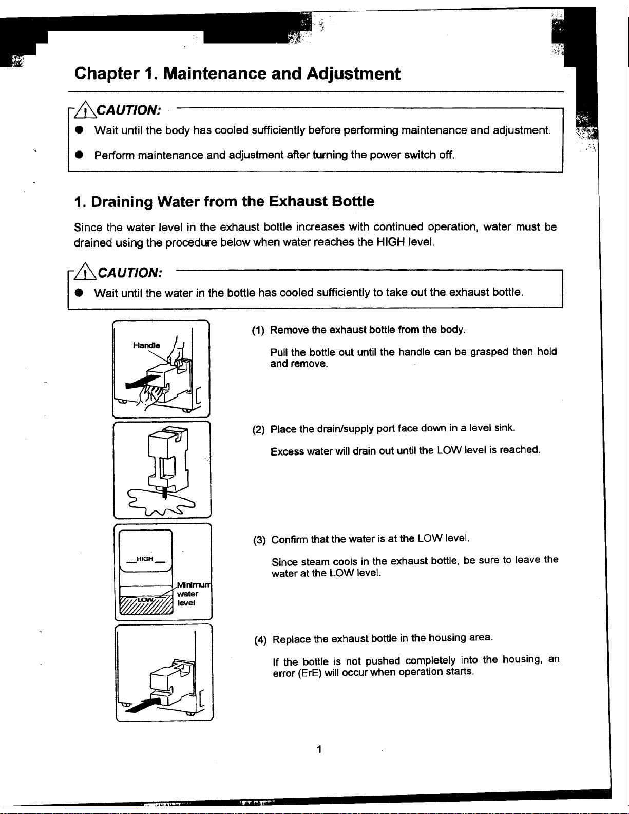
(1) Remove the exhaust bottle from the body.
Pull the bottle out until the handle can be grasped then hold
and remove.
(2) Place the drain/supply port face down in a level sink.
Excess water will drain out until the LOW level is reached.
(3) Confirm that the water is at the LOW level.
_HIGH- Since steam cools in the exhaust bottle, be sure to leave the
water at the LOW level.
(4) Replace the exhaust bottle in the housing area.
If the bottle is not pushed completely into the housing, an
error (ErE) will occur when operation starts.
1
..

2. Draining the Chamber I
Drain water using the following procedure after confirming that the inside of the chamber has
cooled sufficiently.
& CAUTION:
.Do not unload the exhaust bottle or drain the chamber when the chamber is under pressure.
Boiling water or steam may gush out causing bums.
(1) Open the lid.
(2) Connect one end of the accessory drain hose to Bottle housing area
the tap of the drain valve located at the lower Or-ainvalve nab
part of the right side of the body. Drain valve tap
kDrai n hose
(3) Put the other end of the hose in a container.
(4) Remove the exhaust bottle from the body.
(5) Turn the
drain valve knob, located at the bottom of the
exhaust bottle housing area, counterclockwise
to open.
Drain valve
(6) Check that draining of the working chamber is
complete.
(7) Turn the knob clockwise to close the drain
valve.
Be sure the exhaust valve is closed.
When drain pipes are clogged
.Connect the drain port and water pipe stopper using a pressure-resistant hose, open the
exhaust valve on the body. and gradually open the water pipe stopper. Foreign matter
clogging the exhaust piping will then flow into the working chamber. Remove the foreign
matter and drain the chamber.
.If the clog is not removed by the above procedure, disassemble the piping and clean.
.If the clog is not removed by the above procedure, disassemble the piping and clean.
2
'"' ~li.1
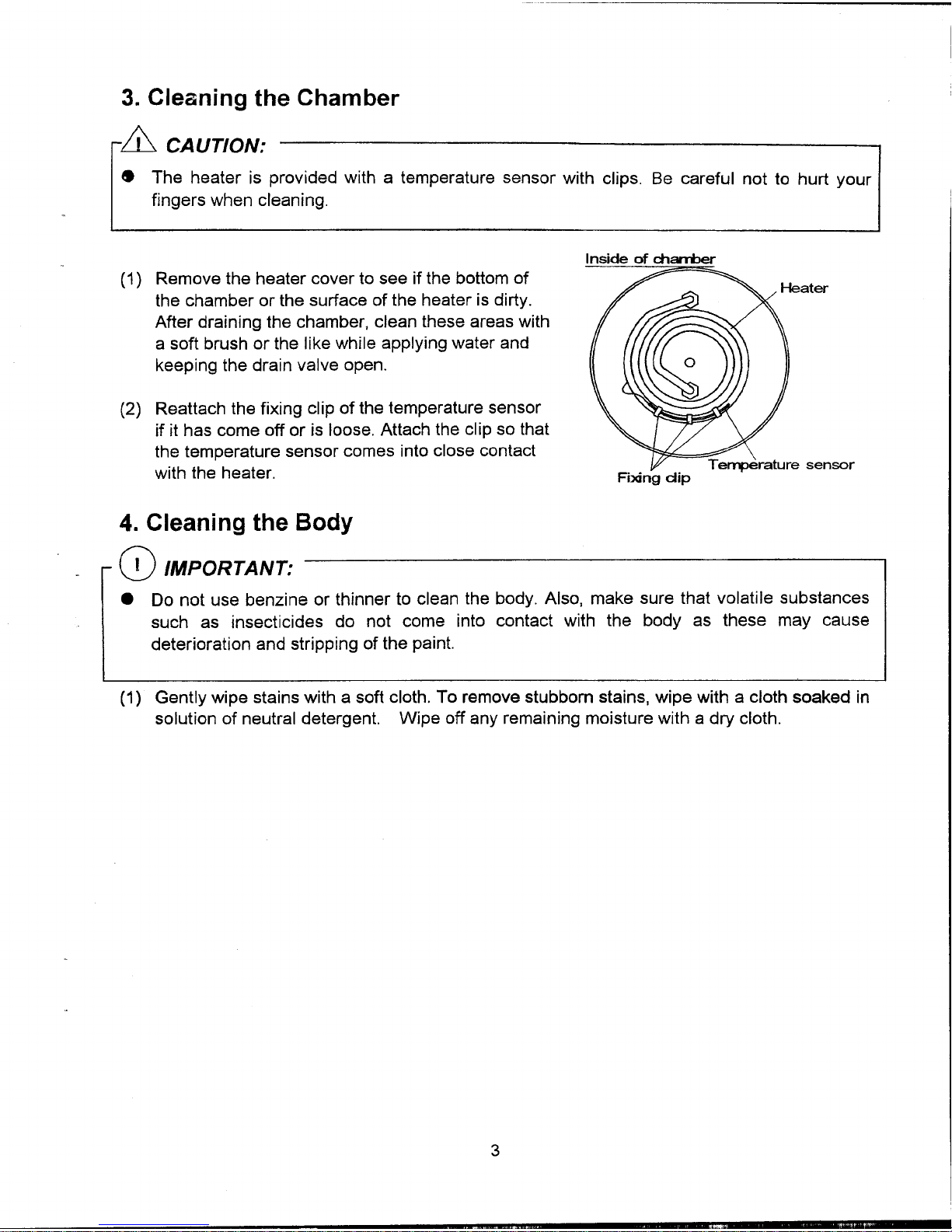
3. Cleaning the Chamber
& CAUTION:
.The heater is provided with a temperature sensor with clips. Be careful not to hurt your
fingers when cleaning.
I .
(1) Remove the heater cover to see if the bo~to~ of ater
the chamber or the surface of the heater ISdirty.
After draining the chamber, clean these areas with
a soft brush or the like while applying water and
keeping the drain valve open.
(2) Reattach the fixing clip of the temperature sensor
if it has come off or is loose. Attach the clip so that
the temperature sensor comes into close contact
.T en-perature sensor
with the heater. Fi>ongdip
4. Cleaning the Body
0 IMPORTANT:
.Do not use benzine or thinner to clean the body. Also, make sure that volatile substances
such as insecticides do not come into contact with the body as these may cause
deterioration and stripping of the paint.
(1) Gently wipe stains with a soft cloth. To remove stubborn stains, wipe with a cloth soaked in
solution of neutral detergent. Wipe off any remaining moisture with a dry cloth.
3
..
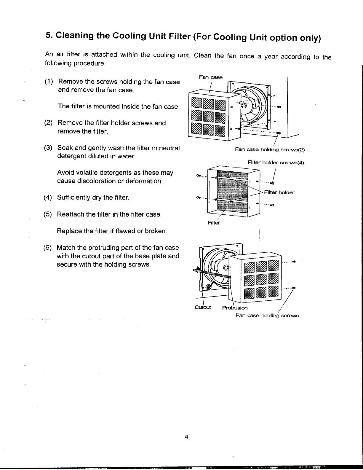
5. Cleaning the Cooling Unit Filter (For Cooling Unit option only)
An air filter is attached within the cooling unit. Clean the fan once a year according to the
following procedure.
Fancase
(1) Remove the screws holding the fan case
and remove the fan case.
The filter is mounted inside the fan case mom -~
(2) Remove the filter holder screws and I!! -
remove the filter. ~~~
(3) Soak and gently wash the filter in neutral Fancase holdingscrews(2)
detergent diluted in water. Riter holder screws(4)
Avoid volatile detergents as these may <8_. Jcause discoloration or deformation. ..-'--
Riter holder
(4) Sufficiently dry the filter. <8-. .-.~
(5) Reattach the filter in the filter case. Riter
Replace the filter if flawed or broken.
(6) Match the protruding part of the fan case
with the cutout part of the base plate and
secure with the holding screws. ommj mam
moomProtrusionY
Fan case holding screws
4
,"" "i
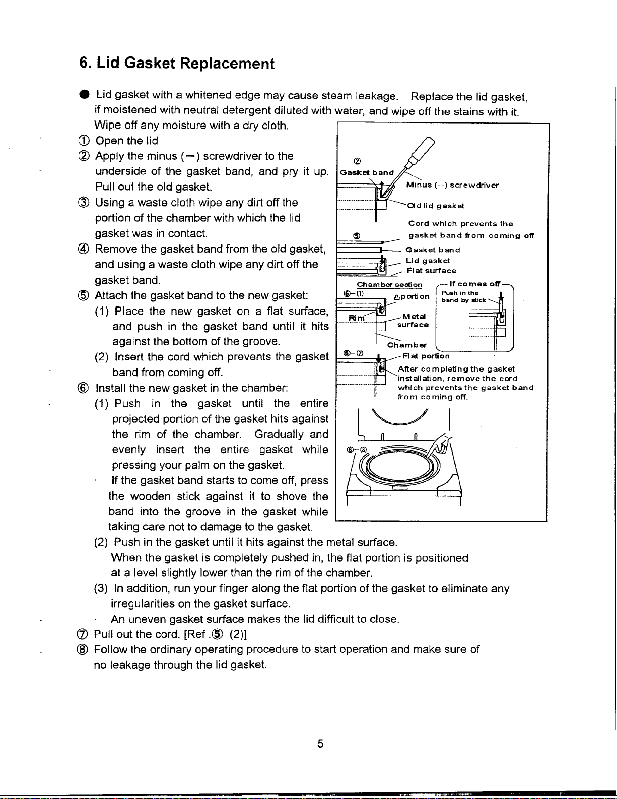
6. Lid Gasket Replacement
.Lid gasket with a whitened edge may cause steam leakage. Replace the lid gasket,
if moistened with neutral detergent diluted with water, and wipe off the stains with it.
Wipe off any moisture with a dry cloth.
CD Open the lid
~ Apply the minus (-) screwdriver to the (2)
underside of the gasket band, and pry it up. Gask
Pullout the old gasket. -) screwdriver
~ Using a waste cloth wipe any dirt off the , Old lid asket
g
portion of the chamber with which the lid Cd h .h t thor w IC preven s e
gasket was in contact. (S) gasket band ti"om coming off
@ Remove the gasket band from the old gasket, Gasket band
and using a waste cloth wipe any dirt off the Lid gasket
Flat surface
gasket band. Chamber section If comes off
@Attachthegasketbandtothenewgasket: @-(1) 8P orti on :~~i~yt ~~Ck(1) P I ace the new gasket on a flat surface, Ai M et~
and push in the gasket band until it hits :::=:::::: surfaceagainst the bottom of the groove- Chamber(2) Insert the cord which prevents the gasket @-(2) Flat portion
band from coming off. ~fter co,mpletingthe gasket
Installation, remove the cord
(§) Install the new gasket in the chamber: which prevents the gasket band
(1) Push in the gasket until the entire ti"om coming off.
projected portion of the gasket hits against I"",_~'/ I
the rim of the chamber. Gradually and aevenly insert the entire gasket while @-(3) ~~
pressing your palm on the gasket,
If the gasket band starts to come off, press
the wooden stick against it to shove the
band into the groove in the gasket while
taking care not to damage to the gasket,
(2) Push in the gasket until it hits against the metal surface-
When the gasket is completely pushed in, the flat portion is positioned
at a level slightly lower than the rim of the chamber.
(3) In addition, run your finger along the flat portion of the gasket to eliminate any
irregularities on the gasket surface.
An uneven gasket surface makes the lid difficult to close.
(Z) Pullout the cord. [Ref,~ (2)]
@ Follow the ordinary operating procedure to start operation and make sure of
no leakage through the lid gasket.
5
c , t;"..,_..,,-

7. Backup Battery Replacement
.When the CLOCK display flickers, replace the backup battery in accordance with the
following procedure.
& CAUTION:
.Connecting the battery with its polarities reversed may cause heating, explosion or ignition.
.Do not dispose of used batteries in fire; they may explode.
CD Hold both the ends of the connector for the backup
battery between your fingers, and pull the wire
connector out of the switch board.
~ Remove the screw from the clamp.
<J) Attach the clamp to a new battery, and screw Screw
the clamp on the switch board.
@ Insert the battery connector to the control PCB, with
twist wires several times, with care of its correct
direction.
@ Correct the clock following the operation manual.
.When the correction of the clock is complete,
the CLOCK display goes out.
neda
6
'" '--~"'-"J,,--"j.c" """,oal-

~~f,~ ,'..;;~
8. Solid State Relay (SSR) Replacement
(1) Pullout the terminals from the solid state relay (SSR).
(2) Remove the SSR by unscrewing from the switchboard.
(3) Wipe off the trace of heat dissipating grease and dust
adhering to the switchboard in the vicinity of the screw
holes.
(4) Clean the flat surface of the new SSR, then apply heat
dissipating grease evenly on it. Flat ~urface
...Heat dissipating grease
(5) Fit the SSR to the switchboard and plug In the
terminals.
Since the IN side of the SSR has +/- polarity, be
sure to connect in the original position.
9. ROM Replacement
CD IMPORTANT:
.When replacing the ROM, use a special too M
to avoid damaging the control PCB or the
new ROM.
.The PCB or ROM can be damaged if
touched or brought into contact with people
or clothing having a static electricity charge. 01
Touch a metal object or take other
mea~ures to discharge static electricity
before performing these operations.
(1) Follow the procedure below to remove the
ROM from the IC socket using a ROM puller
...The hCXJks should catch at both ends
.Push the trigger on the puller lOopen IC ..J, t(-~~~"L-
so,-",e -~r
the hooks. ~ '--_J ]//~~ ~ L_,-
.Set the ends of the hooks to catch on R~ j- ~
the bottom of the ROM.
.Pull the trigger to remove the ROM.
7

(2) M~ke s~re that the pin~ on the new ROM are [f ---1-aligned In parallel. If pins are bent outward, use The pins are aligned in parallel.
a flat sL..,,'1aceto realign them. ___1-
//////////////
Flat surface
{3) Insert the new ROM into the IC socket to the
correct direction. (The notch to the left). Insert wth the notd"l to_rROM--'
the left.. (-;-~~~::.J
I I
t
p battery connector
(4) Grasp both ends of the backup battery connector to
pullout and disconnect, and after a few seconds,
reinsert 1he connector.
.By disconnecting the backup battery, the data
on the old ROM will be erased. Reset the time
in accordance with Operation Manual.
8
.'"" ,.

10. Heater Replacement
&CA UTION:
.Be sure to securely tighten the heater holding nuts when replacing the heater. Water may
leak and cause short circuits if the nuts are loose.
.Be sure to securely tighten terminal holding nut A when replacing the heater. Heat may be
generated from the terminal and burn damage may result if the nut is loose.
.Required tools
.Monkey wrench (with maximum opening width of 23mm or more)
.Spanner (7mm span for the heaters of HV-25/50; and 8mm for HV-85/110)
Removina the old heater
(1) Open the lid and turn the power switch off. Temperaturesensorfor~ack-ofwaterprevention
deVIce
Ga :;~~.~~~;~~~~~eater 1\
(2) Drain water from the chamber. U
Gasket
(3) Remove the blank plate (or the optional ChalTDer .
cooling unit) fitted on the rear panel. ~q~ Fixin cli
Ra
~\NaSher g p(4) Remove the t~mperature se.n~or(f~r lack-of- Ringtenrinal Heaterholdingnut
water prevention) from the fixing clips on the TerTrinalholdingnut8
heater. (The fixing clips for HV-25L/50L are TerTrinalholdingnutA
small pipes welded to the heater, and
those for HV-85L/11 OLare of flexible spring.)
(5) Loosen the terminal holding nut A and
remove the ring terminal.
(6) Remove the heater holding nuts. I
I Heater
(7) Remove the heater from the chamber. i I\~*;~=~=:;
(8) Remove any scale or stains from f/~~:.::=~~!~i~~::~
the area around the heater fixing holes. "li Gasket
~=-=-~ Heaterfi:ng_h~leS
Fixinathe newheater """"""~ ~""
~ ~ Flatwasher
(9) Remove the heater holding nuts and "'~
flat washers attached to the new heater. Heaterholdingnut
9
", , ...'""1 "","'11"'"

(10) Pass both ends of the heater through
the fixing holes at the bottom of the chamber,
with care so that the gaskets do not drop.
(11) Attach the flat washers, then tighten the heater
holding nuts.
(12) Remove terminal holding nut A from
the newly attached heater.
(13) Fit the ring terminal and tighten the terminal Fi>dngdip
holding nut A, while securing the terminal holding
nut B with a wrench. Temperature sensorfor.la~
of-water prevention deVIce
(14) Affix the temperature sensor to the heater with or
through the fixing clips.
(15) Pour water in the chamber and make sure of no
leakage from the area around the heater.
(16) Turn the power switch on, start normal operations,
and make sure of no leakage of water from the
area around the heater while the pressure rises.
(17) Turn the power switch off and fix the blank plate (or
the optional cooling unit) on the rear panel.
11. Temperature Control Sensor Replacement
(1) Loosen the temperature sensor retainer.
(2) Pull the temperature sensor from the sensor port.
(3) Insert the new sensor through the sensor port, until the tip of the sensor comes to the same
level of the internal surface of the chamber, and firmly tighten the sensor retainer using the
fingers only. Never use a tool such as a monkey wrench.
or retainer
Intema/ surface of dlamber
.~ TenlJerrature control sensor
Tip of the temperature a:>ntrolsensor
10
c.~ .

12. Floating Sensor (Option) Replacement
.Required tools
.Monkey wrench (with maximum opening width of 24mm or more)
(1) Pull the cord spring down and remove from Inside of the d1an'ber
the cord cover. Cord rover
(2) Remove the cord from the cord cover groove.
(3) Loosen the sensor retainer and remove the Cord spring (1)
sensor from the joint.
(4) Remove the sensor joint from the T-joint. Se
(5) Pull the sensor out from the T-joint hole.
(6) Insert the new floating sensor into the chamber Groove
through the T-joint hole and pull inward to the
length shown below.
HV-25L: ~450mm, HV-50L & HL-85L: ~600mm, HV-110L: ~780mm
(7) Attach the sensor joint to the T-joint.
(8) Attach the sensor gasket, sensor washer, and sensor retainer to the sensor joint. (firmly
tighten the sensor retainer using the fingers only. Never use a tool such as a monkey
wrench.)
Roating sensor Sensor gasket Sensor retainer
int Sensor joint Sensor washer
(9) Pass the cord downward into the cord cover groove, and then, insert the cord spring into
the cord cover groove.
11

13. Motor Replacement
(1) Disconnect the wires attached to the motor.
(2) Remove the tube.
(3) Pull the motor out from the exhaust valve cam.
(4) Mount new motor on the motor fixing pole.
(5) Turn in and insert the shaft of the new motor
into the hole of the exhaust valve cam.
(6) Insert the tube into the motor fixing pole until
it reaches the gap of motor fixing pole.
[Confirm there is a clearance for the motor movable up and down.]
(7) Rewire the motor.
(8) Power on the autoclave and confirm the
performance.
Motor Tube
Exhaust valve cam Motor fixing pole
Exhaust valve chassis
12
",. 'c, ,i
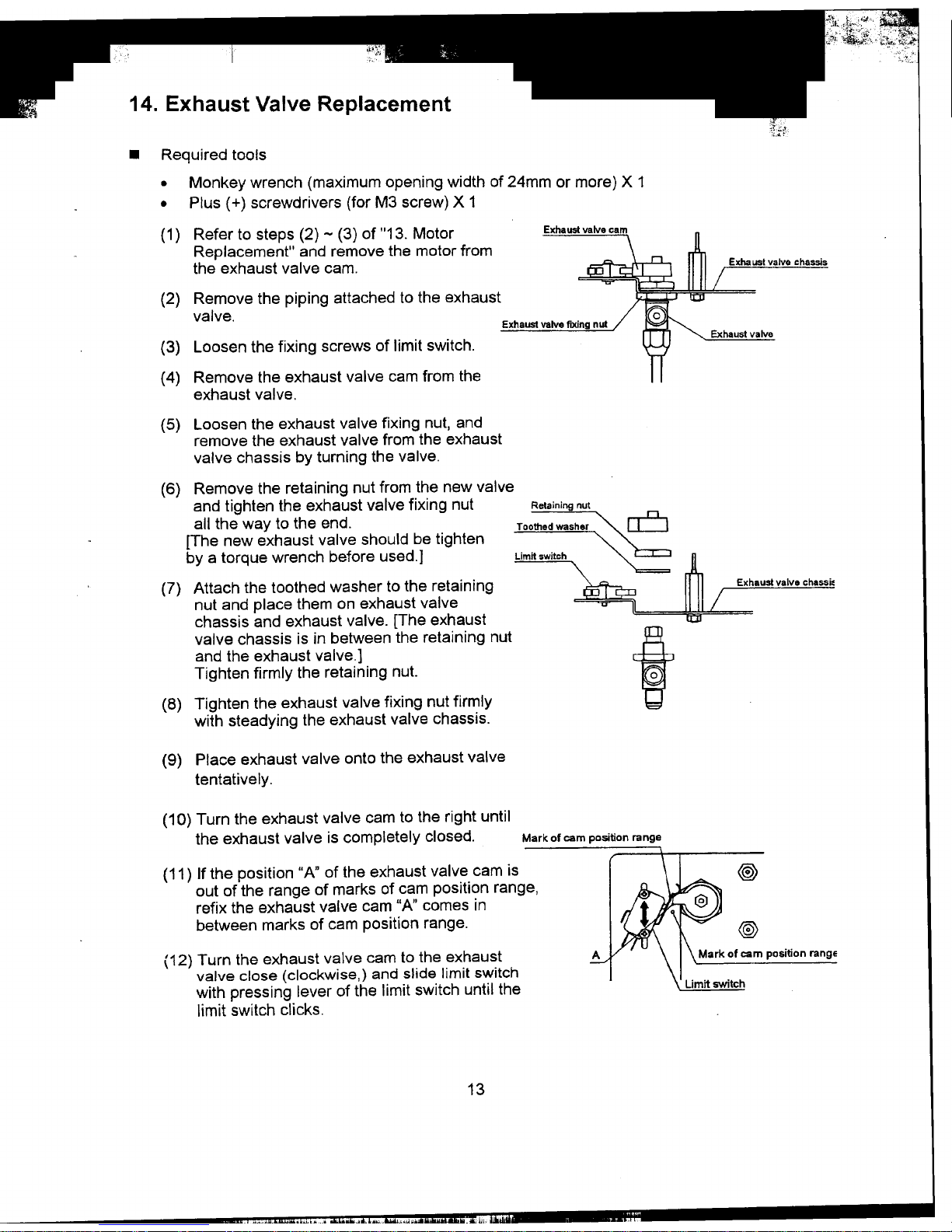
14. Exhaust Valve Replacement
.Required tools
.Monkey wrench (maximum opening width of 24mm or more) X 1
.Plus (+) screwdrivers (for M3 screw) X 1
(1) Refer to steps (2) -(3) of "13. Motor Exhaust
Replacement" and remove the motor from
the exhaust valve cam. Exhauslvalvechassis
(2) Remove the piping attached to the exhaust
valve. ExhaustvalveflJ(ingnul
(3) Lth f.. fI.. t. h Exhaustvalveoosen e Ixlng screws 0 Iml SWltc .
(4) Remove the exhaust valve cam from the
exhaust valve.
(5) Loosen the exhaust valve fixing nut, and
remove the exhaust valve from the exhaust
valve chassis by turning the valve.
(6) Remove the retaining nut from the new valve
and tighten the exhaust valve fixing nut Retainingnul
all the way to the end. TQQ
:~:~::~~;~:::::~:~~:;~:)edwaSher~
[The new exhaust valve should be tighten
by a torque wrench before used.] ::::~-""~~:~~" """""~~~~-~.L=:""-",,..-imitSWitCh
(7) Attach the toothed washer to the retaining Exhaustvalv8chass~
nut and place them on exhaust valve
chassis and exhaust valve. [The exhaust
valve chassis is in between the retaining nut tand the exhaust valve.]
Tighten firmly the retaining nut. 0
(8) Tighten the exhaust valve fixing nut firmly
with steadying the exhaust valve chassis.
(9) Place exhaust valve onto the exhaust valve
tentative Iy.
(10) Turn the exhaust valve cam to the right until
the exhaust valve is completely closed. Markofcampositionrange
(11) If the position "A" of the exhaust valve cam is @)
out of the range of marks of cam position range,
refix the exhaust valve cam "A" comes in
between marks of cam position range. @>
(12) Turn the exhaust valve cam to the exhaust Markofcampositionrange
valve close (clockwise,) and slide limit switch
with pressing lever of the limit switch until the 'tch
limit switch clicks.
13
" ",.", ,,:," .,. "C" w.

~:,~t~~7'::;;
(13) Refer to steps (4) -(6) of "13, Motor
Replacement" and fix the motor,
(14) Start operating with the normal procedure and make sure that steam does not come
out from the exhaust valve hose port while the chamber is pressurized. If steam
comes out too much, adjust the exhaust valve with reference to "16. Exhaust Valve
Adjustment. "
15. Display Board Replacement
.Required tools
.Plus ( + ) screwdrivers 2 (1 each for M5 and M3 screws)
.Vinyl adhesive tape
.Sealing tape (glass cloth impregnated with P.T.F.E.)
(1) Disconnect the connector from CN 1 ~on the control PCB.
Bind the connector and the ribbon cable ...
together with vinyl adhesive tape so as
to facilitate passing through the duct hesive tape
(2) Open the lid and unscrew the lid bottom cover fixing screws.
(3) Peel the seals covering the holes for the lid cover fixing screws and unscrew them.
Ud cover fi
Ud bottom cover fixing screw (8)
uct
(4) Pass the ribbon cable of the display board through the duct and remove the lid cover,
(5) Peel the sealing tapes (PTFE impregnated glass cloth) of the protective plastic cover,
and remove the cover by unhooking from tapping screws.
Sealing tape Protective cover Tapping screw head
~~~~~~~~~; /
! --
0 !
;: I
I! I
0 0 0
I! I I
o! i;
fJfJlIlIlIlIlIlIlIlI!fllll/Jfllllllllllllllllll~ i
14
" .oj , ~
Other manuals for HV-25
1
This manual suits for next models
3
Table of contents


