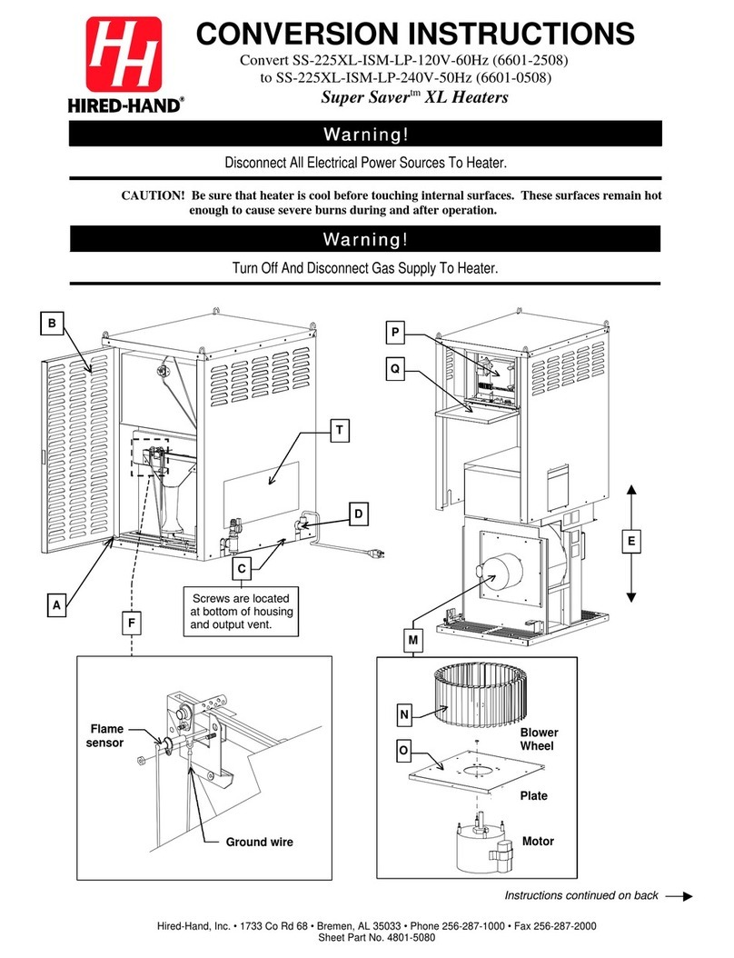
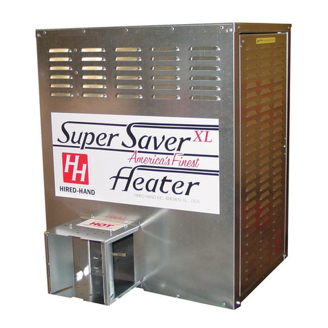
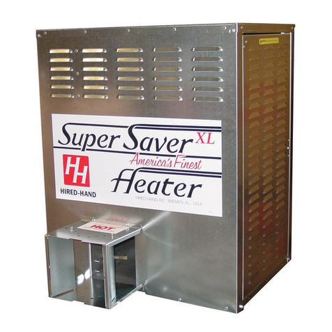
HIRED-HAND SUPER-SAVER XL SS-225-XL-120 User manual

HIRED-HAND, INC. •1733 County Road 68 •Bremen, AL 35033 USA•Phone 256-287-1000 •Fax 256-287-2000
Manual Part No. 4801-3031 Rev 6-09
FOR YOUR SAFETY
If you smell gas:
1. Open windows
2. Don’t touch electrical switches
3. Extinguish any open flames
4. Immediately call your gas supplier
CONSIGNES DE SECURITE
Si vous sentez une odeur de gaz:
1. Ouvrez les fenetres
2. Ne touchez pas aux interrupteurs electriques
3. Etegnex toute flamme hue
4. Contactez immediatement votre compangie
de gaz
FOR YOUR SAFETY
Do not store or use gasoline or any
flammable vapors and liquids in the
vicinity of this or any other appliance
CONSIGNES DE SECURITE
II es interdit d′utiliser des liquides
inflammables ou degageant des
vapeurs inflammables, a proximite
de tout appareil fonctionnant au gaz
Agricultural Building Heater
–
Direct Spark Igniter
Retain Instructions For Future Reference
MODEL BTUH kW
SS-225-XL-120 225,000 65.9
♦
Direct Spark Ignition
♦
Wash Down Design
SUPER-SAVER XLTMHEATER
Owner’s Manua
l

Part No. 4801-3031 Rev.6-09 Page 2of 22 Super Saver XL-120 Heater
GENERAL HAZARD WARNING
Failure to comply with precautions and instructions provided with this
heater can result in death, serious bodily injury and property loss or
damage from hazards of fire, explosion, burn, asphyxiation, carbon
monoxide poisoning, and/or electrical shock. If you need assistance or
heater information such as an instruction manual, labels, etc. contact the
manufacturer.
WARNING
Keep solid combustibles, such as building materials, paper or
cardboard, feathers, and dust a safe distance away from the heater as
recommended by the instructions. Never use the heater in spaces which
contain or may contain volatile airborne combustibles, or products such
as gasoline, solvents, paint thinner, dust particles, or unknown
chemicals. Failure to follow these instructions may result in a fire or
explosion, property damage, personal injury or loss of life.
WARNING
Not for home or recreational vehicle use. Installation of this heater in a
home or recreational vehicle may result in a fire or explosion, property
damage, personal injury or loss of life.
WARNING
Proper gas supply pressure must be provided to the inlet of the appliance.
Refer to rating plate for proper gas supply pressure, gas pressure in
excess of the maximum inlet pressure specified at the appliance inlet can
cause fires or explosions, leading to the serious injury, death, building
damage or loss of livestock.
USE OF EQUIPMENT
The intended use of this appliance is the heating of agricultural animal
confinement buildings.
ELECTRICAL
The electrical connections and grounding of the appliance shall be in
compliance with the National Electrical Code ANSI/NFPA 70.
!
!
!
!

Part No. 4801-3031 Rev.6-09 Page 3of 22 Super Saver XL-120 Heater
HEATER DIMENSIONS
WEIGHT 130 lb. (60 kg)
HEIGHT 30 in. (76.2 cm)
WIDTH 24-1/2 in. (62.2 cm)
DEPTH 19-1/4 in. (48.9 cm)
Table Of Contents
1. Specifications And Requirements..................4
2. Warnings And Cautions.................................5
3. Maintenance And Warranty...........................6
4. Installation......................................................7
5. User Instructions............................................8
6. Outside Mount (Optional)...............................9
7. Component And Wiring Diagram.................10
8. Ladder Type Schematic Diagram................11
9. Servicing Instructions...................................12
10. Pipe Sizing Guidelines.................................17
11. Parts & Assemblies......................................19
MINIMUM CLEARANCES
Heater must be located a minimum of 12 inches (305 mm) from ceiling, a minimum of 12 inches (305 mm) from wall,
a minimum of 20 inches (305 mm) from ground, and positioned so that livestock are unable to come in contact with
heater or within 10 feet (3 meters) of hot air discharge. (See Figure 1 - Installation Instructions).
1. Specifications And Requirements
Be Sure To Check Delivery!
Locate packing slip and make sure
all of the listed parts are enclosed.
If not, call your Hired-Hand
Distributor immediately.
Adjustable Wrench Gas Leak Testing Solution
Pipe Glue 1/4″(7 mm)
Nut Driver
Install screw hooks with hammer or drill.
Model No. Maximum Input Ventilation
(air required to support combustion)
SS-225-XL 225,000 BTUH (65.9 kW) 1000 CFM (1699 m3/hr)
LP/Propane
Gas Maximum 14 in. W.C. (34.8 mbar) and minimum 12.5 in. W.C. (31.1 mbar) inlet gas supply
pressure acceptable at gas regulator connection. Burner manifold pressure 11 in. W. C. (27.4
mbar) at maximum input. Gas pressure should be checked by a certified gas technician while
heater is in operation.
Natural
Gas Maximum 14 in. W.C. (34.8 mbar) and minimum 5 in. W.C. (12.5 mbar) inlet gas supply pressure
acceptable at gas regulator connection. Burner manifold pressure of 3.5 in. W. C. (8.7 mbar) at
maximum input. Gas pressure should be checked by a certified gas technician while heater is in
operation.
Refer to heater ratings plate for unit voltage, amperage, and frequency ratings.

Part No. 4801-3031 Rev.6-09 Page 4of 22 Super Saver XL-120 Heater
2. Warnings and Cautions
CAUTION!
1. Installation must comply with all local, state, and national codes. In the absence of Local codes,
in accordance with CAN1-B149.1 or .2. Installation Codes (Canada).
2. Follow safety, maintenance, and test firing instructions packaged with Heater.
3. Refer to model specifications label for gas type (LP or Natural Gas).
4. Check all connections for gas leaks.
5. Gas supply and regulator must be installed outside building.
6. The hose assembly should be protected from traffic, building materials, and any contact with hot
surfaces both during use and while in storage.
7. Do not open doors, or move or handle heater while hot, burning, or connected to power supply.
8. Turn power off before servicing. (Heater may start at any time if power is connected).
9. Heater is not recommended for heating human living quarters.
10. Not to be used for heating where flammable liquids and vapors are stored or used.
11. Inadequate gas volume and (or) pressure will directly influence the combustion efficiency of the
heater. Adequate gas volume and (or) pressure is the responsibility of the installer.
12. Adequate ventilation must be provided.
13. Combustion and ventilation air must not be obstructed.
14. Not for use with duct work other than types provided by manufacturer.
15. Position heater properly before use. Heater must be level and in accordance with minimum
clearances.
16. For safety, this heater is equipped with air flow proving switch and manual-reset high limit switch.
17. Keep temperature of fuel containers below 100° F (37.8°C). Containers must be installed
outside building.
18. Heater must not be operated for one hour following wash-down.
WARNING
When Heater Is Connected To Remote Thermostat
Heater May Start At Any Time!
!
ELECTRICAL GROUNDING INSTRUCTIONS
This appliance requires a three prong (grounding) plug
for your protection against electrical shock and should be plugged
directly into a properly grounded three-prong receptacle.

Part No. 4801-3031 Rev.6-09 Page 5of 22 Super Saver XL-120 Heater
3. Maintenance and Warranty
MAINTENANCE
1. The appliance area should be kept clear & free from combustible materials, gasoline and other
flammable vapors, and liquids.
2 The flow of combustion and ventilation air must not be obstructed.
3. Your Super Saver XL Heater should be inspected before each use, and at least annually by a qualified
service person.
4. The hose should be visually inspected prior to each use of the heater. If it is evident there is excessive
abrasion or wear or the hose is cut, it must be replaced prior to the heater being put into operation.
The replacement hose assembly shall be that specified by the manufacturer. (See parts list).
5. Inspect heater and gas connections periodically for gas leaks with an approved gas leak testing
solution (soap and water work well).
6. Keep heater clean at all times.
A. Open doors and blow out dust with high pressure air hose. Be sure interior of burner
and flared end are kept clean.
B. Burner orifice and direct spark ignition assembly must be kept clean and free of
carbon build-up.
C. Check blower wheel regularly for dust accumulation and clean periodically for
maximum airflow.
D. Thermostat coils must be kept clean to assure proper temperature control.
E. Heater must be cool before wash down. Do not operate heater for one hour following
wash-down.
DISCLAIMER
This appliance rating is based on the use of ANSI LC-2 test gases including LP (2500 BTU/ft3,
93.15 MJ/m3) and natural gas (1075 BTU/ft3, 40 MJ/m3). Hired-Hand, Inc. makes no guarantees
regarding the proper operation of this appliance when these conditions are not met.

Part No. 4801-3031 Rev.6-09 Page 6of 22 Super Saver XL-120 Heater
Limited Warranty
4. Warranty
The GSI Group, LLC. (“GSI”) warrants products which it manufactures to be free of defects in
materials and workmanship under normal usage and conditions for a period of 12 months after
sale to the original end-user or if a foreign sale, 14 months from arrival at port of discharge,
whichever is earlier. The end-user’s sole remedy (and GSI’s only obligation) is to repair or
replace, at GSI’s option and expense, products that in GSI’s judgment, contain a material defect in
materials or workmanship. Expenses incurred by or on behalf of the end-user without prior
written authorization from the GSI Warranty Group shall be the sole responsibility of the end-user.
Warranty Extensions: The Limited Warranty period is extended for the following products:
Product Warranty Period
Performer Series Direct Drive
Fan Motor 3 Years
All Fiberglass Housings Lifetime
AP Fans and
Flooring All Fiberglass Propellers Lifetime
Feeder System Pan Assemblies 5 Years **
Feed Tubes (1.75" & 2.00") 10 Years *
Centerless Augers 10 Years *
Cumberland
Feeding/Watering
Systems Watering Nipples 10 Years *
Grain Systems Grain Bin Structural Design 5 Years
Portable & Tower Dryers 2 Years
Grain Systems
Farm Fans
Zimmerman Portable & Tower Dryer Frames
and Internal Infrastructure † 5 Years
GSI further warrants that the frame, basket and excluding all auger and auger drive components of the portable and tower
dyer shall be free from defects in materials for a period of time beginning on the twelfth (12th) month from the date of
purchase and continuing until the sixtieth (60th) month from the date of purchase (extended warranty period). During the
extended warranty period, GSI will replace the frame or basket components that prove to be defective under normal
conditions of use without charge, excluding the labor, transportation, and/or shipping costs incurred in the performance of
this extended warranty.
Conditions and Limitations:
THERE ARE NO WARRANTIES THAT EXTEND BEYOND THE LIMITED WARRANTY DESCRIPTION SET FORTH
ABOVE. SPECIFICALLY, GSI MAKES NO FURTHER WARRANTY OF ANY KIND, EXPRESS OR IMPLIED,
INCLUDING, WITHOUT LIMITATION, WARRANTIES OF MERCHANTABILITY OR FITNESS FOR A PARTICULAR
PURPOSE OR USE IN CONNECTION WITH: (i) PRODUCT MANUFACTURED OR SOLD BY GSI OR (ii) ANY
ADVICE, INSTRUCTION, RECOMMENDATION OR SUGGESTION PROVIDED BY AN AGENT, REPRESENTATIVE
OR EMPLOYEE OF GSI REGARDING OR RELATED TO THE CONFIGURATION, INSTALLATION, LAYOUT,
SUITABILITY FOR A PARTICULAR PURPOSE, OR DESIGN OF SUCH PRODUCTS.
GSI shall not be liable for any direct, indirect, incidental or consequential damages, including, without limitation,
loss of anticipated profits or benefits. The sole and exclusive remedy is set forth in the Limited Warranty, which
shall not exceed the amount paid for the product purchased. This warranty is not transferable and applies only to
the original end-user. GSI shall have no obligation or responsibility for any representations or warranties made
by or on behalf of any dealer, agent or distributor.
GSI assumes no responsibility for claims resulting from construction defects or unauthorized modifications to
products which it manufactured. Modifications to products not specifically delineated in the manual
accompanying the equipment at initial sale will void the Limited Warranty.
This Limited Warranty shall not extend to products or parts which have been damaged by negligent use, misuse,
alteration, accident or which have been improperly/inadequately maintained. This Limited Warranty extends
solely to products manufactured by GSI.
Prior to installation, the end-user has the responsibility to comply with federal, state and local codes which apply to the location and
installation of products manufactured or sold by GSI.
* Warranty prorated from list price:
0 to 3 years – no cost to end-user
3 to 5 years – end-user pays 25%
5 to 7 years – end-user pays 50%
7 to 10 years – end user pays 75%
** Warranty prorated from list price:
0 to 3 years – no cost to end-user
3 to 5 years – end-user pays 50%
† Motors, burner components and
moving parts not included. Portable
Dryer screens included. Tower Dryer
screens not included.

Part No. 4801-3031 Rev.6-09 Page 7of 22 Super Saver XL-120 Heater
5. Installation
5.1 Hanging The Heater
Chain Suspension Cable Suspension
Mount heater with screw hooks and chains so that
back of heater is at least 12 inches (305 mm) from
ceiling and wall. Heater must be a minimum of 20
inches (500 mm) from floor, and located so livestock
and combustible materials are unable to come in
contact with heater or within 10 ft (3 meters) of hot air
discharge.
If frequent height adjustment is required, use
cables and pulleys. Main line cable would be
connected to a winch.
5.2 Directions For Leveling
Adjust cables or chains as required
to level the heater. Use a
carpenter's level to check that the
heater is level.
5.3 Installing Dual-Flare Duct
Fold Dual-Flare duct to shape as
shown in Fig. 1. Install Dual-Flare
duct to heater exhaust (Fig. 1) as
shown with sheet metal screws
provided. This provides a multi-
directional heat flow that may be set
by bending flaps.
5.4 Connecting the Gas Supply
For gas connection (Fig. 2) attach
regulator to the Hi-Pressure Line (A)
at outside of building. Connect
flexible hose (B) to low pressure end
of regulator with special brass
coupling. See page 1 for LP, and
natural gas requirements.
Fig. 2
A
B
High Pressure
Line
Gas Regulato
r
Flexible
hose
Fig. 2
Attach Flare
Duct To
Heater With
Sheet Metal
Screws
Adjust Flap To
Direct Heat Flow
Flare Duct
Fig. 1

Part No. 4801-3031 Rev.6-09 Page 8of 22 Super Saver XL-120 Heater
6. User Instructions
Before turning on gas, check main supply valve to be sure it is open (Fig. 3). Be sure to check all
connections for leaks with a Gas Leak Testing solution, (soap and water work well). Check to see if gas
valve knob is in the ON position. If not, turn counter-clockwise until knob “clicks” into the ON position.
(This may not apply to all units). Turn on gas by turning ball valve handle into vertical position.
6.1 Connecting Electrical Power
Make sure a circuit breaker or similar cutoff device is provided to permit disconnection of
electrical power to heater for service and cleaning. This heater is designed to be wired directly,
with no plugs and outlets necessary. All electrical work should be performed by a certified electrician.
The wiring diagrams on pages 7-8 show how to wire a line power supply directly to the heater’s
terminal block. If no adjustments are made, the heater will operate every time power is supplied and
the on/off switch is activated. If an external thermostat is to be used (See Component & Wiring
Diagram), the heater will operate only when power is supplied, the on/off switch is activated, and the
thermostat indicates a call for heat.
6.2 Starting Up
Adjust thermostat higher than house
temperature. Allow 20 seconds for
heater to ignite. On initial start up or
when heater has not been in service
for some time, heater may require
more than one attempt to purge air
and ignite heater. (IF HEATER
FAILS TO IGNITE. REFER TO
TROUBLE SHOOTING GUIDE).
Adjust thermostat to desired house
temperature.
6.3 Shutting OFF Heater
Shut off main gas supply valve, close
ball valve, and disconnect electrical
power.
CAUTION!
LIMITING EXCESS CARBON DIOXIDE (CO2 )
In order to prevent hazardous accumulation of CO2 gases, the heater must
operate ONLY in a properly ventilated room.
Ventilation requirements are given in 'Specifications and Requirements' on page 1.
Both installer and operator must ensure that the building’s ventilation rate never drops
below the noted limits.
To Heater
To Gas
Supply
Gas Ball Valve
Shown in
"ON" Position
Fig. 3

Part No. 4801-3031 Rev.6-09 Page 9of 22 Super Saver XL-120 Heater
7. Outside Mount (Optional)
Hired-Hand heaters are available in Outside Mount (OSM) models. These heaters are designed to be mounted to
the outside wall of a building. This saves valuable space inside the building and ensures fresh air intake for the
heater. If you have purchased one of our OSM heaters, please read the following before installing your new heater.
1. Before disposing of the box, cut the installation template
from the side.
2. Position template on outside of building where heater is
to be mounted. Be sure the template is level.
3. Drill 6.3 mm (1/4″) holes through all 8 X’s shown on
template. NOTE: Opening for duct measures 254 mm
(10″) width (W) x 254mm (10″) height (H). See Detail A.
4. Locate 4 X’s for thru-wall extension duct and cut from
one hole to the next until opening is removed. See Detail
A.
5. If additional support is needed, add support by fastening
two 2' x 4' boards on outside of wall where heater
support brackets are to be positioned. The two 2' x 4'
boards are to be fastened to studs inside the wall. See
Detail B.
6. Assemble heater support bracket as shown in Detail C.
7. Insert thru-wall extension duct assembly through
opening in wall. The ‘varmint’ flap, located inside the
thru-wall extension duct, should be positioned as shown
in Detail D.
8. Bend extension duct mounting flange into a rectangle
and fasten around exhaust outlet on front of heater with
sheet metal screws provided.
9. Place heater on support bracket. Support bracket must
be level before heater is set in place.
10. Slide thru-wall extension duct assembly into
mounting flange, and secure with sheet metal
screws.
11. Place outer flashing seal around thru-wall extension
duct and secure with sheet metal screws to inside
of wall.
12. Fasten directional duct to extension duct mounting
flange, then bend deflectors until they force heated
air in the desired direction.
13. To continue with installation of your heater, see
‘User Instructions’ section on the next page.
CAUTION!
The minimum side clearance to combustible walls must be 305 mm (12 inches).
The minimum clearance between the appliance and rear wall must be 305 mm (12 inches).
Weeds, snow, or other materials must not be allowed to accumulate on heater or adjacent to heater. Heater and
thru-wall extension duct must be a minimum of 500 mm (20 inches) above ground and out of reach of livestock.
Detail C
1
2
3
4
5
6
7
8
9
10
11
12
13
Detail D
Detail B
Detail A
H
W
W = 254 mm (10
″
)
H = 254 mm (10″)
Legend
1. Wall (By others)
2. Rain shield, included with OSM heater.
3. Door, included with OSM heater.
4. Mounting brace, included with OSM kit.
5. Gas shutoff valve, included with heater.
6. Thru-wall extension duct, included with OSM kit.
7. Dual flare duct. Use T-duct included with heater
or use optional OSM Y-duct ordered separately.
8. Extension flange, included with OSM kit.
9. Gas hose, optional ordered separately.
10. 2 x 4 Framing for Brace, not included
11. ‘Varmint’ flap, included with OSM kit.
12. Inner flashing seal, included with OSM kit.
13. Outer flashing, included with OSM kit.

Part No. 4801-3031 Rev.6-09 Page 10 of 22 Super Saver XL-120 Heater
CONTROL BOX
8
7
THERMOSTAT OPTIONS
Low Voltage Control
Direct Wire Thermostat
or Controller Piggy-Back
Thermostat
INSIDE HEATER
REMOVE JUMPER
FOR DIRECT WIRE
THERMOSTAT OPTION
8. Component and Wiring Diagram
COMPONENT AND WIRING DIAGRAM
120 Volts A.C. 50/60 Hz Single Phase

Part No. 4801-3031 Rev.6-09 Page 11 of 22 Super Saver XL-120 Heater
SPARK
IGNITER
BLACK
WHITE
HOT NEUTRAL
GROUND
LINE VOLTAGE
THERMOSTAT
10 AMP FUSE
ON / OFF
TRANSFORMER
24 VAC-40VA, 50/60 Hz
LINE VOLTAGE
LOW LINE
UNITED TECHNOLOGIES
Direct Spark Ignition Control
FLAME SENSOR
PROBE
GND
REDUNDANT
VALVE
MAIN
VALVE
HIGH LIMIT
SWITCH
SAIL SWITCH
IND
L1
COM
R
PS1
X
PS2
W
MV
C
FS
MOT
HV
GND
9. Ladder Type Schematic Diagram
LADDER TYPE SCHEMATIC DIAGRAM

Part No. 4801-3031 Rev.6-09 Page 12 of 22 Super Saver XL-120 Heater
10. Servicing Instructions
10.1 United Technologies Direct Spark Ignition System
IMPORTANT!
Inspect and check operation of this appliance monthly. Follow the
instructions below. If a problem is detected, contact a qualified
technician to make any necessary repairs.
In an effort to minimize the time required to trouble shoot this system:
1. Turn off the gas supply at the main gas valve.
2. Disconnect electric power to system at main fuse of circuit breaker, if connected.
3. Visually inspect equipment for apparent damage. Check wiring for loose
connections.
4. Inspect igniter for visible cracking or scale deposits. Inspect flame sensor for
position or deposits shorting sensor to burner.
5. After performing the above inspections, restore gas supply, and electric power to the
equipment. Close thermostat contacts to cycle the system. If a “no heat” condition
persists, the three visual indicators listed below will help determine if system is
operating properly.
The igniter will spark.
The main burner flame will ignite.
The main burner flame will continue to burn after the igniter is
turned off.
Trouble shooting the system consists of checking for these three visual indications.
The Visual Check Charts define the proper action if any of these indications do not
occur.
1
2
3
120 Volts A.C. 50/60 Hz Single Phase

Part No. 4801-3031 Rev.6-09 Page 13 of 22 Super Saver XL-120 Heater
10.2 1016 Direct Spark Ignition
Status Indicator Error Conditions
The status indicator LED will not be lit with power applied to the board and the control operating
properly. However, if the control is not operating properly, the status indicator LED will flash in
one of the following error codes.
1. Status Indicator Flashing One Time
When the status indicator LED shows the error code of a single repeated flash, the control is
in lock-out, because the sail switch was stuck closed.
2. Status Indicator Flashing Two Times
When the status indicator LED shows the repeating error code of two flashes, the control is in
lock-out because the control circuits did not receive the “closed” signal from the high limit
switch, the sail switch, and the low gas pressure switch*within the required amount of time.
3. Status Indicator Flashing Three Times
When the status indicator LED shows the repeating error code of three flashes, the control is
in lock-out due to failed ignition attempt.
4. Status Indicator Flashing Four Times
When the status indicator LED shows the repeating error code of four flashes, the control has
gone into lock-out due to a failure within the control board.
10.3 Checking Manifold Pressure
To be performed by a certified gas technician only!
1. Unplug heater from power source and turn ball valve to OFF position.
2. Remove outlet pressure tap plug from gas control valve and connect pressure gauge.
3. Return electrical power to heater and plug to power source and turn ball valve to ON
position.
4. To obtain an accurate manifold pressure reading, heater must be cycled on and off
several times to stabilize the pressure regulator diaphragm.
5. Return the heater to operation and read pressure gauge.
6. If necessary, adjust pressure regulator on gas control valve to the acceptable manifold
pressure found on rating plate and page 1 of owner’s manual.
7. Remove pressure regulator adjustment screw.
8. Using a screwdriver, turn inner adjustment screw clockwise to increase or counter
clockwise to decrease manifold pressure to burner.
9. Always replace cap screw and tighten firmly to prevent gas leakage.
10. Unplug heater from power source and turn ball valve to OFF position.
11. Remove pressure gauge and replace outlet pressure tap plug.
12. Return heater to operation and observe through at least one complete cycle to ensure all
controls are operating properly.
13. Perform gas leak test at outlet pressure tap plug. (Soap and water work well).

Part No. 4801-3031 Rev.6-09 Page 14 of 22 Super Saver XL-120 Heater
Does igniter
spark ?
Is 24V present
across module
terminals
X and COM ?
Is 24V
present
across module
terminals
Ps1 and PS2 ?
Is line voltage
present across module
terminals L1 and C ?
Does igniter have
carbon or dust
build-up?
Remove igniter.
Clean igniter with fine
steel wool or emery
cloth. Spark gap
should be 1/8”.
Reinstall igniter.
Disconnect igniter wire.
Connect ohm meter to igniter
wire terminals. Is resistance
greater that 100 ohms?
Replace igniter wire Replace 1016
United Technologies
control.
10.4 Chart 1 First Visual Check
Chart 1
First Visual Check

Part No. 4801-3031 Rev.6-09 Page 15 of 22 Super Saver XL-120 Heater
M
10.5 Chart 2 Second Visual Check
Chart 2
Second Visual Check
NOTE: All voltage readings 10% - 15%

Part No. 4801-3031 Rev.6-09 Page 16 of 22 Super Saver XL-120 Heater
Igniter remains
sparking with main
burner flame
present.
Replace 1016
United
Technologies
Control
Replace 1016
United
Technologies
Control.
Is control
box C
terminal wired
to burner ground ?
DSI system cycle
complete.
10.6 Chart 3 Third Visual Check
Chart 3
Third Visual Check

Part No. 4801-3031 Rev.6-09 Page 17 of 22 Super Saver XL-120 Heater
b
Gate
valve
Arbitrary Piping System
ac
d
e
f
g
Heaters
Heaters
30
m
8
m
Gas meter 8
m
tees
11. Pipe Sizing Guidelines
11.1 Calculating HVR & ELOP
1. Using a system schematic, label each piping
section of the system starting at the meter or
regulator. A different pipe section starts
where the gas demand of the system
changes, usually at a junction.
2. Determine the Heating Value Required
(HVR) in BTUH (BTU's per hour) for each
section of pipe.
HVR = (no. heaters supplied by pipe
section) X (heat output per heater)
3. Determine the Equivalent Length Of Pipe (ELOP)
required for sufficient gas service.
ELOP = (length from meter to most remote heater)
+ (Minor loss equivalents of the system)
IMPORTANT: Use the ELOP value from this
equation for size determination of all pipe sections.
4. Use the ELOP value from step 3, and the HVR of
each pipe section to determine the required pipe size
for either natural gas (NG) (Table 1) or liquid propane
(LP) (Table 2) from the table 'Maximum Capacity Of
Pipe'.
11.2 Directions for Reading Pipe Size From Tables:
EXAMPLE: Four 40,000 BTUH (12 kW) heaters will be installed on the gas pipe line in the 'Arbitrary Piping System'
diagram below. NOTE: Values given in English and Metric equivalent units.
1. Determine the HVR value for each pipe section of the system.
Pipe Section No. Of Heaters HVR Calculation HVR Value
BTUH kW BTUH kW
a-b 4 4 x 40,000 4 x 12 160,000 48
b-c 2 2 x 40,000 2 x 12 80,000 24
c-e 1 1 x 40,000 1 x 12 40,000 12
b-d 1 1 x 40,000 1 x 12 40,000 12
b-f 1 1 x 40,000 1 x 12 40,000 12
c-g 1 1 x 40,000 1 x 12 40,000 12
2. Determine the ELOP. Length from meter to most remote heater = length from a to e (or g) = 100ft (30m) + 25ft
(8 m) = 125ft (38 m) Minor loss equivalents from Table 1 = 1 gate valve x 2ft/valve (1 m/valve) + 3 tees x 11
ft/tee (4 m/tee) =35ft (13 m). Calculated ELOP = 125ft (38 m) + 35ft (13 m) = 160 ft (51 m) Tabulated ELOP =
200ft (60 m) Round up to the nearest table value.
3. In the appropriate table, NG (Table 2) or LP (Table 3), select the column showing the ELOP or the next longer
length, if the table does not give the exact length. Use this column to compare table values to the HVR values.
Use the Natural Gas table (Table 2) in this example. From step 2,
ELOP = 200ft (60 m) Locate the column labeled 200ft
(60 m) in Table 2.
4. Select a pipe section and read down the ELOP column to
find the maximum gas capacity that matches the HVR for
that particular pipe section. If the exact value is not
listed, choose the next larger value in the column. In this
example, start with pipe section c-e. For pipe section c-
e, HVR = 40,000 BTUH (12 kW). From Table 2, column
200 ft, 40 (12) is not listed (NOTE: The table values are
in thousands of BTUH's). The next larger value of 72
(21) is read from the table, corresponding to 72,000
BTUH (21 kW).
5. Follow the row leftward until you reach the columns
labeled 'Internal Diameter' and 'Nominal pipe size'. Read
the pipe size for the particular pipe section. For
example, for pipe section c-e, the pipe size is ¾ inch
(0.824 in.) (19.1 mm). Repeat for each pipe section.

Part No. 4801-3031 Rev.6-09 Page 18 of 22 Super Saver XL-120 Heater
Table 1
Minor Loss Equivalents
Fitting 2" (5.08 cm) IPS Or Smaller 2” (5.08 cm) IPS To 4” (10.16 cm) IPS
Feet per fitting Meters per fitting Feet per fitting Meters per fitting
45°Elbow 3 1 5 2
90°Elbow 6 2 10 3
Tee 11 4 20 6
Gate Valve 2 1 3 1
Angle Valve 29 9 60 18
Swing Valve 15 5 30 9
Table 2. Maximum Capacity Of Pipe In Thousands Of BTU per Hour
Nominal Internal Natural Gas (Methane) @ Pressure Drop Of 0.5 in w.c. (0.2 mbar)
Iron Pipe Diameter, Values listed are for 0.6 sp.gr. based on Heat Of Combustion of 1000 BTU/cu .ft
Size, (IPS) Length Of Pipe, Feet (multiply ft by 0.3 to convert to meter)
Inch* Inch* 10 20 30 40 50 60 70 80 90 100 150 200 250 300
1/2 .622 175 120 97 82 73 66 61 57 53 50 40 35 29 25
3/4 .824 360 250 200 170 151 138 125 118 110 103 84 72 59 53
1 1.049 680 465 375 320 285 260 240 220 205 195 160 135 109 100
1-1/4 1.380 1400 950 770 660 580 530 490 460 430 400 325 280 219 206
1-1/2 1.610 2100 1460 1180 990 900 810 750 690 650 620 500 430 325 309
2 2.067 3950 2750 2200 1900 1680 1520 1400 1300 1220 1150 950 800 614 596
2-1/2 2.469 6300 4350 3520 3000 2650 2400 2250 2050 1950 1850 1500 1280 966 950
3 3.068 11000 7700 6250 5300 4750 4300 3900 3700 3450 3250 2650 2280 1855 1680
4 4.026 23000 15800 12800 10900 9700 8800 8100 7500 7200 6700 5500 4600 3783 3432
Table values given in BTUH/1000. To convert to kW, multiply table values by 0.3
* 1 inch = 25.4 mm
Pipe Sizes Determined For Diagram
Pipe Section Max Gas Capacity Value Determined From Table 2 Pipe Size Determined From Table 2
BTUH kWh inches mm
a-b 280,000 82 1-1/4 in 31.8
b-c 135,000 40 1 in 25.4
b-d 72,000 21 ¾ in 19.1
b-f 72,000 21 ¾ in. 19.1
c-e 72,000 21 ¾ in. 19.1
c-g 72,000 21 ¾ in . 19.1
IMPORTANT
Tables 2 and 3 are based on values given in the Gas Engineers Handbook and are intended as a guide only.
Consult your gas supplier for gas capacity and pipe size information for your particular piping system.
Table 3. Maximum Capacity Of Pipe In Thousands Of BTU per Hour
Nominal Internal Liquid Propane (LP) @ Pressure Drop Of 0.5 in w.c.
Iron Pipe Diameter Values listed are for 1.6 sp.gr. based on Heat Of Combustion of 2500 BTU/cu .ft
Size, (IPS) Length Of Pipe, Feet (multiply ft by 0.3 to convert to meter)
Inch* Inch*
10 20 30 40 50 60 80 100 125 150 200 250 300 350 400
1/2 .622 291 200 161 137 122 110 94 84 74 67 58 51 46 43 40
3/4 .824 608 418 336 287 255 231 198 175 155 141 120 107 97 89 83
1 1.049 1146 788 632 541 480 435 372 330 292 265 227 201 182 167 156
1-1/4 1.380 2353 1617 1299 1111 985 892 764 677 600 544 465 412 374 344 320
1-1/2 1.610 3525 2423 1946 1665 1476 1337 1144 1014 899 815 697 618 560 515 479
2 2.067 6789 4666 3747 3207 2842 2575 2204 1954 1731 1569 1343 1190 1078 992 923
Table values given in BTUH/1000. To convert to kW, multiply table values by 0.3.
* 1 inch = 25.4 mm

Part No. 4801-3031 Rev.6-09 Page 19 of 22 Super Saver XL-120 Heater
When ordering service parts, please specify the country, model number, date of manufacture, voltage, frequency,
gas type, inside or outside mount, and whether the heater is constructed of galvanized or stainless steel.
1045-1305 Natural Gas
1045-0100 LP/Propane Gas
1021-2501
6401-4543
3005-0108 1903-3802
6401-4515
6401-4512
0404-2358
6450-0094
3005-21303005-0102
1010-1317 LP/Propane Gas
1010-2500 Natural Gas
6401-4510
12. Parts & Assemblies

Part No. 4801-3031 Rev.6-09 Page 20 of 22 Super Saver XL-120 Heater
6401-1151
-
-6401-4504
6401-4543
6401-1140
0404-6674
1004-1406
0404-6703
Model HH-SS-225
3002-6010
1041
-
1488
1009
-
1500
1021
-
1500
1021-1496
1041
-
1491
1021
-
1495
3004
-
0100 LP/Propane Gas
3004
-
0101 Natural Gas
1041
-
5004
SEE MODEL NO.
1004
-
1422
1004
-
1102
6401
-
1308
100
4
-
602
9
1001
-
2597
8089
0408
-
-
1005
0100
Table of contents
Other HIRED-HAND Heater manuals
