HIRO LIFT HIRO 320 User manual
Edition 2.08 1030010
Operating Instructions
for inclined wheelchair lifts
HIRO 320, HIRO 350, HIRO 360, HIRO 370
Straight and turning platform lift systems

1. Contents
2
1. Contents......................................................................................................................................Page 2
2. Meaning of symbols and glossary of terms.............................................................................Page 4
3. Warranty......................................................................................................................................Page 5
4. General safety instructions.......................................................................................................Page 6
5. Summary of HIRO inclined lifts
5.1 HIRO 320 — turning platform lift system............................................................................. Page 9
5.2 HIRO 350 — straight platform lift system.......................................................................... Page 10
5.3 HIRO 360 — turning lowerable platform lift system.......................................................... Page 11
5.4 HIRO 370 — turning lowerable platform lift system.......................................................... Page 12
5.5 Platform components and accessories............................................................................. Page 13
5.6 Safety devices................................................................................................................... Page 15
6. Operation of HIRO inclined lifts
6.1 Requirements for initial operation ..................................................................................... Page 17
6.2 Key-operated systems ...................................................................................................... Page 19
6.3 Calling the wheelchair lift and riding (lift with key-operated platform control and remote
control).............................................................................................................................. Page 21
6.3.1 Call platform - from downstairs ............................................................................. Page 21
6.3.2 Riding upstairs ...................................................................................................... Page 24
6.3.3 Call platform - from upstairs.................................................................................. Page 28
6.3.4 Riding downstairs.................................................................................................. Page 30
6.4 Calling the wheelchair lift and riding (lift with ON/OFF key).............................................. Page 34
6.4.1 Call platform - from downstairs ............................................................................. Page 34
6.4.2 Riding upstairs ...................................................................................................... Page 36
6.4.3 Call platform - from upstairs.................................................................................. Page 43
6.4.4 Riding downstairs.................................................................................................. Page 45
6.5 Mounting and dismounting the wheelchair lift at intermediate stops................................. Page 52
6.6 Deactivating the system.................................................................................................... Page 54
6.7 Display .............................................................................................................................. Page 55
6.8 Maintenance and cleaning instructions............................................................................. Page 56
7. Dealing with faults
7.1 Emergency operation........................................................................................................ Page 57
7.1 Moving the platform: Model with hand wheel....................................................... Page 57
7.1 Moving the platform: Model with electrically operated emergency control........... Page 59
7.2 Manually lowering the HIRO 360 and HIRO 370 platform lift system .................. Page 60
7.2 Emergency evacuation...................................................................................................... Page 61
7.3 Battery change.................................................................................................................. Page 64
7.4 Troubleshooting in case of malfunctions........................................................................... Page 65
8. Maintenance..............................................................................................................................Page 72
9. Assembly and disassembly ....................................................................................................Page 73

1. Contents
3
10. Disposal ....................................................................................................................................Page 74
11. Technical data ..........................................................................................................................Page 75
12. EC Conformity Declaration......................................................................................................Page 76
Please keep these instructions for further reference!
2. Meaning of symbols and glossary of terms
4
Key to symbols
Caution! Risk of personal injury!
Attention! Risk of material damage!
Advice
Multi-floor systems
Glossary (list of technical terms)
Platform control: Control unit in lift with key switch and command buttons.
Remote control: Battery-operated radio transmitter unit with control buttons and indicator light.
Two different models of the remote control unit are available: one with and one
without a key -switch (see Section 6.2, "Key-operated systems", on page 19).
The remote control can be fitted to the wall.
Turning: Platform lift systems are called "turning lift systems" if the travel path of the
platform has either curves to the right or to the left side.
Straight: Platform lift systems are called "straight" if the travel path of the platform has
neither curves to the right nor to the left side.
A curve in the travel path e.g. when changing from inclined to horizontal travel is
nevertheless possible.

3. Warranty
5
Warranty
For a correct use following terms apply:
• The platform lift system may only be used according to the contractual and legal provisions.
• Only one person may ride the platform lift system. It should never be used by more than one person at
a time.
• The lift system is only for conveying a person in a wheelchair. In the special version with a folding seat
it is also permissible to convey a seated person. Standing persons are not allowed to be conveyed.
• The lift is not designed for conveying goods or objects.
• The maximum load may not be exceeded.
• The platform lift system is not a toy.
The function and safety of the equipment is only guaranteed if:
• the system is correctly used and properly operated, i.e. as described in these instructions. Pay special
attention to the safety advice.
• the system is kept in a safe operational state.
• the regular maintenance works are carried out by HIRO LIFT or by a representative authorised by
HIRO LIFT.
• repairs are carried out by HIRO LIFT or by a representative authorised by HIRO LIFT.
• constructional changes, conversions or a possible reconstruction of the system are carried out by
HIRO LIFT or by a representative authorised by HIRO LIFT.
• only spare parts are used that the manufacturer has expressly designated for this system.
• the system is operated on the site stated in the contract. Any warranty is excluded if the system is
removed and built up again at a new place.
Warranty is no longer granted if manipulations or works are carried out by non-authorised persons.
Authorised persons are HIRO LIFT employees or authorised representatives of HIRO LIFT.

4. General safety instructions
6
General safety instructions
Please read these safety instructions carefully before you operate or use this platform lift system.
Please observe these safety instructions!
• Everyone who uses the wheelchair lift or turns the key to prepare the lift for operation must be familiar
with the platform lift system and have been briefed on its use.
• The operator of the system must ensure that the wheelchair lift is only used by persons who have
been briefed.
• The operator of the system is responsible for the safe and proper use of the wheelchair lift.
• The operator and all persons who use the wheelchair lift must read and understand these operating
instructions in advance.
• Persons who are not able to read or understand the operation instructions may only use the system
together with an instructed person.
• Beside the advice in these instructions pay attention to the special signs on the system.
• A second person, who is not dependent on the platform lift system, always has to be instructed in its
use. This person acts as the so-called "qualified person" in accordance with the German Health and
Safety at Work Act (Betriebssicherheitsverordnung) and must be able to assist if problems arise.
• The system should only be used if an instructed attendant is present.
• The attendant is responsible that the wheelchair with its user is placed on the platform so that
crushing or other injuries are avoided.
• If the system is operated without an attendant, the rider should carry with him a cell phone or similar.
• The wheelchair lift may only be operated via remote control if the person with the remote control unit
can see that the entire travel path is clear. If some sections of the travel path cannot be seen, mirrors
or similar aids must be installed to rectify this.
• Before operating the wheelchair lift for the first time, ensure that the remote control units are installed
at locations where the entire path of the wheelchair lift can be seen by the person operating the
remote control.
• Multi-floor systems may not be operated via a portable or stationary remote control. Exceptions: if all
parts of the travel path can be observed by technical means.
• Do not allow the system to touch metal objects (e.g. tinsel) as this may cause a short-circuit.
• In models with round tubular rails, always keep the rails dry and clean. Do not treat them with grease,
oil or other lubricants.
• In model HIRO 350Z, the toothed drive rack must be regularly lubricated with grease. Contact the
HIRO LIFT service department.
• An outdoor inclined platform lift is subject to a risk of slipping during rain.
• For outdoor inclined platform lifts, the lift itself as well as its access must be kept free from ice and
snow. Otherwise there is a risk of slipping.
• Some outdoor lift models are fitted with a rail heating system and with a safety catch heating system.
These heating systems must be switched on and be functional at all times during winter and when the
ambient temperature is below 5° C (41° F).
• When outdoor lifts are used, it must be ensured that the humidity does not exceed a value of 80
percent.
• Lift systems which are designed as indoor lifts must under no circumstances be used outdoors, i.e. in
locations where they are exposed to the weather.

4. General safety instructions
7
• When indoor lifts are used, it must be ensured that the humidity does not exceed a value of 80
percent and the ambient temperature is 5° C (41° F) or above.
• Only use wheelchairs that fit the size of the platform.
• Only use wheelchairs with footrests so that the feet do not protrude from the platform. Feet or
footrests must not be allowed to block the access ramps.
• All safety devices, such as the emergency stop button for example, must be checked regularly. The
same applies to the fuses and the main switch.
• When switching off the main switch the charging system and its components are still under electric
power.
• Accidents and damage in connection with this system must be reported.
• Do not use the wheelchair lift in the event of fire, not even for rescuing persons or for fire-fighting
purposes.
Before using the lift...
• Before using the lift the user must have a good view of the travel path.
• During operation of the system no persons, animals or objects must be in the travel path.
• Do not place any objects on the rails or in the area of the travel path.
• Only enter or leave the platform lift at the landings.
• The load on the platform must not protrude from the platform nor block the access ramps or safety
barriers.
• Before the platform is moved in an opened state ensure that the access ramps have returned to their
travel position, (i.e. folded upward at an angle of 45 degrees).
• Please pay special attention to loose clothing or accessories (e.g. scarves). Keep them out of the path
of travel.
• Ensure that there are no obstructions to the movement of the safety barriers.
• Inclined wheelchair lifts HIRO 320, HIRO 350 and HIRO 370:
The wheelchair brakes must be applied when the wheelchair is on the platform.
• Only for HIRO 360 inclined wheelchair lifts:
The wheelchair must be wheeled onto the platform through the opening with its large wheels.
The wheelchair brakes must not be applied.
• Always check, and if necessary correct, the position of the wheelchair and its user after reaching the
platform. Make sure that the safety barriers and the access ramps can be moved easily. With HIRO
320, HIRO 350 and HIRO 370 inclined platform wheelchair lifts, the wheelchair brakes must be
applied again after correction.
While the lift is moving...
• Avoid any crushing or shearing hazards while the lift is moving.
• Do not leave the platform during travel.
• Persons or objects adjacent to the platform must maintain sufficient distance to the platform during
travel. Otherwise there is a risk of being crushed by the movable parts of the inclined lift.
• The wheelchair user must fasten his seat belt during travel.
• The access ramps must be in their travel position (i.e. folded upward at an angle of 45 degrees).

4. General safety instructions
8
After using the lift...
• After using the lift the keys must be removed and stored safely. Care must be taken to ensure that
unauthorised persons, such as children, cannot gain access to the keys.
• To keep the stairs clear, always fold away the platform after use. The wheelchair lift should always be
parked at a charging station where it least obstructs the stairs.
5. Summary of HIRO inclined lifts
9
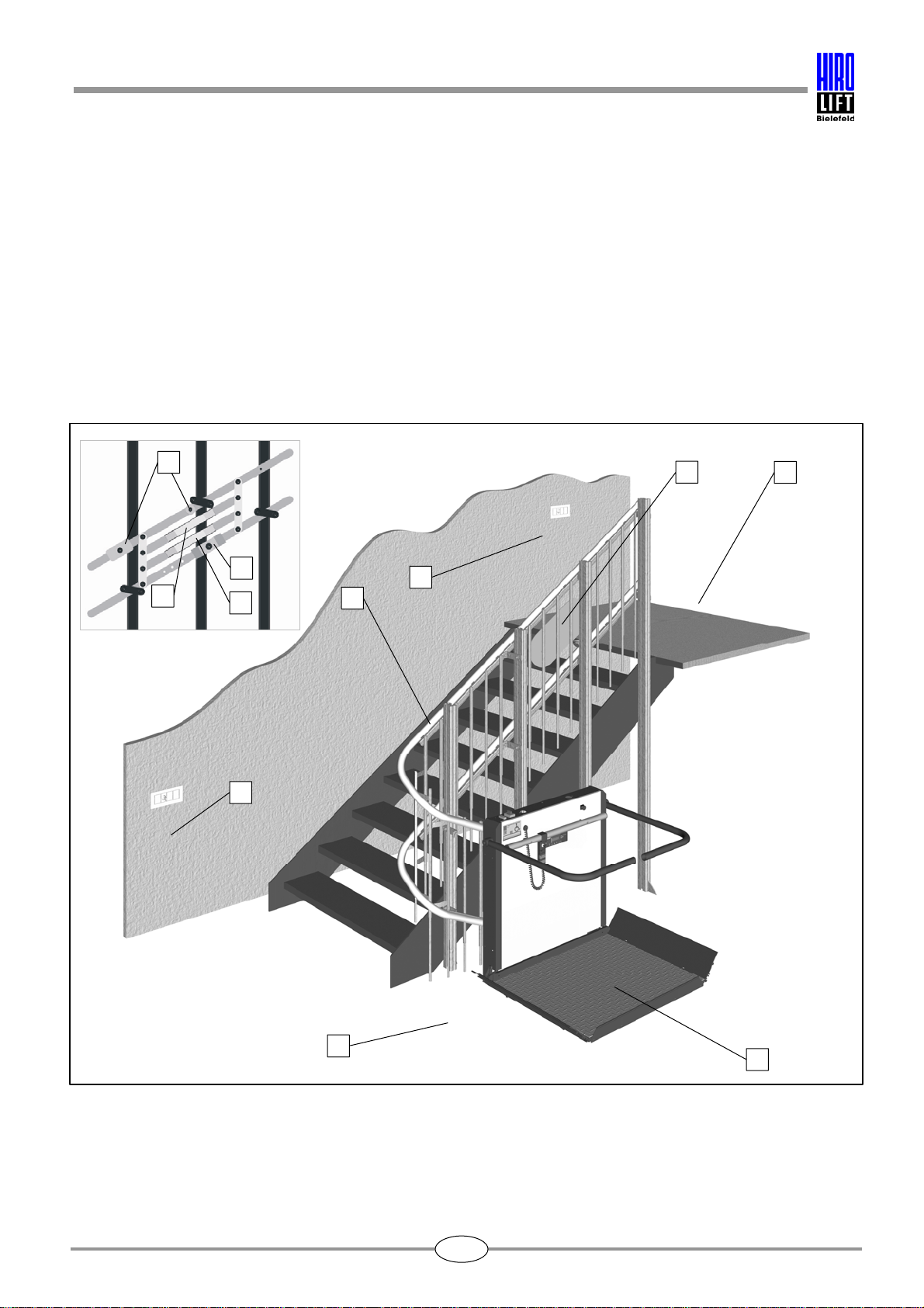
5.1 HIRO 320 — turning platform lift system
A Top access
B Bottom access
C Platform
D Remote control
E Top charging station
F Rails
G Magnets
H Actuating cam for emergency limit switch
I Guard cam
J Current collector cam/charging bar
Fig. 5.1: Platform lift system — Model 320
D
A
E
C
F
G
I
H
J
B
D
5. Summary of HIRO inclined lifts
10
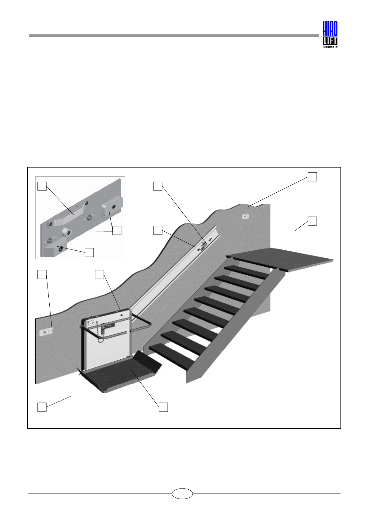
5.2 HIRO 350 — straight platform lift system
A Top access
B Bottom access
C Platform
D Remote control
E Top charging station
F Bottom charging station
G Guide rails
H Magnets
I Contact cam for emergency limit switch
J Current collector cam/charging bar
Fig. 5.2: Platform lift system — Model 350
E
A
D
CB
D F
G
J
I
H

5. Summary of HIRO inclined lifts
11
5.3 HIRO 360 — turning, lowerable platform lift system
A Top access
B Bottom access
C Platform
D Remote control
E Top charging station
F Bottom charging station
G Rails
H Magnets
I Contact cam for emergency limit switch
J Guard cam
K Current collector cam/charging bar
Fig. 5.3: Platform lift system — Model 360
DAE
CB
F
G
H
J
I
K
H
J
I
K
D

5. Summary of HIRO inclined lifts
12
5.4 HIRO 370 — turning, lowerable platform lift system
A Top access
B Bottom access
C Platform
D Remote control
E Top charging station
F Bottom charging station
G Rails
H Magnets
I Contact cam for emergency limit switch
J Guard cam
K Current collector cam/charging bar
Fig. 5.4: Platform lift system — Model 370
D
A
E
CB
D
F
G
H
J
I
K
H
J
I
K

5. Summary of HIRO inclined lifts
13
5.5 Platform components and accessories
A Platform with contact tray
B Access ramps with safety contact
C Safety barriers
D Main switch and fuses
E Type plate
F Platform control
G Display
H Emergency stop button
I Emergency button (optional)
K Key switch for lifts with
ON/OFF key switch.
L Lateral collision guard
Fig. 5.5: Platform components
D
A
E
C
B
F G
H
B
I
K
L
L

5. Summary of HIRO inclined lifts
14
A1 Remote control (key-operated)
A2 Remote control (model without key switch)
B Control light (LED)
C Key switch remote control
D Wall mounting for remote control
E Operation key
E2 ON/OFF key (for certain lifts)
E3 Key for electrically operated emergency
control facility (for certain lifts)
F Stationary remote control for wall
mounting (key operated)
G Key switch for stationary
remote control
H Charging device
Accessories for emergency evacuation:
I Hand wheel (for some types of lift)
J Allen key
K Torx screwdriver
L Square key
M Eye bolt
Fig. 5.6: Components of platform (not to scale)
The design of the individual components, such as the remote control unit or the charging
device, can vary. The functions remain the same, however.
A1
E1
C
B
F G
J
A2
B
H
D D
L
K
I
M
E2
E3

5. Summary of HIRO inclined lifts
15
5.6 Safety devices
HIRO platform lifts are equipped with a whole range of safety features to ensure safe use of the
systems:
Emergency stop button
In case of emergency you may push the emergency stop button any time. As soon as this button is
pushed, all movements of the system are stopped. After actuation the button remains locked in place.
In order to move the wheelchair lift again, the emergency stop button must be pulled out again.
Contact tray
The platform floor is equipped with a contact tray. The movement of the platform is stopped as soon as
the contact tray meets an obstruction, e.g. a bag put on the stairs.
The safety contact is released by reversing the direction of travel.
Lateral collision guard/contact strip
During travel the movement of the platform is stopped as soon as the side walls meet an obstruction.
The safety contact is released by reversing the direction of travel.
Access ramps with safety contact
During travel the movement of the platform is stopped as soon as the access ramps meet an
obstruction. This function is only activated when the access ramps are in their travel position (i.e. folded
upward at an angle of 45 degrees). The safety contact is released by reversing the direction of travel.
Safety barriers
The platform lift system is equipped with safety barriers that open and close automatically and protect
the user during travel.
Safety catch
Some of the wheelchair lifts have a safety catch device, which is fitted to the back of the housing on the
lower set of rollers behind the seat. This is activated automatically if the lift travels too fast.
With some of the wheelchair lifts, the design of the system makes it impossible for the lift to travel too
fast. In this case a safety catch device is not necessary.
Emergency limit switch
The emergency limit switch is located on the back of the housing. This switches the system off if the
platform travels beyond the end stop in the event of a fault. Additionally both ends of the track have
bumpers that prevent the platform from travelling beyond the stop.
Dead man's control
The lift can only be moved with permanent commands. When the command buttons are released the
system stops automatically.

5. Summary of HIRO inclined lifts
16
Control priorities
The platform control for the lift overrides the remote control. If the wheelchair lift is being operated via
the platform controls, operation via remote control is not possible.
Compact design
When the platform is folded away, its compact construction offers almost unrestricted use of the
available space.
Key switch/access control systems
The wheelchair lift system can only be set in operation via the key switch or in special cases via
alternative access control systems (see Section 6.2 "Key-operated systems", page 19).
Battery operation
Since the platform is powered by rechargeable batteries, it can still be used if there is a power failure.
Charging control
In order to prevent the rechargeable batteries from discharging, the platform lift system is equipped with
a warning device. If the platform does not return to a charging station after a set time, a warning signal
will be given.
Excess current cut-out
The barrier motors and the platform floor motor cut out automatically if they are inhibited (e.g. by an
obstruction) by means of overcurrent detection.
Rail heating system
Some outdoor lifts are fitted with a rail heating system to prevent the rails from icing over.
Safety catch heating system
All outdoor lifts with a safety catch device are fitted with a safety catch heating system to prevent the
safety catch from icing over.
Overload switch
An overload switch prevents the lift system from being used if the load is too high or is unevenly
distributed.

6. Operation of HIRO inclined lifts
17
Caution!
Before use or initial operation all users must be familiar with the operation of the
system. They have to be specially aware of the dangers which can occur through
incorrect use of the system!
6.1 Requirements for initial operation
• The mains plug of the power pack is connected to
a socket. An uninterrupted power supply is
guaranteed.
• The main switch and the fuses on the lifting
device have to be switched on.
Functions.
Main switch (A): Power supply to platform
F1 (B): Motor fuse
F2 (C): Charging fuse
• The batteries are fully charged.
• The emergency stop button is not pressed.
The platform lift is installed and ready for
operation.
In the case of wheelchair lifts with ON/OFF key
there are two key switches on the lift, whose
function will be described later (see Section 6.2,
page 19 and Section 7.1.2, page 59):
ON /OFF switch (E) with key (F)
Electrically operated emergency control facility (G)
Main switch (A)
Motor fuse (B)
Charging fuse (C)
Emergency operation (D)
In the case of lifts with ON/OFF key
switch, the key switch for ON/OFF may
be located in a laterally reversed
position to the ones shown in fig. 6.2,
depending upon the lift model.
Fig. 6.1: Main switch and fuses for lifts with
key-operated platform controls and remote controls
Fig. 6.2: Main switch, fuses and key switch for ON/OFF and
electrically operated emergency control facility for lifts with
ON/OFF key switch
B
C
A
D
BA
F
E
C
G
6. Operation of HIRO inclined lifts
18
As an example, the following pages show the operation of a HIRO 320 inclined wheelchair
lift with a turning platform lift system. Attention will be drawn to
differences to other models.
Depending on the site and due to technical changes your system may be different to the
pictures. For example a different number of charging stations may be available or the
operating controls may vary depending on customers' wishes.
The assignment of functions to the buttons on the remote control may differ from the ones
shown in these instructions, as the assignment of functions can vary widely to meet
customers' wishes.
Please familiarise yourself with your system before initial operation!
The platform lift has to be operated at least once a week.
6. Operation of HIRO inclined lifts
19
6.2 Key-operated systems
There are two different types of key-operated system available:
1. 1. Wheelchair lift with key-operated platform control and remote control
The platform controls and the remote control units have a key switch that can be turned to the "ON" or
"OFF" positions.
The key can only be removed when it is in the "OFF" position.
The wheelchair lift can only be operated via remote control if the key has been removed from the
platform controls.
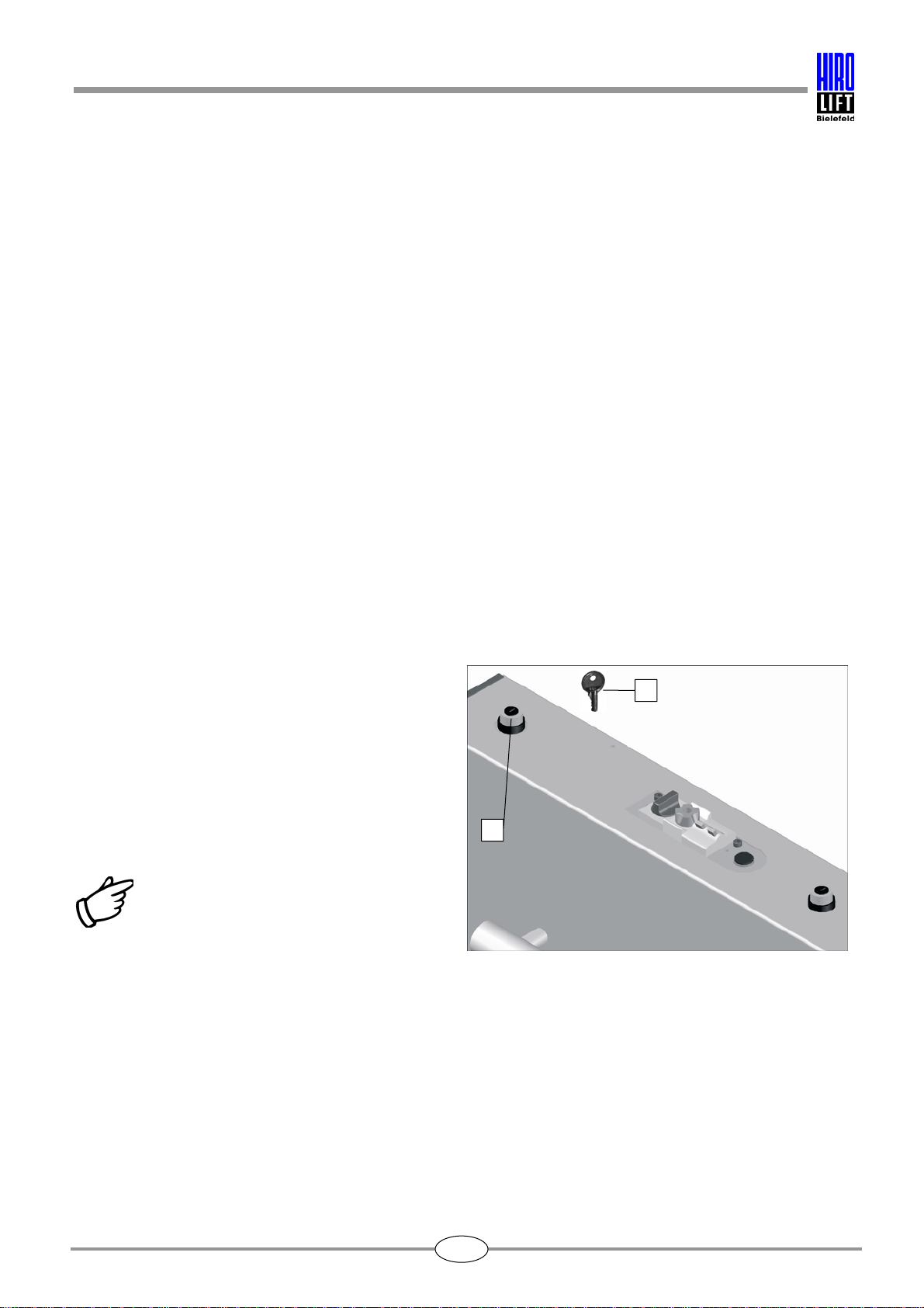
2. 2. Wheelchair lift with ON/OFF key switch (no key switch for remote control)
This key-operated system functions as follows:
• The lift system is fitted with a key switch which can be turned to the positions
"ON" and "OFF". The key can be removed in both positions.
• The remote control is not fitted with a key switch.
When the key (A) on the key switch (B) is turned to
the "ON" position:
• the wheelchair lift can be operated with the
platform controls, whether the key has been
removed or not.
• the wheelchair lift can neither be called nor
dispatched using the remote controls (which have
no key switch).
Advice!
When the platform controls are being
used, it is not possible to call or send
the lift via the remote control.
Please note that after you have finished
using the platform controls there is a
delay of a few seconds before the
wheelchair lift will respond to the
remote controls.
Fig. 6.3: Key switch for lifts with ON/OFF key
A
B
6. Operation of HIRO inclined lifts
20
When the key (A) on the key switch (B) is turned to the "OFF" position:
• the wheelchair lift cannot be set in motion using the platform controls, whether you have
removed the key or not.
• the wheelchair lift can be neither called nor dispatched using the remote controls (which have no key
switch).
Advice!
This type of key operation simplifies matters, since there are only two basic operating
conditions: either the wheelchair lift is switched on and can be operated, or the
wheelchair lift is switched off and cannot be operated.
Advice!
As a special version, alternative access control systems such as transponder systems,
code keypads, fingerprint readers or similar systems instead of a removable key are
possible. Appropriate sensor areas or panels are located on the lift and on the wall.
Please refer to the separate documentation supplied by the manufacturer concerned for
usage instructions.
Caution!
You may only use the stationary or portable remote control if you have a clear view
of the entire travel path of the wheelchair lift. If some sections of the travel path
cannot be seen, mirrors or similar aids must be installed to rectify this.
Caution!
The operator of the system is responsible for the safe and proper use of the lift.
Everyone who uses the wheelchair lift must be instructed in its use and be familiar
with the system. The operator of the system must ensure that the lift is only used, or
can only be used, by persons who have been briefed.
This is particularly important, because the wheelchair lift is ready for use if the key
has been set to the ON position and then removed.
Caution!
Always put the remote control unit back in its wall mount when not in use. The
operator of the system must ensure that unauthorised persons, such as children,
etc., cannot use the wheelchair lift. Otherwise, the lift must be switched off.
This manual suits for next models
6
Table of contents
Popular Lifting System manuals by other brands


Joab
Joab EcoDrive LA Operation and maintenance manual

Genie
Genie AWP Super Series 114002 Operator's manual

Lockhard
Lockhard Alulift M Operator's manual

WPG
WPG FLEX Series instructions

pela tools
pela tools 513949 manual

Aqua Creek
Aqua Creek PORTABLE PRO POOL-AT LIFT Installation and operating instructions