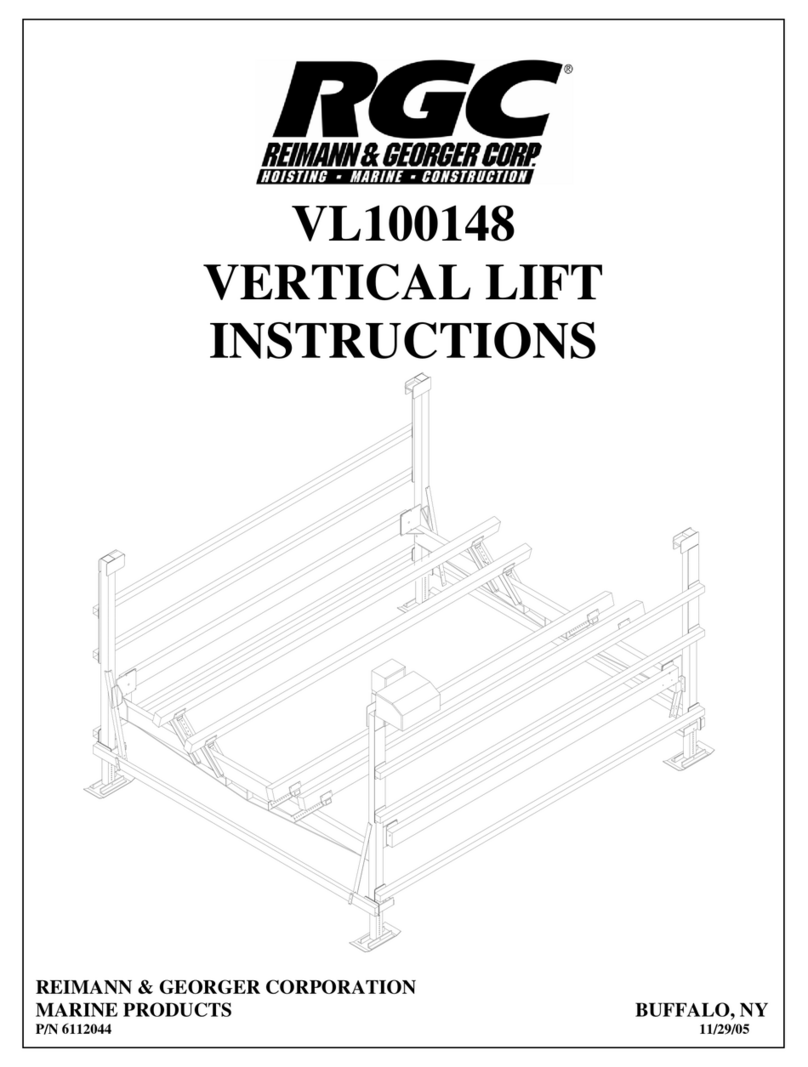
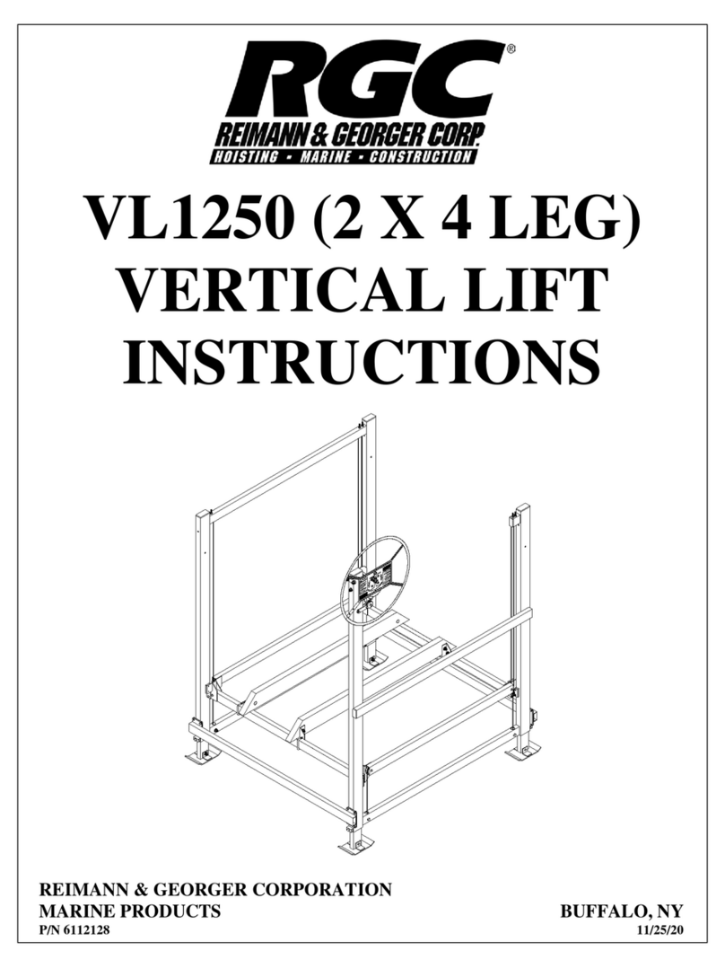
RGC VL16092 User manual

VL16092
VERTICAL LIFT
INSTRUCTIONS
REIMANN & GEORGER CORPORATION
MARINE PRODUCTS BUFFALO, NY
P/N 6112069 11/16/99

PRE-LIFTING CHECKLIST
The lift and related equipment must be thoroughly inspected prior to each use. Only those who have read and understood
this entire manual and related equipment manuals are qualified to do this inspection. This checklist is to be used as a
guideline in conjunction with the maintenance and inspection procedures outlined in this manual. It is recommended that
this checklist be maintained as a permanent record.
Insure the lift installation will clear all power lines and obstructions.
Insure all structural members of the lift are free of defects and damage that may affect the integrity.
Insure that an electric drive, if used, has been inspected and installed by a certified electrician in accordance with
local electrical codes. A Ground Fault Circuit Interrupter (G.F.C.I.) must be installed by your electrician and work
properly.
Insure that any user or dealer installed locking devices have been removed before operating the lift.
Operate the lift first without, and then with, your boat on the platform to test the operation of both the lift and the
winch.
Insure the boat is properly positioned on the lift before doing any raising or lowering.
Insure the lift is not being used beyond its rated capacity.
Insure any drain plug is in place on the boat before launching.
Conduct the wire rope inspection procedure described in Chapter 5 at least monthly.
Insure the leg pins connect the vertical legs to the adjustable legs. Insure the leg height has been properly adjusted
according to the water depth.
Insure the frame and platform fastenings are tight.
Insure the lower diagonal braces are installed in each corner.
Insure the frame is level and square according to the dimensions shown in Figure 3-6, Chapter 3.
Insure the cable end loops of the load and spreader tubes are fastened to the bracket at the bottom of each vertical
leg.
Insure the cable studs opposite the cable end loops in the platform assembly are tight. If tightening is needed,
follow the sequence described in Section 3.8 of Chapter 3. Then tighten the jam nuts to the cable nuts to lock the
position.
Insure the winch is securely fastened to vertical leg “A”.
Insure the handwheel has been attached to the winch hubplate.
Insure the spinner knob is attached to the handwheel using the preassembled hardware.
Insure the A-B load tube cable is properly reeved and fastened for correct winch operation.
Insure set screw or cable clamp securing wire rope end to the drum is tight and in good condition.
When facing the front of the handwheel, insure that the wire rope winds and unwinds from the right side of the
winch. This reeving will raise the platform when the handwheel is turned clockwise, and lower the platform when
the handwheel is turned counterclockwise. The brake pawl must click, meaning the brake is operative.
Insure all guards are in place before operating the winch.

PRE-LIFTING CHECKLIST (CONTINUED)
Insure the plastic caps are installed onto the tops of the vertical legs and the ends of the upper short horizontal tubes.
INSPECTOR: _____________________________________ DATE: ______________

TABLE OF CONTENTS
CHAPTER TITLE PAGE
RGC MARINE PRODUCTS 11/16/99 PHONE: (716) 895-1156
1 SAFETY.................................................................................................................................1
1.1 Introduction.............................................................................................................................1
1.2 Safety Definitions....................................................................................................................1
1.3 Equipment Safety Labels.........................................................................................................1
1.4 Equipment And Personnel Safety ...........................................................................................1
1.5 Installation Safety....................................................................................................................2
1.6 Operating Safety......................................................................................................................2
1.6.1 General ....................................................................................................................................2
1.6.2 Safety When Raising the Boat.................................................................................................3
1.6.3 Safety When Lowering the Boat .............................................................................................3
1.7 Maintenance and Storage Safety .............................................................................................3
2 SPECIFICATIONS...............................................................................................................5
2.1 Technical Data.........................................................................................................................5
2.2 Nameplate and Serial Number Tag..........................................................................................5
2.3 Optional Equipment.................................................................................................................5
3 INSTALLATION AND SETUP...........................................................................................7
3.1 Pre-Installation Checks............................................................................................................7
3.2 Prior To Setup .........................................................................................................................7
3.3 Vertical Leg Assembly............................................................................................................8
3.4 Frame Side Assembly..............................................................................................................9
3.5 Platform Assembly..................................................................................................................9
3.6 Mounting The Platform To The Frame .................................................................................10
3.7 Mounting The Lower Diagonal Braces.................................................................................11
3.8 Platform Reeving And Adjustment .......................................................................................12
3.9 Winch/Handwheel Mounting ................................................................................................13
3.10 Reeving The Winch...............................................................................................................14
3.11 Moving Lift To Operating Position.......................................................................................15
4 OPERATION.......................................................................................................................16
4.1 Before Operating The Lift.....................................................................................................16
4.2 Testing Winch Operation ......................................................................................................16
4.3 Raising And Lowering The Platform ....................................................................................17
4.4 Securing Lift When Not In Use.............................................................................................17
5 INSPECTION AND MAINTENANCE.............................................................................18
5.1 General Maintenance Rules...................................................................................................18
5.2 Wire Rope Inspection Procedure...........................................................................................18
5.3 Annual Inspection..................................................................................................................19
5.4 Annual Winch Maintenance..................................................................................................19
5.5 Storage Procedure..................................................................................................................20
6 TROUBLESHOOTING......................................................................................................21
7 PARTS LISTS.......................................................................................................................23
7.1 #3616000 VL 16092 Boat Lift Bundles................................................................................23
7.1.1 #3616020 VL 16092 Bundle 1 of 2.......................................................................................23
7.1.2 #3616021 VL 16092 Bundle 2 of 2.......................................................................................23
7.2 VL Extension Legs................................................................................................................23
7.3 #3679355 VL Bunk Carton of Parts......................................................................................23
7.4 #3603778 VL Bunk Bundle ..................................................................................................24

TABLE OF CONTENTS
CHAPTER TITLE PAGE
RGC MARINE PRODUCTS 11/16/99 PHONE: (716) 895-1156
7.5 #3616033 VL 16092 Carton of Parts.....................................................................................24
7.6 #3655255 VL Hardware........................................................................................................24
7.7 #3703811 VL Handwheel 4’.................................................................................................24
LIMITED WARRANTY ....................................................................................................25
LIST OF FIGURES
FIGURE DESCRIPTION PAGE
2-1 Typical Product Nameplate.....................................................................................................5
3-1 Vertical Lift Frame & Platform Assembly..............................................................................7
3-2 Lift / Dock Placement Options................................................................................................8
3-3 Vertical Leg Assembly............................................................................................................8
3-4 Frame Side Assembly..............................................................................................................9
3-5 Platform Assembly–Top View..............................................................................................10
3-6 Frame Squaring Assembly / Table ........................................................................................11
3-7 Lower Diagonal Brace Assembly..........................................................................................12
3-8 Cable Reeving & Adjustment................................................................................................ 13
3-9 VL Handwheel / Winch Mounting & Reeving......................................................................14
5-1 Wire Rope Components ........................................................................................................19

1 SAFETY
1.1 INTRODUCTION
Your Reimann & Georger Corporation Marine Products Aluminum Vertical Lift has been engineered to provide lifting
performance, long term economics and safety advantages that no other type can match. However, even a well-designed
and well-built lift can malfunction or become hazardous in the hands of an inexperienced and/or untrained user.
Therefore, read this manual and related equipment manuals thoroughly before operating your lift to provide maximum
safety for all operating personnel, and to get the maximum benefit from your equipment.
WARNING:
DO NOT OPERATE THIS LIFT WITHOUT STUDYING THIS ENTIRE MANUAL. FAILURE
TO DO THIS CAN LEAD TO EQUIPMENT MISUSE WITH RESULTING DAMAGE AND/OR
SERIOUS PERSONAL INJURY. CONTACT YOUR RGC®MARINE DEALER IF YOU HAVE
ANY QUESTIONS.
1.2 SAFETY DEFINITIONS
A safety message alerts you to potential hazards that could hurt you or others or cause property damage. The safety
messages or signal words for product safety signs are DANGER, WARNING, and CAUTION. Each safety message is
preceded by a safety alert symbol and is defined as follows:
DANGER: Indicates an imminently hazardous situation which, if not avoided, will cause death or serious injury. This
safety message is limited to the most extreme situations.
WARNING: Indicates a potentially hazardous situation which, if not avoided, could result in death or serious injury.
CAUTION: Indicates a potentially hazardous situation which, if not avoided, may result in minor or moderate injury. It
may also be used to alert against unsafe practices and property-damage-only accidents.
1.3 EQUIPMENT SAFETY LABELS
These labels warn you of potential hazards that could cause injury. Read them carefully. If a label comes off or becomes
illegible, contact a Reimann & Georger Corporation dealer for a free replacement.
1.4 EQUIPMENT AND PERSONNEL SAFETY
1. Do not use the lift if it shows any signs of damage.
2. Do not exceed the rated maximum lifting capacity of this equipment.
3. When using a direct drive or motorized friction drive, understand the use of all controls and connections provided
with it.
WARNING:
ALL ELECTRIC DRIVES MUST BE INSTALLED AND INSPECTED BY A CERTIFIED
ELECTRICIAN IN ACCORDANCE WITH LOCAL ELECTRICAL CODES. THIS
INSTALLATION MUST INCLUDE A PROPERLY WORKING GROUND FAULT CIRCUIT
INTERRUPTER. (G.F.C.I.)
4. Never try lifting anything other than a boat with this equipment.
1
5. Never allow people in the boat any time it is suspended above the water on the platform.

WARNING:
DO NOT STAND OR WALK ON THE PLATFORM WHILE IT IS IN ANY RAISED POSITION.
THIS CAN CAUSE SERIOUS PERSONAL INJURY.
6. Do not allow anyone to swim or play under, near or on the lift at any time.
1.5 INSTALLATION SAFETY
1. Insure that all bolts and nuts are fastened securely prior to operation.
2. Insure the pulleys spin freely. If any pulley binds, replace it immediately.
3. Do not weld or otherwise modify the lift. Such alterations may weaken the structural integrity of the lift and void the
warranty.
4. All lifting accessories such as pontoon brackets, pivoting bunks, and guide-ons, must be commercially manufactured,
have a rated load capacity equal to that of the lift, and be properly maintained and installed.
5. Insure that the frame is level and square.
6. The following precautions must be observed when lifting any part of this equipment:
a. Be sure of your footing.
b. Bend your knees and lift with your legs.
c. Hold the equipment section close to your body when lifting.
7. Wear heavy leather gloves when handling wire rope. Insufficient hand protection when handling wire rope can cause
personal injury.
1.6 OPERATING SAFETY
1.6.1 General
1. Never use this equipment beyond its rated capacity. This can damage the lift and/or boat with resulting serious
personal injury.
2. Before allowing anyone to operate the lift, be certain they fully understand the proper operating procedure.
3. Completely remove any user or dealer installed locking devices before operating the lift.
4. Follow the Pre-Lifting Checklist before operating.
5. Do not try lifting or launching your boat in rough water conditions. This can damage your boat and/or the lift.
6. The boat must be secured on the lift before raising or lowering. Failure to do this can cause equipment damage
and/or serious personal injury.
7. Keep people and pets clear during operation of the lift.
8. Keep fingers and clothing clear of all moving parts.
9. Check the lift periodically for frayed cables and/or binding pulleys.
10. Do not attempt to make any adjustments on the lift while it is being operated.
2

11. Contact your dealer if the winch mechanism fails to perform as described in the Operation chapter of this manual.
12. Never tamper with the winch mechanism. This can cause equipment damage.
13. Do not operate the lift under the influence of drugs, alcohol, or medication.
14. Never use the lift to hang or store any auxiliary equipment such as boating hardware.
1.6.2 Safety When Raising the Boat
1. The handwheel or power drive must turn clockwise when raising the platform. The brake pawl must click, indicating
that the brake is operative.
2. Do not try to raise the boat beyond the maximum lifting height of the platform.
WARNING:
IF YOU HAVE TO TURN THE HANDWHEEL COUNTERCLOCKWISE TO RAISE THE
PLATFORM, YOU HAVE REEVED THE WINCH INCORRECTLY. YOU WILL
IMMEDIATELY ENCOUNTER STRONG RESISTANCE WHICH CAN LEAD TO WINCH
DAMAGE AND/OR CABLE BREAKAGE.
1.6.3 Safety When Lowering the Boat
1. The handwheel or power drive must turn counter-clockwise when lowering the platform.
WARNING:
IF YOU HAVE TO LOWER THE PLATFORM BY TURNING THE HANDWHEEL
CLOCKWISE, YOU HAVE REEVED THE WINCH INCORRECTLY. THE BRAKE PAWL
WILL NOT BE EFFECTIVE WHICH CAN CAUSE AN UNCONTROLLED SPIN-DOWN OR
“FREEWHEEL” OF THE HANDWHEEL. IF FREEWHEELING OCCURS, NEVER TRY TO
STOP IT.
2. Counter-clockwise rotation of the handwheel allows the self-activating brake mechanism to provide a controlled
lowering of the platform.
WARNING:
NEVER RELEASE THE BRAKE PAWL OF THE WINCH. THIS CAN TRIGGER AN
UNCONTROLLED SPIN-DOWN OR “FREEWHEEL” OF THE HANDWHEEL.
3. Do not continue lowering the platform after the boat floats freely. Excessive slack in winch cable may cause
binding.
1.7 MAINTENANCE AND STORAGE SAFETY
1. At least once a year, the lift must be thoroughly inspected as described in the Maintenance chapter of this manual.
2. Completely lower the platform before performing any type of maintenance or repair.
3

WARNING:
NEVER ALLOW ANYBODY TO WORK IN OR ON THE BOAT WHEN IT IS SUSPENDED
ABOVE THE WATER ON THE LIFT.
3. Immediately replace any components found to be defective as described in Chapter 5—Inspection and Maintenance.
4

2 SPECIFICATIONS
2.1 TECHNICAL DATA
MODEL VL16092
Weight Capacity 1600 lbs.
Maximum Beam 92”
Lifting Height 66”
Overall Width (Including Feet) 100”
Overall Length (Including Feet) 108”
12’ Full Length Bunks Std.
S.S. Aircraft Cable Std.
Polymer Sheaves Std.
K-2550 Winch Std.
S.S. Hardware Std.
4’ Solid Aluminum Handwheel Std.
DRIVE TYPE OPTIONS
Friction Drive AC 110V Opt.
Friction Drive DC 12V Opt.
Approx. Shipping Weight 440 lbs.
2.2 NAMEPLATE AND SERIAL NUMBER TAG
It is important to identify your lift completely and accurately whenever ordering spare parts or requesting assistance in
service. The lift has a product nameplate located at the top of vertical leg “D”. The label shows the model and serial
numbers and capacity rating. The lift label should appear as the sample nameplate shown in Figure 2-1. Record the serial
number for future reference.
5
BOAT LIFT
CAP. lbs.
MODEL
SERIAL NO.
Figure 2-1.
Typical Product Nameplate
MODEL VL16092
SERIAL NUMBER ____________________
CAPACITY RATING 1600 LBS.

6
2.3 OPTIONAL EQUIPMENT
The following options are available which enable you to customize your lift for your particular operation. Installation
instructions are provided as part of each option kit.
1. Acrylic Canopy— Boats tucked neatly under the heavy duty canopy are protected from the elements, reducing the
need for boat coverings. Various canopy sizes and colors are available.
2. Friction Drive—Motorized drive turns standard handwheel to raise and lower boat.
3. Full Length Guide-On—Cushioned guide-ons make entering the lift easy in various water conditions.
4. Motor Stop—Assists in positioning boat on the lift for balanced lifting.
5. VL Transport Kit—Makes installation and removal of boat lift easier. You can purchase the complete kit or
desired components.
6. Pontoon Deck Brackets—These brackets are designed to lift pontoon boats from under the deck. The vertical leg
bumper kit is included which supplies carpeted side bumpers. Wood for bunks is not supplied.
7. Pontoon Cradles—Cradle brackets designed for lifting pontoon boats from under the pontoons. The vertical leg
bumper kit is included which supplies carpeted side bumpers. Wood for bunks is not supplied.
8. Deep Water Extension Legs—Adjustable legs available in pairs with bracing. Standard lengths are 4’, 6’, 8’, and
10’.
9. VL Upper / Lower Bumper Kit—This cushioned wood kit mounts onto your lift in key locations to protect your
boat while entering and exiting the lift in various water conditions. This is both a “stand alone” kit and a kit
automatically supplied with the pontoon deck brackets and pontoon cradles.

3 INSTALLATION AND SETUP
3.1 PRE-INSTALLATION CHECKS
1. Do not assemble the lift if any part shows any sign of damage.
2. Do not weld or otherwise modify the lift. Such alterations may weaken the structural integrity of the lift and void the
warranty.
3. All lifting accessories such as pontoon brackets, pivoting bunks, guide-ons, and slings shall be commercially
manufactured, have a rated load capacity equal to that of the lift, and be properly maintained and installed. Consult
the manufacturer’s separate instructions provided for these accessories.
WARNING:
ALL ELECTRIC DRIVES MUST BE INSTALLED AND INSPECTED BY A CERTIFIED
ELECTRICIAN IN ACCORDANCE WITH LOCAL ELECTRICAL CODES. THIS
INSTALLATION MUST INCLUDE A PROPERLY WORKING GROUND FAULT CIRCUIT
INTERRUPTER. (G.F.C.I.)
3.2 PRIOR TO SETUP
The part reference numbers and letters used in the subassembly drawings of sections 3.3 through 3.9 are the same as those
shown in Figure 3-1 and listed in the parts lists of Chapter 7.
Figure 3-1.
Vertical Lift Frame & Platform Assembly
7

The lift may be placed on either side of your dock as shown in Figure 3-2. The winch is mounted onto vertical leg A.
Figure 3-2
Lift / Dock Placement Options
Place one bag of hardware at each corner.
CAUTION:
INSERT ALL BOLTS FROM THE INSIDE OF THE LIFT TO PREVENT DAMAGE TO YOUR
BOAT. THE NUTS FASTEN ONTO THE OUTSIDE FACE OF THE LIFT. THE ONLY
BOLTS THAT MAY BE INSERTED FROM THE OUTSIDE OF THE LIFT ARE THOSE ON
THE BOTTOM PARTS OF THE BRACES.
3.3 VERTICAL LEG ASSEMBLY
1. Refer to Figure 3-3. Fasten an extension leg onto each of the foot plates using supplied hardware. Insert these
subassemblies into the bottoms of each of the vertical legs A, B, C, and D.
2. Connect the extension legs to the vertical legs with supplied VL Hitch Pins. Adjust the leg height according to water
depth: the deeper the legs are in the water, the higher the vertical legs should be mounted onto the extension legs.
Figure 3-3
Vertical Leg Assembly
8

3.4 FRAME SIDE ASSEMBLY
1. Refer to Figure 3-4. Fasten a pair of short horizontal tubes between vertical legs A and D with hardware shown. DO
NOT TIGHTEN.
2. Repeat the procedure for vertical legs B and C.
3. Lay the assembled sides down on the ground with the foot plates facing one another and aligned, about 9 feet apart.
4. Square the side assemblies by adjusting the verticals to achieve the same measured distance between them at both top
and bottom. Refer to “Y” Dim. in Figure 3-6. Tighten all fasteners. Remeasure and align if necessary.
Figure 3-4
Frame Side Assembly
3.5 PLATFORM ASSEMBLY
1. Refer to Figure 3-5. Position both load tubes and spreader tubes on the ground as shown in the diagram.
2. Carefully remove the 5/8” hex nut and washers, if supplied, from each end of both spreader tubes, but DO NOT
remove the bolts from the tubes. This will prevent the sheaves from falling out.
3. At each corner of the platform, align the holes in the spreader tube with the holes in the load tube. Fasten the tubes
together. Then refasten the 5/8” hex nut and washers, if supplied.
9

Figure 3-5
Platform Assembly – Top View
3.6 MOUNTING THE PLATFORM TO THE FRAME
1. Insure all platform fastenings are tight before mounting onto the frame.
2. Lift one of the frame sides and position it along a spreader tube side of the platform.
3. Place a platform corner onto each of the foot plates so that the frame side stands.
4. Repeat Steps 2 and 3 for the other side of the lift.
CAUTION:
THE LOAD AND SPREADER TUBES OF THE PLATFORM ARE ALREADY REEVED. WHEN
PLACING THE ASSEMBLED PLATFORM INTO THE FRAME, INSURE THE CABLE LOOPS
ARE PASSING OVER THE SHEAVES AND POINTING TOWARDS THE BOTTOM BRACKET
OF EACH VERTICAL LEG. EQUIPMENT MALFUNCTION AND DAMAGE WILL RESULT
IF THE PLATFORM IS NOT ORIENTED THIS WAY.
5. Fasten a long horizontal tube across each end to connect the two sides using hardware shown in Figure 3-4. DO
NOT TIGHTEN.
6. Square the frame by adjusting the verticals to achieve the same measured distance between them at both top
and bottom. Refer to “X” Dim. in Figure 3-6. Tighten all fasteners. Remeasure and align if necessary.
10

7. Install the eight (8) plastic caps provided onto the tops of the four vertical legs and the ends of the upper short
horizontal tubes.
MODEL “X” DIM “Y” DIM
VL16092 92 IN. 90 IN.
Note: Values shown are approx.
Figure 3-6
Frame Squaring Assembly / Table
3.7 MOUNTING THE LOWER DIAGONAL BRACES
1. Position a lower diagonal brace on the inside of vertical leg “B” as shown in Figure 3-7. Loosely fasten with
hardware shown.
2. Position the opposite end along the long horizontal tube so that the tube is situated between the two holes located in
the lower diagonal brace. Place a 3-hole plate onto the outside face of the horizontal tube.
3. Align the holes and fasten in place.
4. Repeat Steps 1 through 3 for each corner.
CAUTION:
THE FOUR LOWER DIAGONAL BRACES ARE MOUNTED ONLY TO THE TWO LONG
HORIZONTAL TUBES. NEVER TRY TO MOUNT THESE BRACES TO ANY OF THE SHORT
HORIZONTAL TUBES.
5. Insure the frame is square and that it satisfies the dimensions shown in Figure 3-6. About 1/4 to 1/2 inch difference
between the upper and lower measurements is permitted.
11

Figure 3-7
Lower Diagonal Brace Assembly
3.8 PLATFORM REEVING AND ADJUSTMENT
1. Position the platform near the bottom end of its lifting range. Insure the platform is level.
2. Refer to Figure 3-8. The load and spreader tubes are already reeved. Fasten the cable end loops to the bracket
provided at the bottom of each of the four vertical legs.
CAUTION:
DO NOT “JAM TIGHT” THESE LOWER CABLE ANCHORS OR YOU WILL BREAK OFF THE
BRACKET PLATES.
CAUTION:
WEAR HEAVY LEATHER GLOVES WHEN HANDLING WIRE ROPE. FAILURE TO DO
THIS CAN CAUSE SERIOUS PERSONAL INJURY.
3. Using a 7/8” open-end wrench, tighten the cable studs opposite the cable end loops in the following order. The
following step numbers correspond to the step numbers shown in Figure 3-8.
Step 1: Tighten down the nut to add tension to the B-C spreader tube cable.
Step 2: Tighten down the nut to add tension to the A-D spreader tube cable. Check that the B-C and A-D spreader
tube cables are equal in tension and that the platform is level.
Step 3: Tighten down the nut to add tension to the first C-D load tube cable.
Step 4: Tighten down the nut to add tension to the second C-D load tube cable. Check that both C-D load tube cables
are equal in tension and that the platform is level.
4. Add and tighten the jam nuts to the cable nuts to lock the position.
5. During operation, when the platform is being lifted, it is normal for the two cables in the C-D load tube to alternate
from being tense to going slack. If you notice this, it is not necessary to further tighten down the nuts.
12

Figure 3-8
Cable Reeving & Adjustment
6. If the boat is not lifting level because the stern is lifting higher or lower than the bow, the spreader tube cables are not
tight enough. Repeat the first two substeps under Step 3 above.
3.9 WINCH / HANDWHEEL MOUNTING
1. Refer to Figure 3-9. Attach winch to vertical leg “A” approximately 12 inches below the top of the leg. Lightly
fasten with clamps. The handwheel adapter plate should be facing away from the lift as shown.
2. Attach the handwheel to the handwheel adapter plate.
3. Attach the spinner knob to the handwheel using the preassembled hardware. Select the hole that is most comfortable
for lowering the lift.
13

CAUTION:
DO NOT USE THE SPINNER KNOB FOR LIFTING THE BOAT. THIS CAN CAUSE
EQUIPMENT DAMAGE.
Figure 3-9
VL Handwheel / Winch Mounting and Reeving
3.10 REEVING THE WINCH
1. Refer to Figure 3-8. Attach the A-B load tube cable stud to vertical leg “B” .
2. Refer to Figure 3-9 Starting from the bottom of winch, reeve the cut end of cable between drum and winch mounting
frame. Wrap cable over top of drum, through hole in RIGHT SIDE of drum flange and under cable clamp, with one
inch of cable extending past clamp.
3. Fasten cable in place by tightening the nuts with lockwashers attached to clamp.
4. Adjust winch mounting height and cable stud attachment on vertical leg “B” to provide a minimum of 3 wraps of
cable on drum before any load is lifted. Tightly fasten winch mounting hardware and jam nut on cable stud end when
complete
14

WARNING:
WHEN REEVING THE WINCH, CLOCKWISE ROTATION OF THE HANDWHEEL MUST
RAISE, NOT LOWER, THE PLATFORM. IF CLOCKWISE ROTATION OF THE
HANDWHEEL LOWERS THE PLATFORM, YOU HAVE REEVED THE WINCH
INCORRECTLY. AN UNCONTROLLED FREEWHEELING CAN BE TRIGGERED WITH
THE WEIGHT OF A BOAT.
FREEWHEELING CAN CAUSE EQUIPMENT OR BOAT DAMAGE. HOWEVER, IF
FREEWHEELING OCCURS, NEVER TRY TO STOP IT. THIS CAN CAUSE SERIOUS
PERSONAL INJURY.
3.11 MOVING LIFT TO OPERATING POSITION
1. The following precautions must be observed when moving your lift for any reason:
a. Be sure of your footing.
b. Bend your knees and lift with your legs.
c. Hold the lift section close to your body when lifting.
2. After moving your lift to the operating position, insure that the frame is square and that the lift sets level.
CAUTION:
SEVERE OUT OF LEVEL INSTALLATION MAY CAUSE BINDING, RESULTING IN
EQUIPMENT DAMAGE.
CAUTION:
FRAME MUST BE SQUARE TO PREVENT DAMAGE AND/OR IMPROPER FITTING OF
CANOPY FABRIC IF SO EQUIPPED.
3. Verify frame is square by measuring the diagonal distance from the outside of frame corner to opposite corner. Repeat for
alternate corners. The difference between the two measurements shall not exceed 1/4 of an inch.
Frame Diagonal Measurement Diagram
(Measure to Outside Corners)
15
Table of contents
Other RGC Lifting System manuals
Popular Lifting System manuals by other brands

Titan Ramps
Titan Ramps 311410 Operator's manual

Aquatec
Aquatec orca Assembly instructions

R. Beck Maschinenbau
R. Beck Maschinenbau HS 2000 LARGE FH operating manual

Peak
Peak AMGO 414 Installation and service manual

Ravaglioli
Ravaglioli KPH 374 A manual

ReadyLift
ReadyLift 66-2215 installation instructions