Hirschmann Dragon PTN User manual

Installation Dragon PTN Nodes Technical support
Release 01 02/2018 https://hirschmann-support.belden.com
User Manual
Installation
Dragon PTN
Node PTN2210: 1 NSM, 2 PSUs, 2 CSMs, 10 IFMs
Node PTN2209: 1 NSM, 2 PSUs, 2 CSMs, 9 IFMs
Node PTN2206: 1 NSM, 2 PSUs, 2 CSMs, 6 IFMs
Node PTN1104: 1 NSM, 1 PSU, 1 CSM, 4 IFMs

2 Installation Dragon PTN Nodes
Release 01 02/2018
The naming of copyrighted trademarks in this manual, even when not specially indicated, should not
be taken to mean that these names may be considered as free in the sense of the trademark and
tradename protection law and hence that they may be freely used by anyone.
© 2018 Hirschmann Automation and Control GmbH
Manuals and software are protected by copyright. All rights reserved. The copying, reproduction,
translation, conversion into any electronic medium or machine scannable form is not permitted,
either in whole or in part. An exception is the preparation of a backup copy of the software for your
own use.
The performance features described here are binding only if they have been expressly agreed when
the contract was made. This document was produced by Hirschmann Automation and Control GmbH
according to the best of the company's knowledge. Hirschmann reserves the right to change the
contents of this document without prior notice. Hirschmann can give no guarantee in respect of the
correctness or accuracy of the information in this document.
Hirschmann can accept no responsibility for damages, resulting from the use of the network
components or the associated operating software. In addition, we refer to the conditions of use
specified in the license contract.
You can get the latest version of this manual on the Internet at the Hirschmann product site
(www.hirschmann.com).
Hirschmann Automation and Control GmbH
Stuttgarter Str. 45-51
72654 Neckartenzlingen
Germany

Installation Dragon PTN Nodes 3
Release 01 02/2018
Contents
1. INTRODUCTION ......................................................................................................... 6
1.1 General...............................................................................................6
1.2 Manual References .............................................................................6
2. NODE DESCRIPTION ................................................................................................... 8
2.1 General...............................................................................................8
2.1.1 Node XT-2210-A.........................................................................................8
2.1.2 Node XT-2209-A.........................................................................................8
2.1.3 Node XT-2206-A.........................................................................................9
2.1.4 Node XT-1104-A.........................................................................................9
2.2 NSM (=Node Support Module) ............................................................9
2.2.1 General ......................................................................................................9
2.2.2 Functions .................................................................................................10
2.2.3 PoE (=Power Over Ethernet) (only on NSM-A)........................................15
2.3 PSU (=Power Supply Unit) ................................................................. 17
2.3.1 Node PSUs................................................................................................17
2.3.2 PoE PSUs (only on NSM-A).......................................................................20
2.4 CSM (=Central Switching Module) ..................................................... 24
2.4.1 General ....................................................................................................24
2.4.2 CSM Redundancy.....................................................................................24
2.5 IFM (=Interface Module) ...................................................................24
2.6 Backplane......................................................................................... 25
2.7 PE: Protective Earth .......................................................................... 25
2.8 Cooling / Temperature Sensing .........................................................26
2.9 Add a New Node to a Live Network................................................... 26
3. SPECIFICATIONS....................................................................................................... 27
3.1 General Specifications....................................................................... 27
3.2 Weight..............................................................................................27
3.3 MTBF................................................................................................27
3.4 Power Consumption (Empty Node) ...................................................27
3.5 Dimensions.......................................................................................27
3.6 Cooling ............................................................................................. 28
3.7 Input Voltage Range .........................................................................28
3.8 Digital Output Contacts..................................................................... 28
3.9 Ordering Information........................................................................28
4. INSTALLATION INSTRUCTIONS.................................................................................. 28
5. WEEE GUIDELINES.................................................................................................... 29
6. ABBREVIATIONS ...................................................................................................... 29

4 Installation Dragon PTN Nodes
Release 01 02/2018
List of figures
Figure 1 Dragon PTN MPLS-TP Network........................................................................................ 6
Figure 2 XT-2210-A Node .............................................................................................................. 8
Figure 3 XT-2209-A Node .............................................................................................................. 8
Figure 4 XT-2206-A Node .............................................................................................................. 9
Figure 5 XT-1104-A Node .............................................................................................................. 9
Figure 6 NSM-A, NSM-B: Front Panel.......................................................................................... 10
Figure 7 NSM-A: Side View.......................................................................................................... 11
Figure 8 Example: Node Number 219 ......................................................................................... 11
Figure 9 DI, DO RJ45 Connector .................................................................................................. 13
Figure 10 Example: Digital Input (=DI): Closed Input .................................................................. 14
Figure 11 DO Contact Behavior: No Alarm/Alarm....................................................................... 15
Figure 12 Alarming via Digital Output (=DO) Contacts................................................................ 15
Figure 13 General PoE Example .................................................................................................. 16
Figure 14 ACP-A PSU with Power Cable ...................................................................................... 17
Figure 15 DCP-A PSU (18-60VDC) / Power Cable / Code Keys .................................................... 18
Figure 16 DCP-B PSU (88-300VDC) / Power Cable / Code Keys .................................................. 19
Figure 17 ACPoE-A PSU to NSM-A Connection ........................................................................... 21
Figure 18 Output Current, Power Derating................................................................................. 22
Figure 19 DCPoE-A PSU to NSM Connection............................................................................... 23
Figure 20 XT-2210-A: Node Slot Speeds...................................................................................... 24
Figure 21 XT-2209-A: Node Slot Speeds...................................................................................... 25
Figure 22 XT-2206-A: Node Slot Speeds...................................................................................... 25
Figure 23 XT-1104-A: Node Slot Speeds...................................................................................... 25
Figure 24 PE: Protective Earth..................................................................................................... 26
Figure 25 Crossed-Bin Symbol..................................................................................................... 29
List of Tables
Table 1 Manual References........................................................................................................... 7
Table 2 Product Ordering Numbers .............................................................................................. 7
Table 3 LED Indications in Boot Operation.................................................................................. 12
Table 4 LED Indications in Normal Operation ............................................................................. 12
Table 5 DI Pin Allocation.............................................................................................................. 13
Table 6 DO Pin Allocation............................................................................................................ 14
Table 7 DCP-A PSU (18-60VDC) / Power Cable / Code Keys........................................................ 18
Table 8 DCP-B PSU (88-300VDC) / Power Cable / Code Keys...................................................... 19
Table 9 Specifications: ACP-A PSU (100-240VAC± 10%) ............................................................. 20
Table 10 Specifications: DCP-A PSU (18-60VDC)......................................................................... 20
Table 11 Specifications: DCP-B PSU (88-300VDC) ....................................................................... 20
Table 12 Specifications: ACPoE-A PSU......................................................................................... 22
Table 13 Specifications: DCPoE-A PSU ........................................................................................ 23
Table 14 Product Weights ........................................................................................................... 27

Installation Dragon PTN Nodes 5
Release 01 02/2018
Table 15 Power Consumption ..................................................................................................... 27
6 Installation Dragon PTN Nodes
Release 01 02/2018
1. INTRODUCTION
1.1 General
This document is valid as of Dragon PTN Release 3.0DR.
The Dragon PTN product line has been designed for industrial MPLS-TP networks and con-
sists of node types XT-2210-A, XT-2209-A, XT-2206-A and XT-1104-A. The Dragon PTN Nodes
have a rugged industrial design and operate entirely fanless (no moving parts, except for the
9-L3A-L IFM (see Ref.[6] in Table 1)) and are compliant with the EMC standards listed in
Ref.[5] in Table 1. All nodes are modular and 19” Rack or DIN Rail mountable. The more
compact XT-1104-A and XT-2206-A node require an extra DIN Rail 19” rack mount kit for rack
installation, see also Table 2 and Ref.[2] in Table 1 for an overview of the possible mounting
kits.
All nodes are equipped with a Node Support module (=NSM), which hosts functions like I/O
contacts and inputs for external PoE (=Power Over Ethernet, only on NSM-A) power supplies.
A node requires at least an NSM, one power supply unit (=PSU) and one central switching
module (=CSM). Each node provides a number of slots for interface modules to communi-
cate with applications like Ethernet, SHDSL, E1/T1, C37.94 ...
Node XT-1104-A is ultra-compact and can host a single PSU and CSM and has 4 interface
slots. Node XT-2210-A can be equipped with dual PSUs and dual CSMs for redundancy pur-
poses and has 10 interface slots. Node XT-2206-A is similar to node XT-2210-A but offers 6
interface slots instead of 10. XT-2209-A is similar to XT-2210-A but is optimized for the 9-
L3A-L IFM, see Ref[6] in Table 1.
Nodes can be interconnected via copper cable or optical fiber.
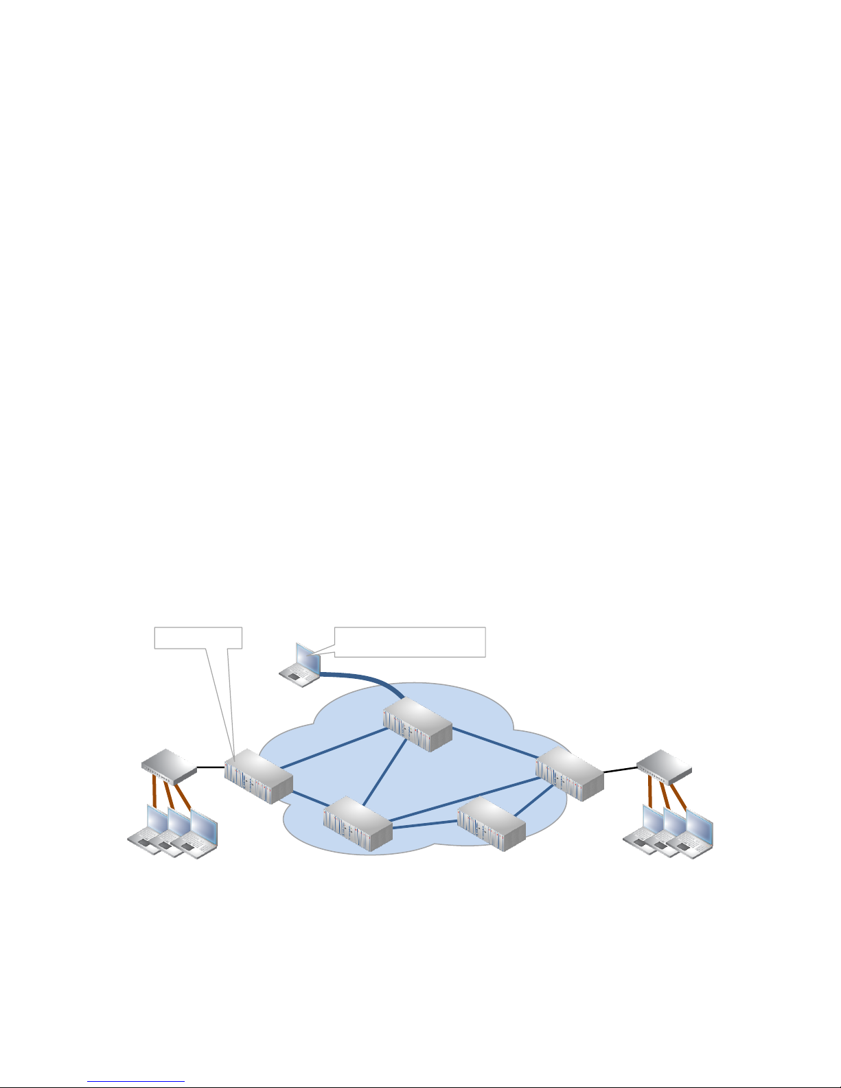
An example of a Dragon PTN network can be found in the figure below. The network is man-
aged by a HiProvision PC (=Dragon PTN Management System), see also Ref. [1] in Table 1.
Figure 1 Dragon PTN MPLS-TP Network
1.2 Manual References
Table 1 is an overview of the manuals referred to in this manual. ‘&’ refers to the language
code, ‘*’ refers to the manual issue. All these manuals can be found in the HiProvision
(=Dragon PTN Management System) Help function. Table 2 shows the ordering numbers.
router router
HiProvision PC
(=Dragon PTN Management)
Dragon PTN
MPLS-TP Network
Dragon PTN Node

Installation Dragon PTN Nodes 7
Release 01 02/2018
Table 1 Manual References
Ref.
Number
Title
[1]
DRA-DRM821-&-*
Dragon PTN and HiProvision Operation
[2]
DRA-DRM801-&-*
Dragon PTN Installation and Operation
[3]
DRD-DRM803-&-*
Dragon PTN Central Switching Module: PTN-CSM310-A
[4]
DRE-DRM807-&-*
Dragon PTN Interface Module: PTN-4-GC-LW/ PTN-4-GCB-LW
[5]
DRA-DRM810-&-*
Dragon PTN General Specifications
[6]
DRE-DRM823-&-*
Dragon PTN Interface Module: PTN-9-L3A-L
Table 2 Product Ordering Numbers
Ordering Number
Description
942 228-004
Node: PTN2210 (NSM not included)
942 228-003
Node: PTN2209 (NSM not included)
942 228-002
Node: PTN2206 (NSM not included)
942 228-001
Node: PTN1104 (NSM not included)
942 256-001
19 Inch Rack Mount Kit for PTN2206
942 256-003
19 Inch Rack Mount Kit for PTN1104
942 256-004
19 Inch Rack Mount Kit for 2x PTN1104
942 256-002
Heavy duty DIN Rail kit for PTN2206
942 256-005
Heavy duty DIN Rail kit for PTN1104
942 229-001
Node Support Module (PTN-NSM-A)
942 229-002
Node Support Module (PTN-NSM-B)
942 234-001
PTN-ACP-A: AC PSU 100 to 240 VAC ± 10 %
942 234-002
PTN-DCP-A: DC PSU 18 to 60 VDC
942 234-003
PTN-DCP-B: DC PSU 88 to 300 VDC
942 235-001
PTN-ACPoE-A: External DIN rail PSU (=AC 100-240 VAC Wide-range Input)
942 235-002
PTN-DCPoE-A: External DIN rail PSU (=33-62V Input)
942 237-001
PTN-BLANK-Module: Empty IFM cover plate
942 237-002
PTN-BLANK-PSU: Empty PSU cover plate
942 237-003
PTN-BLANK-CSM: Empty CSM cover plate
942 256-100
Europe: AC PSU Cable with locking mechanism (2.5m) for AC PSU 100 to 240 VAC ± 10 %
942 256-101
UK: AC PSU Cable with locking mechanism (2.5m) for AC PSU 100 to 240 VAC ± 10 %
942 256-102
US: AC PSU Cable with locking mechanism (2.5m) for AC PSU 100 to 240 VAC ± 10 %
942 256-105
Cable (3m) to connect External DIN rail PoE PSU to the NSM
942 256-103
DC PSU Cable (3m) with coding keys for DC PSU 18 to 60 VDC
942 256-104
DC PSU Cable (3m) with coding keys for DC PSU 88 to 300 VDC

8 Installation Dragon PTN Nodes
Release 01 02/2018
2. NODE DESCRIPTION
2.1 General
The Dragon PTN node consists of a 3 U (3 U = 132.5 mm = 5.22 inches) high, 19 inches rack
or DIN rail mountable stainless steel (*) chassis. The EMC shielding of the chassis complies
with the EMC standards listed in Ref.[5] in Table 1. Each node type has a modular structure.
Depending on the customer needs, different node types are available, see paragraphs be-
low.
NOTE: (*) Stainless steel according EN A2 1.4016.
2.1.1 Node XT-2210-A
The following modules can be installed from left to right (see Figure 2):
Node Support Module (NSM);
2 Power Supply Units (PSU-1/PSU-2);
10 Interface Modules (IFM-1,…, IFM-10);
2 Central Switching Modules (CSM-1/CSM-2);
Figure 2 XT-2210-A Node
2.1.2 Node XT-2209-A
The following modules can be installed from left to right (see Figure 2):
Node Support Module (NSM);
2 Power Supply Units (PSU-1/PSU-2);
1 wide IFM slot (IFM-3) meant for a 9-L3A-L IFM (wider than normal IFMs). This slot (left-
hand side) can also be used for normal IFMs;
9 Interface Modules (IFM-1,…, IFM-9);
2 Central Switching Modules (CSM-1/CSM-2);
Figure 3 XT-2209-A Node
NSM PSU-1 PSU-2 CSM-1 CSM-2
IFM-1 IFM-2 IFM-3 IFM-4 IFM-5 IFM-6 IFM-7 IFM-8 IFM-9 IFM-10
NSM PSU-1 PSU-2 CSM-1 CSM-2
IFM-1 IFM-2 IFM-3 IFM-5 IFM-6 IFM-7 IFM-8 IFM-9 IFM-10

Installation Dragon PTN Nodes 9
Release 01 02/2018
2.1.3 Node XT-2206-A
The following modules can be installed from left to right (see Figure 2):
Node Support Module (NSM);
2 Power Supply Units (PSU-1/PSU-2);
6 Interface Modules (IFM-1,…, IFM-6);
2 Central Switching Modules (CSM-1/CSM-2);
Figure 4 XT-2206-A Node
2.1.4 Node XT-1104-A
The following modules can be installed from left to right (see Figure 5):
Node Support Module (NSM);
1 Power Supply Unit (PSU);
4 Interface Modules (IFM-1,…,IFM-4);
1 Central Switching Module (CSM);
Figure 5 XT-1104-A Node
2.2 NSM (=Node Support Module)
2.2.1 General
The NSM is required in each Dragon PTN node and performs the functions below via its front
panel. Make sure to tighten the NSM fastening screws after plugging in the NSM.
Status indication of PSU(s) and CSM(s);
Status and connection of Digital I/O;
On NSM-A only: Status and connection of PoE Power inputs (redundant);
Manual switch over of the active CSM via hidden push button;
NSM PSU-1 PSU-2 CSM-1 CSM-2
IFM-1 IFM-2 IFM-3 IFM-4 IFM-5 IFM-6
NSM PSU CSM
IFM-1 IFM-2 IFM-3 IFM-4

10 Installation Dragon PTN Nodes
Release 01 02/2018
The following functions can be performed via the module board itself (after unplugging it):
Setting the Node Number via rotary DIP switches;
Setting the NSM hardware edition (labeled as CARD_ID). This edition is factory set and
must not be changed;
The NSM only communicates with the active CSM within its node and does not use Dragon
PTN bandwidth. The NSM can be replaced and is hot-swappable.
Figure 6 NSM-A, NSM-B: Front Panel
2.2.2 Functions
a. Rotary DIP Switch Settings
The Hardware Edition (labeled as CARD_ID) and Node Number on the NSM are set by rotary
DIP switches. In order to access them, the NSM must be partly removed from the node chas-
sis.
Digital input (DI)
ports
Handle
PoE external
power input
Digital input (DI)
ports
NSM-A
with PoE Connectors
NSM-B
without PoE Connectors
LEDs
Handle
LEDs
Hidden CSM
switch-over button
Fastening screwFastening screw
Hidden CSM
switch-over button
Digital output (DO)
ports
Digital output (DO)
ports

Installation Dragon PTN Nodes 11
Release 01 02/2018
Figure 7 NSM-A: Side View
b. Node Number
Node numbers are set in decimal code using rotary switches S3 (=least significant) to S6
(=most significant). Valid decimal node numbers range from 0001 to 8999. The configured
node number can be verified on the CSM display, see Ref.[3] in Table 1. An invalid configured
node number would result in an error and node number '9001' on the display.
Figure 8 Example: Node Number 219
c. Hardware Edition
The hardware edition (labeled as CARD_ID) of the NSM has been factory set with rotary DIP
switch S1 and S2 (=most significant) and MUST NOT BE CHANGED!
d. LED Indications
PSI1/2 refers to the ‘PSU-input’ of the PSU in the PSU1/2 slot;
PSO1/2 refers to the ‘PSU-output’ of the PSU in the PSU1/2 slot;
Only on NSM-A: POE1/2 refers to the POE1/2 connectors. On the NSM-B, these LEDs are
unused spare LEDs;
DI1/2 refers to inputs1/2 on the digital input (=DI) connector on the NSM;
DO1/2 refers to output contact1/2 on the digital output (=DO) connector on the NSM;
CSM1/2 refers to the CSM plugged into CSM1/CSM2;
PoE Connectors
only on NSM-A
NSM
Hardware
Edition
S6 S5 S4 S3
Example: Node N° = 219
Dec à0 2 1 9
0
2
19

12 Installation Dragon PTN Nodes
Release 01 02/2018
The meaning of the LEDs depends on the mode of operation (= boot or normal) in which the
NSM currently is running. After plugging in the module or rebooting it, the module turns into
the boot operation, see Table 3. After the module has rebooted successfully, after a few
seconds), the module turns into the normal operation, see LEDs in Table 4.
Table 3 LED Indications in Boot Operation
Cycle
PSI1/2
PSO1/2
POE1/2
(only on NSM-A)
DI1/2
DO1/2
CSM1/2
1
x
x
---
---
---
---
2
x
x
---
---
x
---
3
x
x
---
---
---
---
x : LED is lit
--- : LED is not lit
The sub cycle times may vary.
The entire boot cycle time [1à3] takes only a few seconds.
Table 4 LED Indications in Normal Operation
LED
Color
Status
PSI1/2
Not lit, dark
The corresponding PSU does not receive input voltage from a power source.
Green
The corresponding PSU receives input voltage from a power source.
PSO1/2
Not lit, dark
The corresponding PSU does not deliver +12V output voltage to the node.
Green
The corresponding PSU delivers +12V output voltage to the node.
POE1/2
(only on
NSM-A)
Not lit, dark
The corresponding POE connector does not receive external power.
Green
The corresponding POE connector receives external power. This power can be used by the PoE
ports on the interface modules which are plugged into the node.
DI1/2
Not lit, dark
No activity or current has been detected on the corresponding input.
Green
Current has been detected on the corresponding input of the digital input connector (DI).
DO1
Not lit, dark
Minor alarm is active on DO1 contact, DO1 contact is deactivated or idle, see §2.2.2g.
Green
No alarm is active on DO1 contact, DO1 contact is activated, see §2.2.2g.
DO2
Not lit, dark
Major alarm is active on DO2 contact, DO2 contact is deactivated or idle, see §2.2.2g.
Green
No alarm is active on DO2 contact, DO2 contact is activated, see §2.2.2g.
CSM1/2
Not lit, dark
The corresponding CSM is not plugged in or, it is plugged in and in standby/passive mode in
case of redundant CSMs.
Green
The corresponding CSM is active.
Installation Dragon PTN Nodes 13
Release 01 02/2018
e. Hidden CSM1/2 Switch-Over Button
A hidden button is installed on the NSM to force a switch-over from the active to the redun-
dant standby CSM (not applicable on the XT-1104-A node).
Example:
CSM1 = ACT or active = lit LED;
CSM2 = STB or standby = dark LED;
To switch-over, push and hold the CSM1/2 switch-over button (approximately 6 seconds)
until the CSM2 LED lights. The switch-over was successful resulting in CSM2 = ACT and CSM1
= STB;
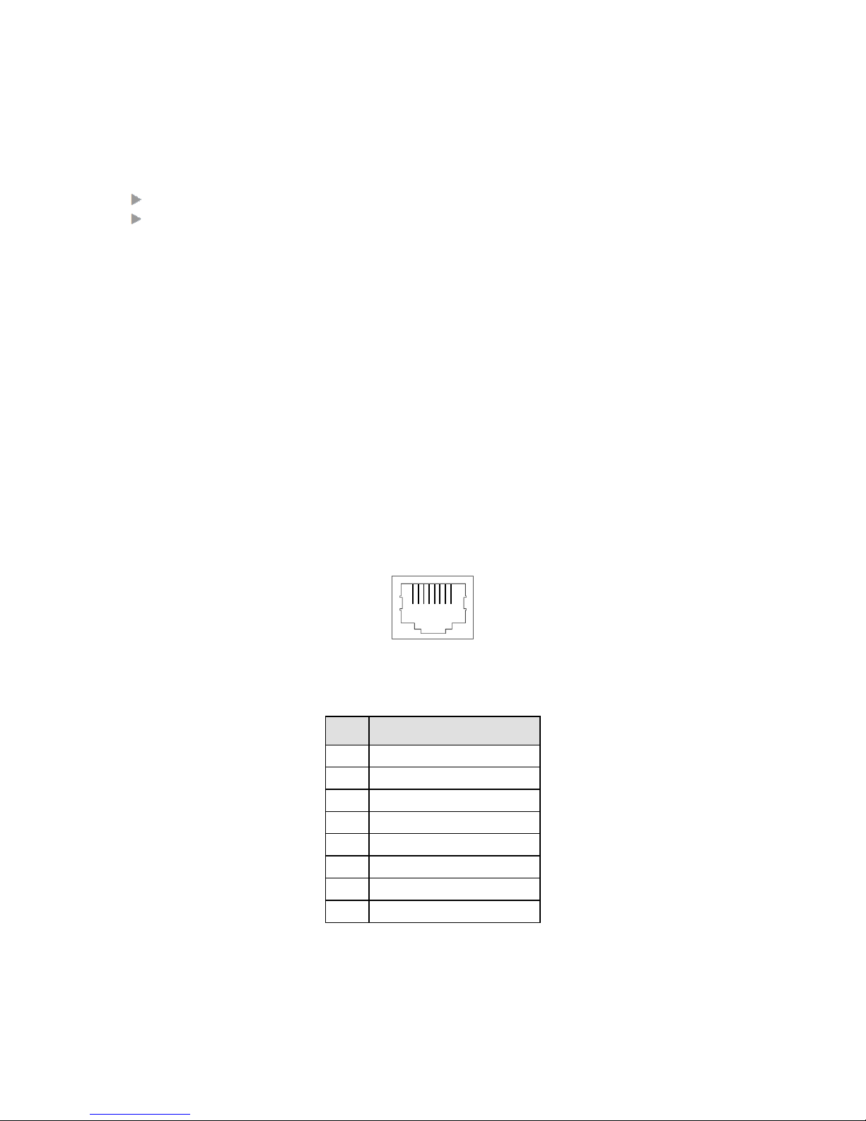
f. DI (=Digital Input) Connector (RJ45)
Two digital inputs (=DI), to detect an open or closed potential free contact, are available via
the DI RJ45 connector on the front panel, see Figure 6. Via these inputs, the NSM can pick up
external events (e.g. opening door …) and raise an appropriate alarm (e.g. ‘door opened’)
with help text (e.g. ‘close the door’) and severity (e.g. major). These alarm properties can be
assigned to these inputs via HiProvision. The normal behavior of the inputs can be config-
ured as ‘no current detected’ or ‘current detected’ via HiProvision as well. Table 4 shows the
pin allocations for the DI connector. A standard Ethernet cable can be used on this connect-
or.
Furthermore, two input LEDs DI1/2 are available, see Table 3. A DI LED is lit when current is
detected on the input.
Figure 9 DI, DO RJ45 Connector
Table 5 DI Pin Allocation
Pin
DI (Input) Description
1
In1a
2
In1b
3
---
4
In2a
5
In2b
6
---
7
---
8
---
Inputs a and b are symmetrical. E.g. input1 (=In1), make a shortcut between pin In1a and
In1b on the input to activate the input àcurrent flows through the input, see figure below;
1 8

14 Installation Dragon PTN Nodes
Release 01 02/2018
Figure 10 Example: Digital Input (=DI): Closed Input
g. DO (=Digital Output) Connector (RJ45)
Two digital output contacts (=DO) are available on the NSM front panel (Figure 6) for output-
ting minor/major alarms. These outputs can be used for example to activate an alarm siren.
These alarms can be configured in HiProvision, see Ref. [1] in Table 1. The operation of these
contacts influences the DO LEDs, see Table 4.
These contacts are change-over contacts on a relay activated by a logical ‘1’. Maximum cur-
rent through such a contact: 1A DC; maximum voltage: 60 VDC. The DO connector in Figure 9
has following pin allocation:
Table 6 DO Pin Allocation
Pin
Contact
Pin Name
DO (Output) Description
Alarm
1
DO1
C1
Out Common 1
Minor Alarms
2
DO1
NC1
Out Normal Closed 1
3
DO1
NO1
Out Normal Open 1
4, 5
---
---
---
---
6
DO2
C2
Out Common 2
Major Alarms
7
DO2
NC2
Out Normal Closed 2
8
DO2
NO2
Out Normal Open 2
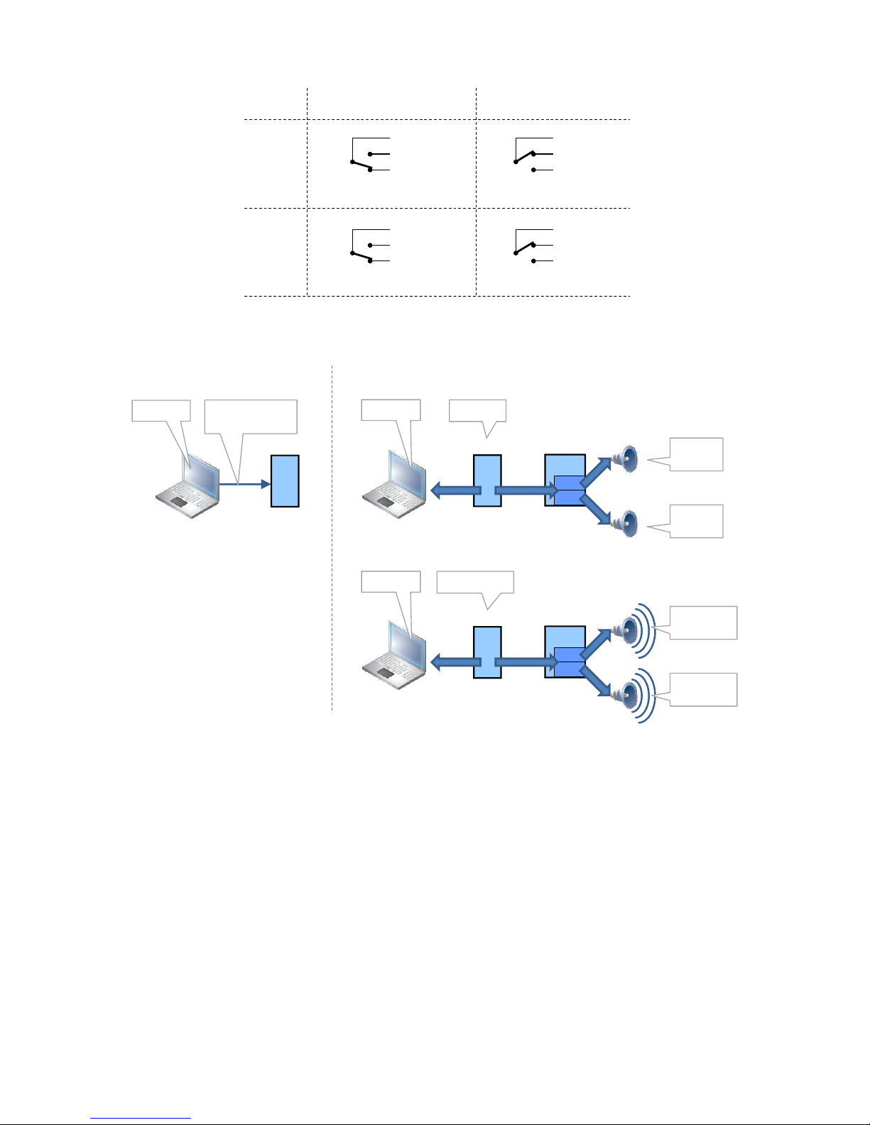
How the DO contacts behave in a normal (no alarm) and an alarm situation can be found in
the figure below:
I/O
1
2
NSM
DI
In1a
In1b
HiProvision:
Expected: Current Detected = YES
Measured: Current Detected = YES
Expected = Measured àno alarm
I/O
1
2
NSM
DI
In1a
In1b
normal:
closed door,
current flows
HiProvision:
Expected: Current Detected = YES
Measured: Current Detected = NO
Expected ≠ Measured àALARM RAISED
alarm:
opened door,
no current
Installation Dragon PTN Nodes 15
Release 01 02/2018
Figure 11 DO Contact Behavior: No Alarm/Alarm
Figure 12 Alarming via Digital Output (=DO) Contacts
NOTE: A ‘normal open output’ contact is created between the ‘C’ and the ‘NO’ pin of that
contact whereas a ‘normal closed output’ contact is created between the ‘C’ and
the ‘NC’ pin of that contact.
NOTE: A standard Ethernet cable can be used on this connector.
2.2.3 PoE (=Power Over Ethernet) (only on NSM-A)
PoE is a technology that allows a Powered Device (=PD, e.g. IP telephones, IP cameras etc.)
to receive power from ‘Power Sourcing Equipment’ (=PSE, e.g. the Dragon PTN node).
Dragon PTN nodes are able to deliver PoE when one (or two) external PoE PSU(s) is (are)
connected to the NSM via the PoE connectors. A possible external PoE PSU and how to con-
nect it can be found in §2.3.2.
DO (DO1)
Minor
No Alarm
(contact activated)
LED DO1: lit green LED DO1: not lit
LED DO2: lit green LED DO2: not lit
DO (DO2)
Major
Alarm
(contact idle)
1 (C1)
RJ45
2 (NC1)
3 (NO1)
1 (C1)
RJ45
2 (NC1)
3 (NO1)
6 (C2)
RJ45
7 (NC2)
8 (NO2)
6 (C2)
RJ45
7 (NC2)
8 (NO2)
CSM
I/O
DO1
No alarm
No alarm
CSM NSM
DO2
Configure
NSM output alarms
HiProvision HiProvision
I/O
DO1
Alarm detection
CSM NSM
DO2
HiProvision
No alarm
Minor alarm
if configured
Major alarm
if configured
Configure Monitor
16 Installation Dragon PTN Nodes
Release 01 02/2018
The PD receives power in parallel to data, over the existing CAT-5 (or higher for more power)
Ethernet infrastructure without it being necessary to make any modifications to it. PoE inte-
grates data and power on the same cable, it keeps the structured cabling safe and does not
interfere with concurrent network operation, see Figure 17.
PoE delivers a minimum of 48V of DC power over shielded/unshielded twisted-pair wiring for
terminals consuming less than 25.5 Watts of power.
Before the power is delivered to a connected device, a protocol measures whether that de-
vice is a PoE device and how much power it needs (power classification). If required, the
necessary power will be delivered by the PSE with a maximum of 40 Watts per port. PoE is
supported on all the electrical RJ45 ports of the 4-GC-LW module. All these ports can deliver
power according to the 802.3af (PoE) and 802.3at (PoE+) standard.
Via HiProvision it is possible to enable/disable PoE per port and to verify which ports in each
node are PoE enabled.
(Future) Power management is supported, i.e. the Dragon PTN node decides in an intelligent
way which PoE ports will get power and which ones will not. There are a lot of possible
scenarios in which power management must tune its delivered power on each port. Some
configuration/status parameters in HiProvision used by power management are:
External PoE PSU power
Available power budget
Power Priority / Port Priority
Power Class (class 0, 1, 2, 3, 4 configured and detected)
Power management also offers PoE diagnostics in HiProvision.
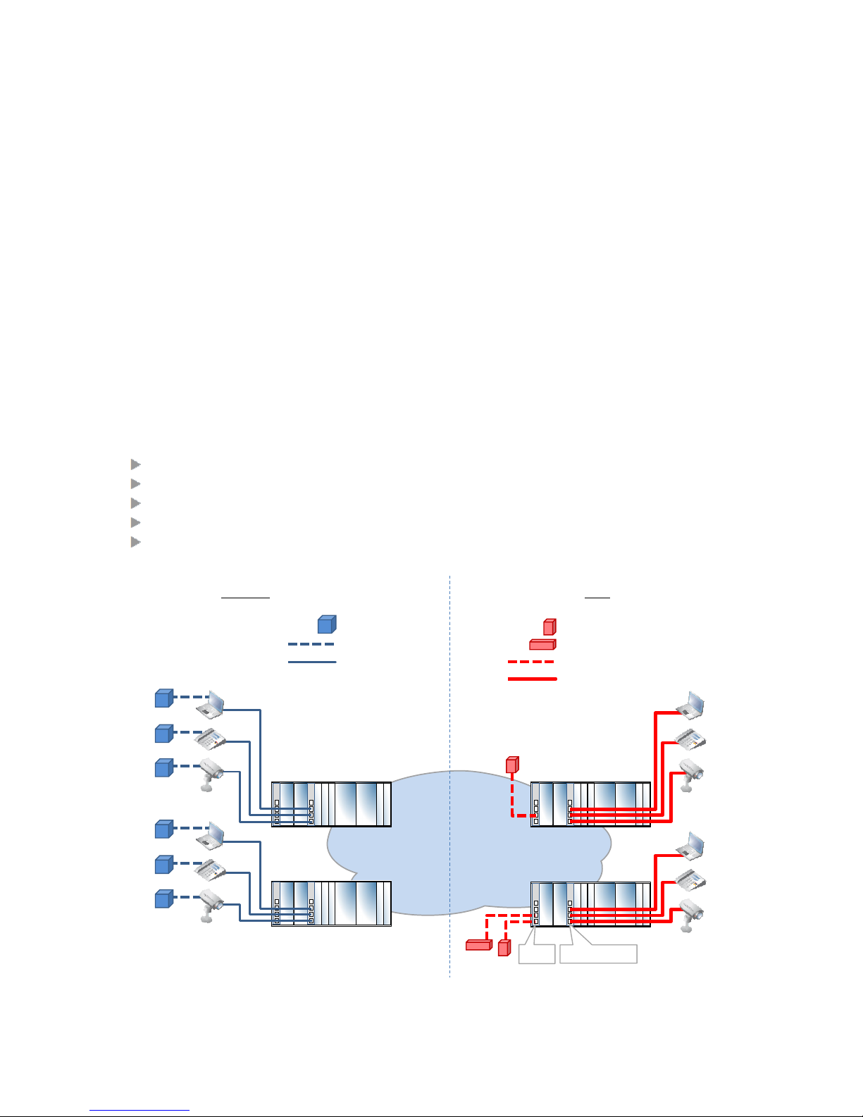
Figure 13 General PoE Example
NSM PSU-1 PSU-2 CSM-1 CSM-2
IFM-1 IFM-2 IFM-3 IFM-4 IFM-5 IFM-6
NSM PSU-1 PSU-2 CSM-1 CSM-2
IFM-1 IFM-2 IFM-3 IFM-4 IFM-5 IFM-6
NSM PSU-1 PSU-2 CSM-1 CSM-2
IFM-1 IFM-2 IFM-3 IFM-4 IFM-5 IFM-6
Dragon PTN
MPLS-TP Network
PoE Power & Data
External PSU AC/DC PoE PSU àNSM
DC/DC PoE PSU àNSM
PowerData only
Power
No PoE PoE
NSM PSU-1 PSU-2 CSM-1 CSM-2
IFM-1 IFM-2 IFM-3 IFM-4 IFM-5 IFM-6
4-GC-LW IFM
NSM

Installation Dragon PTN Nodes 17
Release 01 02/2018
2.3 PSU (=Power Supply Unit)
2.3.1 Node PSUs
PSU1 and/or PSU2 supply the voltage for all the modules in the node.
Three different power supplies are available, one AC PSU, one low voltage and one high
voltage DC PSU. Node XT-2210-A, XT-2209-A and XT-2206-A can be equipped with dual PSUs
for redundancy purposes. These two PSUs in one node can be of the same type or a mix of
different types. If both PSUs are up and running, the load is shared over the two PSUs.
Make sure to tighten the PSU fastening screws after plugging in the PSUs.
The AC power cable has a locking mechanism. Both the DC PSUs and its power cable plug
have unique coding keys (see figures below). A coding key is a physical obstruction in the
PSU connector and cable with Phoenix plug to ensure that:
only a high DC voltage (cable) can be connected to a high voltage DC PSU;
only a low DC voltage (cable) can be connected to a low voltage DC PSU;
Following PSUs and cables are available:
a. AC PSU
PSU ACP-A, 942 234-001: input voltage 100 to 240 VAC ± 10 %;
Power cables with locking mechanism are available for Europe, UK and US, Table 2.
Figure 14 ACP-A PSU with Power Cable
CAUTION: Some parts within the
node can be extremely hot
power cable with
locking mechanism
Fastening screw
Handle

18 Installation Dragon PTN Nodes
Release 01 02/2018
b. DC PSU Low Voltage
PSU DCP-A, 942 234-002: input voltage 18 to 60 VDC;
Power cable (3m) with code keys: 942 256-103;
Figure 15 DCP-A PSU (18-60VDC) / Power Cable / Code Keys
Table 7 DCP-A PSU (18-60VDC) / Power Cable / Code Keys
Pin
PSU Side
Cable Side
+
Code Key
-
Code Key
PE
Code Key
c. DC PSU High Voltage
PSU DCP-B, 942 234-003: input voltage 88 to 300 VDC;
Power cable (3m) with code keys: 942 256-104;
code key
code key
code key
CAUTION: Some parts within the
node can be extremely hot
power cable with
code keys
Fastening screw
Handle

Installation Dragon PTN Nodes 19
Release 01 02/2018
Figure 16 DCP-B PSU (88-300VDC) / Power Cable / Code Keys
Table 8 DCP-B PSU (88-300VDC) / Power Cable / Code Keys
Pin
PSU Side
Cable Side
+
Code Key
-
Code Key
PE
Code Key
Some PSU LEDs (PSI1/2 and PSO1/2) indicate the operation of the PSUs, see Table 3.
The XT-2210-A/XT-2209-A/XT-2206-A node can operate with either one or two power sup-
plies in any of the PSU positions. Any of the PSUs can be mixed in one node. The XT-1104-A
node has one PSU slot available in which any of the PSUs can be used. An empty PSU slot in
the XT-2210-A/XT-2209-A/XT-2206-A node must be covered with a cover plate, see Table 2.
The total output of the power supplies is rated at 175 Watt with 12V output at 65°C. The
total power consumption of the equipped node is the sum of all the individual power
consumptions of each module. Refer to the relevant module manuals for the power
consumption of the CSM and IFMs. The tables below show the specifications of the AC and
DC PSUs.
code keycode key
power cable with
code keys
code key
CAUTION: Some parts within the
node can be extremely hot
Fastening screw
Handle

20 Installation Dragon PTN Nodes
Release 01 02/2018
Table 9 Specifications: ACP-A PSU (100-240VAC± 10%)
Parameter
Condition / Remark
Value
Input
Input voltage range
50-60Hz
100-240VAC ± 10%
Efficiency
At 230VAC and Pout is 220W
At 110VAC and Pout is 220W
> 91%
> 87%
Inrush current max.
Cold start 230V
30A
General
MTBF (MIL-HDBK-217F)
At 25 °C (GB)
> 34 years
Protections
Auto restart
Over temperature, Overcurrent
Input connector
IEC320 on front panel
Table 10 Specifications: DCP-A PSU (18-60VDC)
Parameter
Condition / Remark
Value
Input
Input voltage range
18-60VDC (nominal 24VDC)
Efficiency
At 48VDC and Pout is 220W
At 24VDC and Pout is 220W
> 90%
> 88%
Inrush current max.
Cold start 48VDC
30A
General
MTBF (MIL-HDBK-217F)
At 25 °C (GB)
> 34 years
Protections
Auto restart
Over temperature, Overcurrent
Input connector
PCB side: PC 4/ 3-G-7,62 and BF-PC 4
Cable side: PC 4 HV/ 3-STF-7,62
Table 11 Specifications: DCP-B PSU (88-300VDC)
Parameter
Condition / Remark
Value
Input
Input voltage range
88-300VDC (nominal 230VDC)
Efficiency
At 230VDC and Pout is 220W
At 110VDC and Pout is 220W
> 91%
> 87%
Inrush current max.
Cold start 230V
30A
General
MTBF (MIL-HDBK-217F)
At 25 °C (GB)
> 34 years
Protections
Auto restart
Over temperature, Overcurrent
Input connector
Pcb Side: GMSTB 2.5/3-GF-7.62-1806232
Cable side: GRMSTB 2.5/3-STF-7.62-1805990
2.3.2 PoE PSUs (only on NSM-A)
The NSM-A front panel has 2 PoE connectors to connect 2 external PoE sources or PSUs. One
or two AC/DC (=ACPoE-A) or DC/DC (=DCPoE-A) PSUs, or a mix can be connected to the
NSM.
Two connected PSUs will operate redundantly. Power aggregation is not supported. When
two PSUs are connected, always the lowest power of both PSUs will be taken by HiProvision
to calculate the PoE power.
Other manuals for Dragon PTN
1
This manual suits for next models
4
Table of contents
Other Hirschmann Network Hardware manuals

Popular Network Hardware manuals by other brands

Dell
Dell SonicWALL SuperMassive 9600 Getting started guide

Johnson Controls
Johnson Controls XP-910x Configuration guide

Pogoplug
Pogoplug Pogoplug user manual

S-Access
S-Access ETHERLINK IV Technical description and operations manual

Opengear
Opengear OG-HDBT-Rx user manual

Delta
Delta AHCPU560-EN2 Series Operation manual


 Series user manual")


