IPEX PH232T485Y14 User manual

Doc No: PH232T485Y14-UM-001
USER’S MANUAL
IPEX
(IP Electronix)
16 January 2022
PH232T485Y14
RS-232 to #4 RS-485/RS-422 ISOLATED HUB
www.ipelectronix.com
IPEX (IP Electronix) PH232T485Y14: User’s Manual
Page 2 of 17 Doc No.: PH232T485Y14-UM-001
16 January 2022

www.ipelectronix.com
IPEX (IP Electronix) PH232T485Y14: User’s Manual
Page 3 of 17 Doc No.: PH232T485Y14-UM-001
16 January 2022
CONTENTS
1. INRODUCTION.......................................................................... 4
2. SPECIFICATIONS ....................................................................... 5
3. PACKAGE CHECKLIST................................................................. 6
4. TOP VIEW................................................................................. 7
5. BOTTOM VIEW ......................................................................... 7
6. FRONT VIEW............................................................................. 7
7. BACK VIEW............................................................................... 7
8. PORT SETTINGS ........................................................................ 8
9. RS-232 SERIAL PORT PIN CONFIGURATION................................ 9
10. RS-485/RS-422 SERIAL PORT PIN CONFIGURATION ................. 9
11. PH232T485Y14 CONNECTION DIAGRAM............................... 10
12. RS-232 CONNECTING METHODS ........................................... 12
13. RS-485 CONNECTING METHODS ........................................... 15
14. RS-422 CONNECTING METHODS ........................................... 16
15. GUARANTEE......................................................................... 17
16. TECHNICAL SUPPORT ........................................................... 17

www.ipelectronix.com
IPEX (IP Electronix) PH232T485Y14: User’s Manual
Page 4 of 17 Doc No.: PH232T485Y14-UM-001
16 January 2022
1. INRODUCTION
IPEX PH232T485Y14is a Bi-Directional RS-232 to 4 RS-485/RS-422 HUB that provides #4 RS-485/RS-
422 ports from one single RS-232 port that converts RxD & TxD signals of RS-232 standard to
differential (Data+ & Data-) signals of RS-485 standard and (RX+, RX- & TX+, TX-) signals of RS-422
standard at a same time. It works with Baud-Rate from 300bps to 230400bps. Using this device, you
can connect a RS-232 line, to 4 different devices which have RS-485 or RS-422 ports.
Since RS-485 is a Half-Duplex standard, switching between Transmit and Receive is done
automatically and further signals (such as RTS) are not required. PH232T485Y14supports Point-to-
Point and Point-to-Multi Point Party Line network topologies.
There are 3kV Optical and Electrical insulations have between RS-232/TTL UART and RS-485/422
sides, thus using this device in the RS-485/RS-422 line, can be very effective in eliminating electrically
and electromagnetically noises.
Protection against Surge, ESD and EMI is considered in its design, so, PH232T485Y14is good for
industrial usage and is useful for Industrial Automation, Telecommunications, SCADA Systems, DCS
Systems and …

www.ipelectronix.com
IPEX (IP Electronix) PH232T485Y14: User’s Manual
Page 5 of 17 Doc No.: PH232T485Y14-UM-001
16 January 2022
2. SPECIFICATIONS
RS-232/TTL UART to #4 RS-485/422 Bi-Directional Isolated HUB;
Number of Ports: #1 RS-232 to #4 RS-485/422 Bi-Directional Repeater;
Serial Standard: Meets or Exceeds the Requirements of TIA/EIA-232-F and ITU v.28 Standards;
RS-232 Signal (Full Flow Control Support): TxD, RxD, DTR, RTS, DSR, CTS, GND;
RS-232 Parity: Even, Odd, None, Mark and Space;
Standard TTL TxD and RxD Signals, suitable for directly connect to a Microcontroller
Serial Standard: Meets or Exceeds the Requirements of RS-485/422 Standards;
RS-485 Signal: Data+, Data-, GND;
RS-422 Signal: TX+, TX-, RX+, RX-, GND;
RS-485/422 Parity: Even, Odd, None, Mark and Space;
Maximum Communication Distance: 2400m (1200m each side);
Loading: RS-485 and RS-422 Side up to 32 Nodes are supported;
Fully Plug & Play;
Wide Range Power Supply: +8V to +48V DC;
Serial Transmission Speed up to 230.4 kbps;
Power (Green) LED Indicator;
Transmit (Blue) and Receive (Yellow) LED Indicator;
Isolation Protection: 3kV Instantaneous, 500V DC Continuous;
Surge Protection: Embedded 1500W Surge Protection;
Magnetic Isolation: 1.5 kV Built-in;
ESD Protection: Exceeds ±15 kV Using Human-Body Model (HBM);
Dimensions: 218mm x 122mm x 30mm (8.58in x 4.80in x 1.18 in);
Operating Temperature: -10°C to +70°C (+14°F to +158°F);
1 Year Guarantee and 5 Years Support.
www.ipelectronix.com
IPEX (IP Electronix) PH232T485Y14: User’s Manual
Page 6 of 17 Doc No.: PH232T485Y14-UM-001
16 January 2022
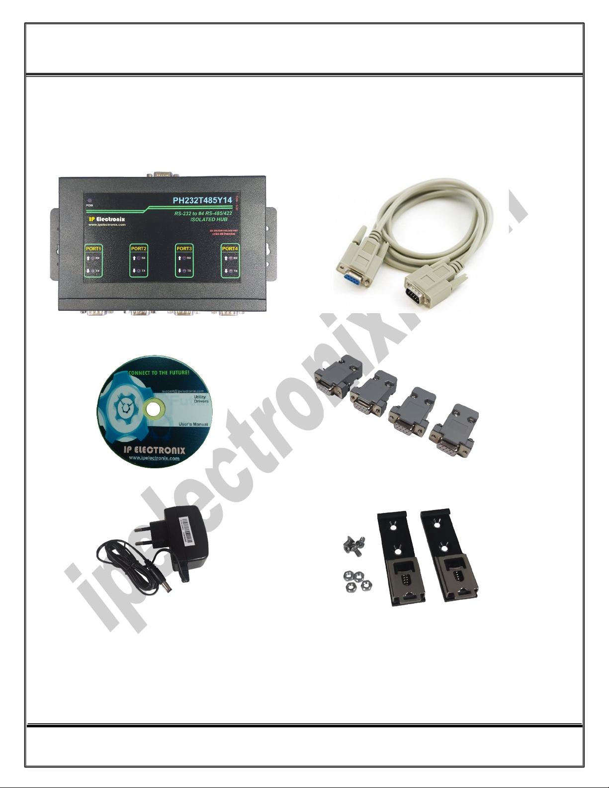
3. PACKAGE CHECKLIST
Before installing the PH232T485Y14, verify that the package contains the following items:
1) #1 PH232T485Y14 2) #1 RS-22 Male to Female Cable
3) #1 Document and Driver CD-ROM 4) #4 DB9 Female Connector
5) #1 220V AC to 12V DC Adaptor 6) #2 Din Rail Brackets with the corresponding screws
NOTE: Notify your sales representative if any of the above items is missing or damaged.

www.ipelectronix.com
IPEX (IP Electronix) PH232T485Y14: User’s Manual
Page 7 of 17 Doc No.: PH232T485Y14-UM-001
16 January 2022
4. TOP VIEW
5. BOTTOM VIEW
6. FRONT VIEW
7. BACK VIEW
www.ipelectronix.com
IPEX (IP Electronix) PH232T485Y14: User’s Manual
Page 8 of 17 Doc No.: PH232T485Y14-UM-001
16 January 2022
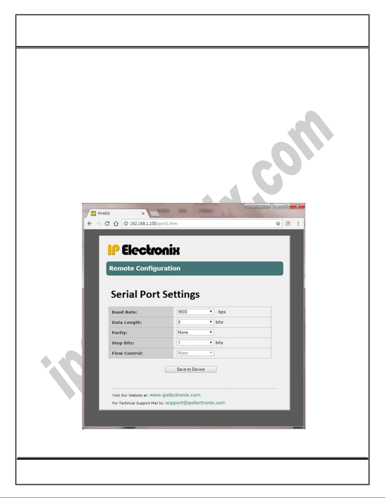
8. PORT SETTINGS
Connect PH232T485Y14 to your PC or Laptop by means of Ethernet RJ-45 port, the default IP of the
device is 192.168.1.100 and the default subnet mask is 255.255.255.0.
Make sure the PC IP and is in the PH232T485Y14 IP Range and the PC subnet mask is same as
PH232T485Y14.
Now open a web browser like Google Chrome or Firefox on your PC and type the device IP on the
address bar of the web browser, then you can see the device port settings page as shown below and
you can change the settings to what you want and then press save button to save them and close the
browser.
www.ipelectronix.com
IPEX (IP Electronix) PH232T485Y14: User’s Manual
Page 9 of 17 Doc No.: PH232T485Y14-UM-001
16 January 2022
9. RS-232 SERIAL PORT PIN CONFIGURATION
1
2
3
4
5
6
7
8
9
PIN
DCD
RxD
TxD
DTR
GND
DSR
RTS
CTS
RI
NAME
OUTPUT
INPUT
OUTPUT
OUTPUT
OUTPUT
INPUT
INPUT
OUTPUT
GROUND
TYPE
Data Communication Equipment (DCE)
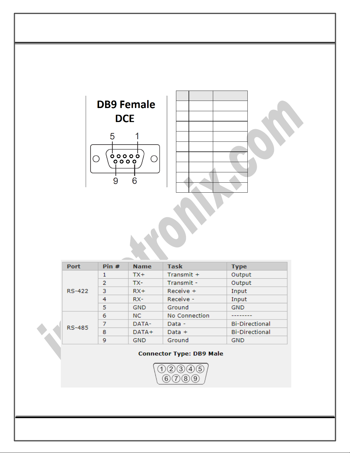
10. RS-485/RS-422 SERIAL PORT PIN CONFIGURATION
www.ipelectronix.com
IPEX (IP Electronix) PH232T485Y14: User’s Manual
Page 10 of 17 Doc No.: PH232T485Y14-UM-001
16 January 2022
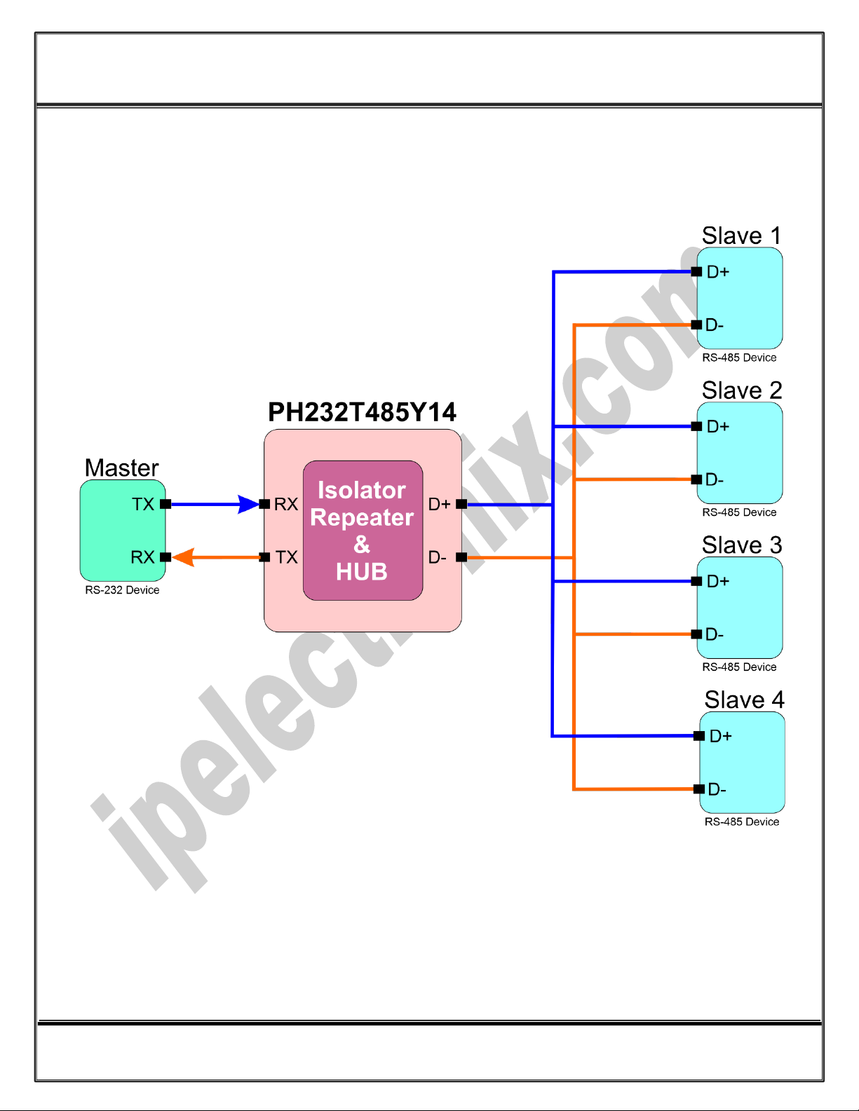
11. PH232T485Y14 CONNECTION DIAGRAM
-PH232T485Y14 in RS-485 Mode
Table of contents
Other IPEX Network Hardware manuals


Popular Network Hardware manuals by other brands

Matrix Switch Corporation
Matrix Switch Corporation MSC-HD161DEL product manual

B&B Electronics
B&B Electronics ZXT9-IO-222R2 product manual

Yudor
Yudor YDS-16 user manual

D-Link
D-Link ShareCenter DNS-320L datasheet

Samsung
Samsung ES1642dc Hardware user manual

Honeywell Home
Honeywell Home LTEM-PV Installation and setup guide


