Hissmekano AB Reprovägen 7 SE-183 77 Täby Tel: +46-(0)8-586 272 00 Fax: +46-(0)8-732 51 26 E-post: info@hissmekano.se
4. Connections of the contacts
LI-25-30 and LI25-R have door contacts, one for each door and a lock
contact. Below is the wiring diagram. LI-25-30 has KO-30 & LI-25-R has
KO-26 door contact.
Cables are attached between contact blades on locking contact and
door contacts. Ground 9is connected with cable lug.Rear contact 1, 2
is switched on if necessary.
5. Magnet Switch (Valid only to locks with magnet
contact)
LI-25-30-M-H, freight lock with magnet switch for hidden Contact
230VAC 0.4A to prevent tampering/manupulation.
Magnet contact is just for monitoring and neither to put into door or
security circuit. Mandatory contact bridge with magnet included in
kit or ordered seperately Art.no:2400126-M.
Figure 8 Mounting of the roller
REQUIREMENTS
The lock should not be lubricated. The European Standard EN 81-20 requires
a minimum lactching bolt engagement of 7mm before the lock contact closes.
RECOMMENDATIONS
we recommend to adjust the lactching bolt engagement to 15mm.
REGULATIONS
LI-25-30 & LI-25-R locks meets the requirements of EN81-20 with additional
hidden door contact. Installation is carried out according to European stan-
dards EN 81-20
CERTIFICATE
EU Certied, 20-GOT-LD-002, Kiwa Inspecta AB. Notied body No: 0409
TECHNICAL SPECIFICATIONS
Lock/Auxilary contact:
Voltage: 230VAC / 200VDC
Current: 2A AC/DC
INSTALLATION MANUAL 2 OF 2
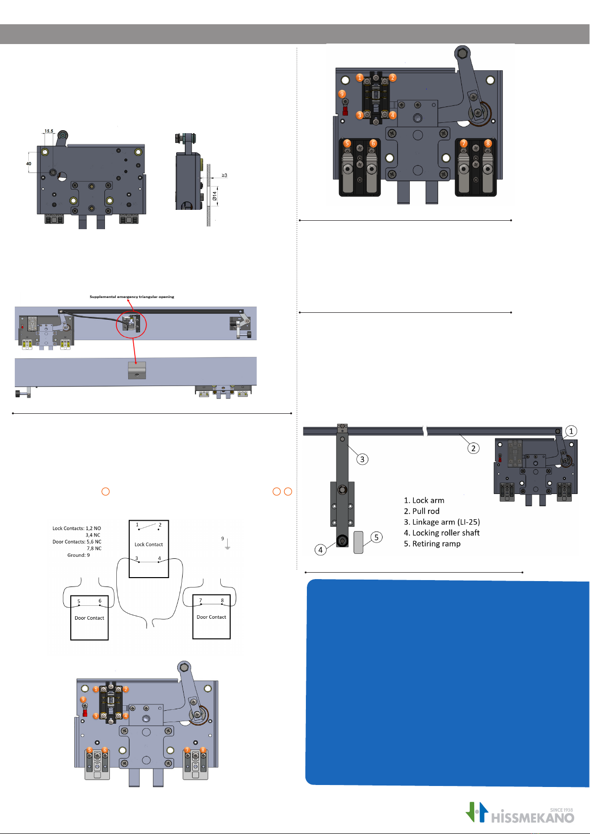
6. Mounting and adjustment of the roller
The pull rod 2 (1250mm- can be ordered in dierent lengths)
is mounted with lock arm 1. Linkage arm 3is mounted to
other end of pullrod. Locking roller shaft 4is mounted on lin-
kage arm and tightened. The roller should be centered over
the retiring ramp 5. The linkage arm is nally adjusted so that
the roller is about 2 mm from the retiring ramp when the ramp
is retracted.
3. Emergency opening function
i. Valid only to locks with triangle opening
Holes are drilled in the door frame for the emergency opening function
as shown in the gure below. The hole should be at least 14mm in dia-
meter and the triangle should be recessed at least 3mm from the front
to meet the EN81-20 standard.
Figure 4 (i) Emergency unlocking
Figure 7 Picture showing connection numbers (LI-25-R)
Figure 5 connections for door and lock contacts
Figure 6 Picture showing connection numbers (LI-25-30)
ii. Emergency opening function (Supplemental)
Hole of 60mm diameter is drilled in the door frame to install supple-
mental emergency opening function. Bevel gear, lock and triagular
opening are connected with bowden cables as shown in Fig.4 (ii)
Figure 4 (ii) Supplemental emergency triangular opening


