Hisun HS800 User manual

Forth version , May, 2014
Published by Chongqing
Huansong Industries
(Group) Co., Ltd and
Hisun Motors Corp USA.
Chongqing Huansong
Industries (Group)
Co., Ltd and Hisun
Motors Corp USA
holds the copy right.
No publishing and
reprinting without
permission
READ THIS
MANUAL
CAREFULLY
For questions regarding
this UTV, please
contact HISUN at:
(877) 838-6188
www.hisunmotors.com
REV. 06051401
SERVICE
MANUAL
HS800

Foreword
Brief introduction to maintenance handbook of
HS800UTV
The handbook is edited by Technical Center of Chongqing Huansong Industries (Group)
Co., Ltd., and is supplied to dealers and technicians as a docu ent of technique.
This anual gives ethods to check, aintain and repair utility terrain vehicles (UTV’s),
and supplies so e relevant techniques and perfor ance data. So e
techniques and ethods inside ay be used to check, aintain and repair other odels
of UTV, although it is ainly for the HS800UTV.
Please read the handbook through and fully understand it; otherwise, any i proper
repairing could bring you proble s, and or an accident ay occur.
Proper use and aintenance can guarantee the UTV being driven safely, reduce its
alfunctions, and help the vehicle re ain at its best perfor ance level.
The standards, procedures and specifications entioned in this anual are based on
the sa ple in design, and they are subject to changes according to the product’s
i prove ent without prior notice.
Third version , May, 2014
Published by Chongqing Huansong Industries (Group) Co., Ltd.
Chongqing Huansong Industries (Group) Co., Ltd holds the copy right.
No publishing and reprinting without per ission.
INDEX
Chapter 2
Specifications
Chapter 3
Periodic
Maintenance and
Adjustments
Chapter 4
Engine
Chapter
Chassis
Chapter 6
Electrical
Chapter 7
Engine
Management
System
Chapter 8
Troubleshooting
???
Wiring
Diagrams
Index
1.
2.
3.
Chapter 1
General

INDEX

INDEX
Chapter 1 General Information
Warnings, Cautions, Notes
Description, Location
Identification Code, Frame
Number, Engine Number
Safety
Handling Gasoline, cleaning parts
Warning Labels, Serial Numbers,
Fasteners, orque specs, Self
Locking fasteners
Washers, Cotter pins, Snap rings,
and E-clips
Shop Supplies, Lubricants, Engine
Oils
Greases, Brake Fluid, Coolant
Cleaners, Degreasers and
Solvents
Basic ools
Precision Measuring ools
Compression Gauge, Multimeter
Basic Service Methods
Storage
Chapter 2 Specifications
Conversion ables
General Specs
Engine Specs
Suspension Specs
Electrical Specs
Engine orques
Chassis orques
General orques
Lubrications
Chapter 3 Periodic Maintenance
and Adjustment
Maintenance Schedule
Valve Adjustment
Compression est
Engine Oil
Air Filter
Coolant Level
V-Belt
1-3
1-4
1-5
1-6
1-7
1-8
1-9
1-10
1-11
1-12
1-12
1-19
1-25
1-27
1-28
2-3
2-4
2-7
2-13
2-15
2-17
2-20
2-22
2-23
3-3
3-5
3-6
3-7
3-8
3-10
3-13
Spark Arrester
Brake Pedal
Brake Pads
Shift Lever Adjustment
Final Gear Oil
Steering System
Shock absorbers
ires
Headlight Adjustment
Chapter 4 Engine
Special notes
hrottle and Intake Manifold
Removal
Cylinder Head Cover and
Cylinder Head
Rocker Arms and Camshaft
Valves and Valve springs
Cylinder and Piston
Left Crankcase Cover and A.C.
Magneto
Starter motor and Oil Filter
Primary and Secondary Sheaves
Crankcase Cover and Oil Pump
Crankcase and Middle Driven
Shaft
Output Shaft
Gearcase Shift Lever and Oil
Pump
Gearcase ransmission
Chapter Chassis
Steering Assembly
Disc Brake components
Front Brake Caliper
Rear Brake Caliper
Parking Brake Caliper
Footrest
Front Wheel and ire
Rear Wheel and ire
Cv Axle, Front Axle
Front Bridge
Cv Axle, Rear Axle
Rear Bridge Reeducer
3-13
3-14
3-15
3-16
3-17
3-18
3-19
3-19
3-20
4-3
4-4
4-5
4-8
4-10
4-14
4-17
4-19
4-21
4-24
4-27
4-30
4-33
4-35
5-3
5-9
5-11
5-15
5-16
5-20
5-23
5-24
5-27
5-28
5-32
5-33

INDEX
Gear Shift Assembly
Front Swing Arm
Front Suspension
Rear Anti-roll Bar
Rear Swing Arm
Radiator and Oil Cooler
Water Pump
Seat
Fuel ank
Chapter 6 Electrical
Electrical Basics
Charging a Lead Acid Battery
Charging a Maintenance Free
Battery
Checking the Fuses
Electrical Components
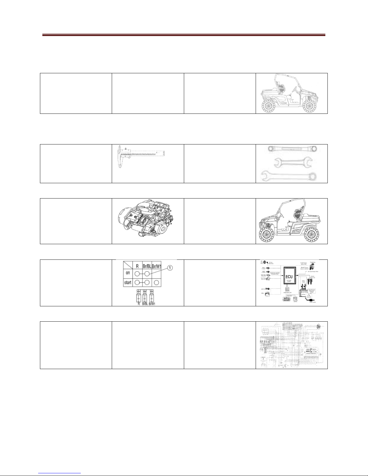
Inspection of the Main Switch
Component Locations
roubleshoot (NO SPARK)
roubleshoot (Starter Motor
Failure)
Starter Motor Removal
roubleshoot (Battery is not
Charging)
Chapter 7 Engine Management
System
EMS Introduction, Components
Layout
ECU
Multec 3.5 Injectors
hrottle Body Assembly
Engine Coolant emp Sensor,
Oxygen Sensor
Fuel Pump Module
Fault Codes
5-36
5-39
5-40
5-43
5-44
5-47
5-51
5-56
5-59
6-3
6-4
6-6
6-7
6-8
6-10
6-11
6-12
6-15
6-16
6-17
7-3
7-4
7-4
7-5
7-7
7-8
7-9
7-12
Chapter 8 Troubleshoot
roubleshoot Basics
Principles and Requirements
Special Faults
Flooded Engine
Engine will not start
Spark est
Poor Engine Performance
Fuel System
Engine Smoke
Compression
Engine Lubrication
Cylinder Leak Down est
Electrical esting
est Equipment
Brake System
Headlight/ aillight
Lighting System
Brake Light
Reverse Indicator
Coolant emp Warning Light
4 Wheel drive Switch
Radiator Fan Motor
2/4WD Switch, Rear Differential
Fuel System, Electrical System
Starter Motor, Gear Shifting
8-3
8-4
8-4
8-6
8-6
8-7
8-8
8-12
8-13
8-14
8-16
8-17
8-20
8-22
8-27
8-30
8-31
8-32
8-36
8-37
8-39
8-42
8-44
8-45
8-46
General Information
1-1
Warnings, Cautions, Notes
Description, Location
Identification Code, Frame
Number, Engine Number
Safety
Handling Gasoline, cleaning
parts
Warning Labels, Serial Numbers,
Fasteners, orque specs, Self
Locking fasteners
Washers, Cotter pins, Snap
rings and E-clips
1-3
1-4
1-5
1-6
1-7
1-8
1-9
Shop Supplies, Lubricants,
Engine Oils
Greases, Brake Fluid, Coolant
Cleaners, Degreasers and
Solvents
Basic ools
Precision Measuring ools
Compression Gauge,
Multimeter
Basic Service Methods
Storage
1-10
1-11
1-12
1-12
1-19
1-25
1-27
1-33

General Information
1-2

General Information
1-3
This manual provides complete information on maintenance, tune-up, repair and
overhaul. Hundreds of photographs and illustrations created during the complete
disassembly of Utility Terrain Vehicles (UTV) guide the reader through every job.
ll procedures are in step by step format and designed for the reader who may
be working on the UTV for the first time.
Warnings, Cautions and Notes
The terms Warning, Caution and Note have specific meanings in this manual.
Warning
Emphasizes areas where injury or even death could result from
negligence.
Caution
Emphasizes areas where equipment damage could result.
Disregarding a Caution could cause permanent permanent
Mechanical damage, although injury is unlikely.
Note
Provides additional information to make a step or procedure easier
or clearer. Disregarding a Note could cause inconvenience, but
would not cause equipment damage or injury.

General Information
1-4
Description
1. Headlights/Front turning lights/
Position lights
2. Front shock absorber spring
preload djusting ring
3. Rear Brake Fluid Reservoir
4. Parking Brake Lever
5. Driver Seat
6. Battery
7. Fuses
8. Left shoulder protection plate
9. Driver’s seat belt
10. ir Filter case (Engine and ir
intake duct)
11. Cargo Bed
12. Tail light / Rear turning lights
13. Spark arrester
14. Rear Shock absorber assembly
adjusting ring
15. V-belt case
16. Passenger seat belt
17. Right shoulder protection plate
18. Spark plug
19. Oil filter
20. Fuel cap
21. Passenger seat
22. Rear view mirror
23. Coolant reservoir
24. Radiator cap
25. Steering wheel
26. Light switch
27. Main switch
28. On-Command four-wheel-drive
and differential lock switches
29. Multi-function Display
30. uxiliary DC jack
31. Brake pedal
32. ccelerator pedal
33. Drive select lever
34. Passenger handrail
Note:
The vehicle you have purchased
may differ slightly from those in the
figures of this manual.
General Information
1-5
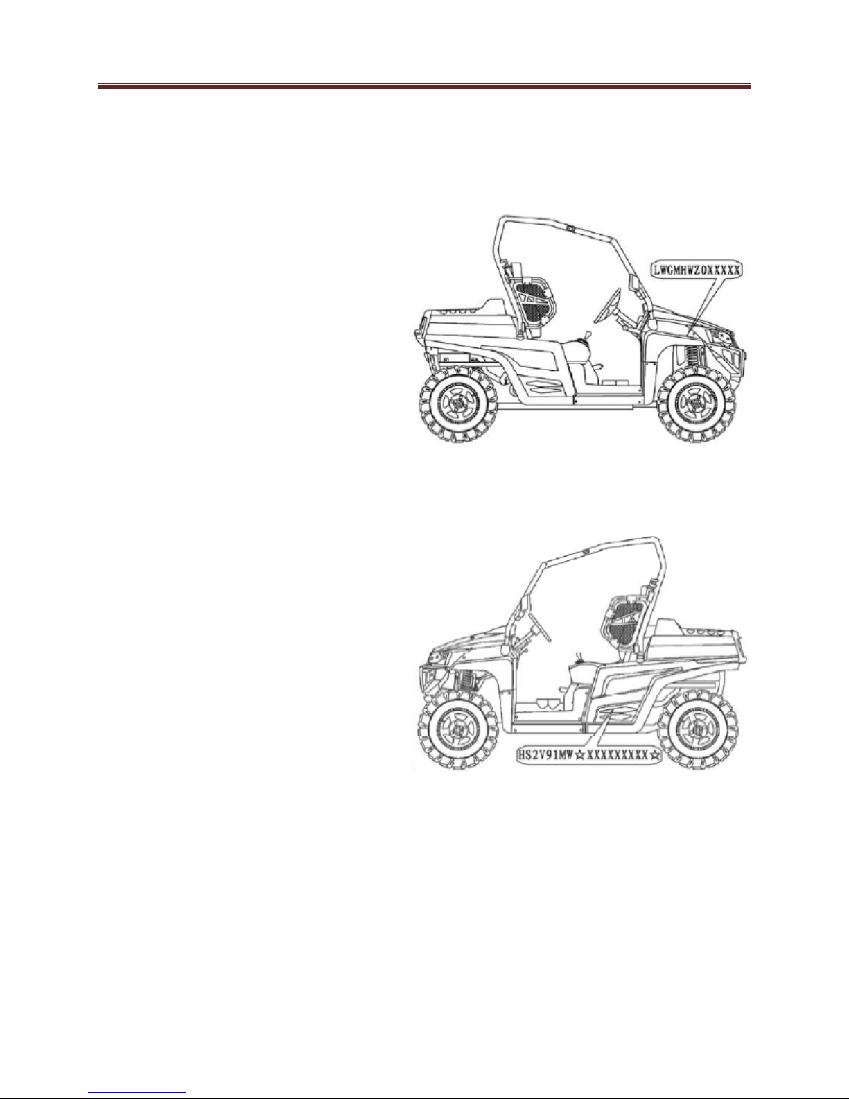
Identification Code
Frame No.
Frame No. is stamped on the right side
of the main frame.
Engine No.
Engine No. is stamped on the right side
of the engine.

General Information
1-6
Vehicle Identification Number
LWG MH WZ 44 E 123456
LWG Manufacturer
MD UTV below 750 cc
MH UTV above 750 cc
SD TV below 750 cc
SH TV above 750 cc
SZ 400 cc
TZ 500 cc
YZ 700 cc
WZ 800 cc
44 DOT Check Digits
2010 Model Year
B 2011 Model year
C 2012 Model Year
D 2013 Model Year
E 2014 Model Year
Manufacturing Plant
B Manufacturing Plant B
123456 Sequential Serial Number

General Information
1-7
Safety
Professional mechanics can work for
many years and never sustain a serious
injury or mishap. Follow these
guidelines and practice common sense
to safely service the utility terrain
vehicle.
1. Do not operate the utv in an
enclosed area. The exhaust
gasses contain carbon monoxide,
which is an odorless, colorless
and tasteless poisonous gas.
Carbon monoxide levels build
quickly in small confined areas
and can cause unconsciousness
and death in a short time. Make
sure to properly ventilate the
work area operate the UTV
outside.
2. Never use gasoline or any
extremely flammable liquid to
clean parts. Refer to cleaning
parts and handling gasoline
safely in this section.
3. Never smoke or use a torch in
the vicinity of flammable liquids,
such as gasoline or cleaning
solvents.
4. If welding or brazing on the UTV
move the fuel tank to a safe
distance, at least 50ft away.
5. Use the correct type and size
tools to avoid damaging
fasteners.
6. Keep tools clean and in good
condition. Replace or repair worn
or damaged equipment.
7. When loosening a tight fastener,
be guided by what would happen
if the tool slips.
8. When replacing fasteners, make
sure the new fasteners are the
same size and strength as the
original ones.
9. Keep your work area clean and
organized.
10. Wear eye protection anytime the
safety of the eyes is in question.
This includes procedures that
involve drilling, grinding,
hammering, use of compressed
air, and chemicals.
11. Wear the correct clothing for the
job. Tie up or cover long hair so it
does not get caught in moving
equipment.
12. Do not carry sharp tools in
clothing.
13. lways have an approved fire
extinguisher available. Make sure
it is rated for gasoline (class B)
and electrical (class C) fires.
14. Do not use compressed air to
clean clothing, the UTV, or the
work area. Debris may be blown
into the eyes or skin. Never direct
compressed air at anyone. Do
not allow children to use or play
with any compressed air
equipment.
15. When using compressed air to
dry parts, hold the part so it does
not rotate. Do not allow the force
of the air to spin the part. The air
jet is capable of rotating parts at
extreme speed and the part may
disintegrate or become damaged
possibly causing injury.
16. Do not inhale the dust created by
brake pad and clutch wear.
These particles may contain
asbestos. Some types of
insulating materials and gaskets
may also contain asbestos.
Inhaling asbestos particles is
hazardous to your health.

General Information
1-8
Handling Gasoline
safely
Gasoline is a volatile flammable liquid
and is one of the most dangerous items
in the shop. Because gas is used so
often, many people forget about the
hazards associated with its use. Gas
should only be used for fuel in a
gasoline internal combustion engine.
Keep in mind when working on the UTV
that gasoline is always present in the
fuel tank, fuel lines and carburetor. To
avoid an accident when working around
a fuel system, carefully observe the
following precautions.
1. Never use gas to clean parts.
Refer to cleaning parts in this
section.
2. When working on the fuel
system, work outside or in a well
ventilated area.
3. Do not add fuel to the fuel tank or
service the fuel system while the
UTV is near open flames, sparks
or where someone is smoking.
Gasoline vapor is heavier than air
and it collects in low areas, and is
more easily ignited than liquid
gasoline.
4. llow the engine to cool
completely before working on any
fuel system component.
5. Do not store gasoline in glass
containers. If the glass breaks, a
serious explosion or fire may
occur.
6. Immediately wipe up spilled gas
with rags. Store the rags in a
metal container with a lid until
they can be properly disposed of,
or washed.
7. Do not pour water onto a
gasoline fire. Water spreads the
fire and makes it more difficult to
put out. Use a class B, BC or
BC fire extinguisher to
extinguish the fire.
8. lways turn off the engine before
refueling. Do not spill fuel onto
the engine or exhaust system. Do
not overfill the fuel tank. Leave an
air space at the top of the tank to
allow room for the fuel to expand
due to temperature fluctuations.
Cleaning Parts
Cleaning parts is one of the more
tedious and difficult service jobs
performed in the home garage. Many
types of chemical cleaners and solvents
are available for shop use. Most are
poisonous and extremely flammable. To
prevent chemical exposure, vapor
buildup, fire and serious injury, observe
each product warning label and note the
following.
1. Read and observe the entire
product label before using any
chemical. lways know what type
of chemical is being used and
whether it is poisonous and or
flammable.
2. Do not use more than one type of
cleaning solvent at a time. If
mixing chemicals is required,
measure the proper amounts
according to the manufacturer.
3. Work in a well ventilated area.
4. Wear chemical resistant gloves.
5. Wear safety glasses
6. Wash hands and arms thoroughly
after cleaning parts.
7. Keep chemical products away
from children and pets.
8. Wear a vapor respirator if the
instructions call for it.

General Information
1-9
9. Thoroughly clean all oil, grease
and cleaner residue from any part
that must be heated.
10. Use a nylon brush when cleaning
parts. Metal brushes may cause
a spark.
11. When using a parts washer, only
use the solvent recommended by
the manufacturer. Make sure the
parts washer is equipped with a
metal lid that can lower in case of
fire.
Warning Labels
Most manufacturers attach information
and warning labels to the UTV. These
labels contain instructions that are
important to safety when operating,
servicing, transporting and storing the
UTV. Refer to the owner’s manual for
the description and location of labels.
Order replacement labels from the
manufacturer if they are missing or
damaged.
Serial Numbers
Serial and identification numbers are
stamped on various locations on the
frame, engine and carburetor body.
Record these numbers in the quick
reference data section in the front of the
manual. Have these numbers available
when ordering parts.
Fasteners
Proper fastener selection and
installation is important to ensure the
UTV operates as designed and can be
serviced efficiently. The choice of
original equipment fasteners is not
arrived at by chance. Make sure
replacement fasteners meet all the
same requirements as the originals.
Many screws, bolts and studs are
combined with nuts to secure particular
components. Marking will indicate the
strength or hardness. Manufacturers
specify the internal diameter and thread
pitch. The measurement across two flats
on a nut or bolt indicates the wrench
size.
Warning
Do not install fasteners with a
strength classification lower than
what was originally installed by the
manufacturer. Doing so may cause
equipment failure and or damage.
Torque Specifications
The material used in the manufacturing
of the UTV may be subjected to uneven
stresses if the fasteners of the various
subassemblies are not installed and
tightened correctly. Fasteners that are
improperly installed or work loose can
cause extensive damage. It is essential
to use an accurate torque wrench as
described in this chapter.
Self-Locking Fasteners
Several types of bolts, screws and nuts
incorporate a system that creates
interference between the two fasteners.
Interference is achieved in various
ways. The most common types are the
nylon insert nut and a dry adhesive
coating on the threads of a bolt. Self-
locking fasteners offer greater holding
strength than standard fasteners, which
improves their resistance to vibration. ll
self-locking fasteners cannot be reused.
The materials used to from the lock
General Information
1-10
become distorted after the initial
installation and removal. Discard and
replace self-locking fasteners after
removing them. Do not replace self-
locking fasteners with standard
fasteners.
Washers
The two basic types of washers are flat
washers and lock washers. Flat washers
are simple discs with a hole to fit a
screw or bolt. Lock washers are used to
prevent a fastener from working loose.
Washers can be used as spacers and
seals, or can help distribute fastener
load and prevent the fastener from
damaging the component. s with
fasteners, when replacing washers
make sure the replacement washers are
of the same design and quality.
Cotter Pins
cotter pin is a split metal pin inserted
into a hole or slot to prevent a fastener
from loosening. In certain applications,
such as the rear axle on an UTV or
motorcycle, the fastener must be
secured in this way. For these
applications, a cotter pin and castellated
(slotted) nut is used. To use a cotter pin,
first make sure the diameter is correct
for the hole in the fastener. fter
correctly tightening the fastener and
aligning the holes, insert the cotter pin
through the hole and bend the ends
over the fastener, Unless instructed to
do so, never loosen a tightened fastener
to align the holes. If the holes do not
align, tighten the fastener enough to
achieve alignment. Cotter pins are
available in various diameters and
lengths. Measure the length from the
bottom of the head to the tip of the
shortest pin.
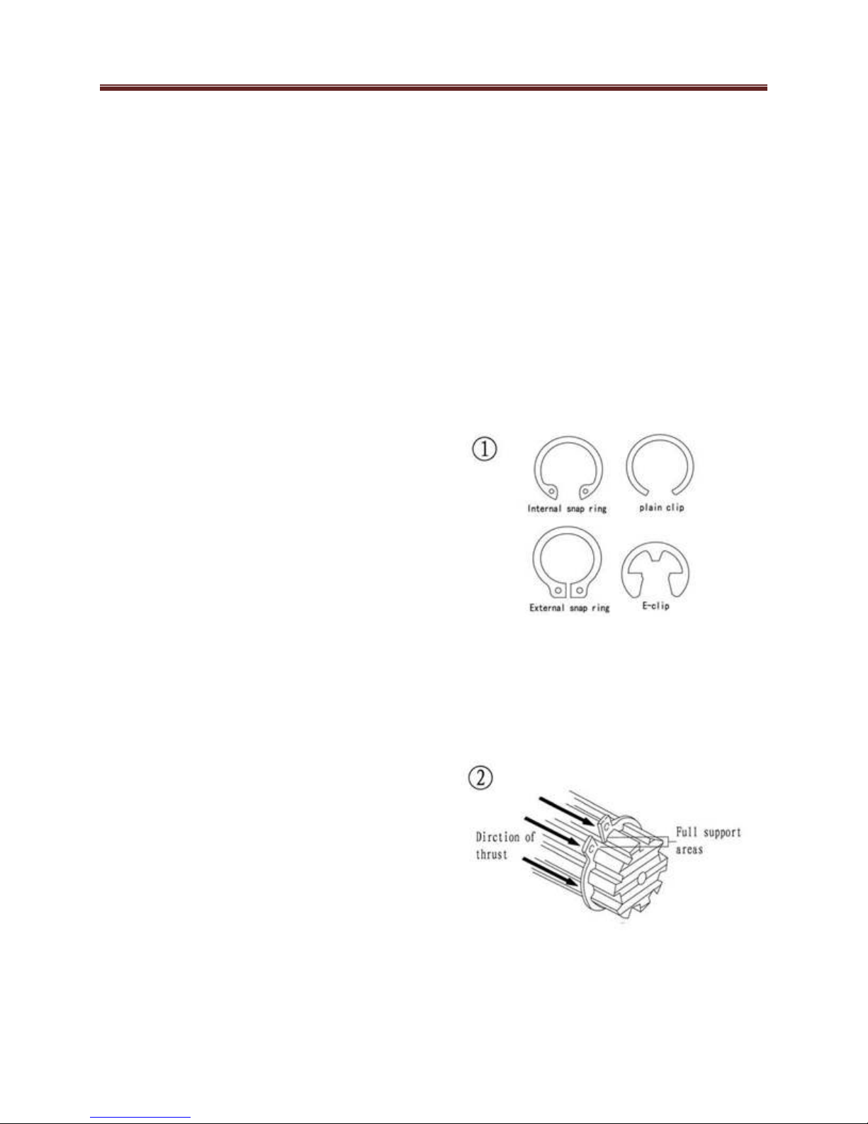
Snap Rings and E-clips
Snap rings (Figure 1) are circular-
shaped metal retaining clips. External
type snap rings are used to retain items
on shafts. Internal type snap rings
secure parts within housing bores. In
some applications, in addition to
securing the component(s), snap rings
of varying thicknesses also determine
endplay. These are usually called
selective snap rings.
The two basic types of snap rings are
machined and stamped snap rings.
Machined snap rings (Figure 2) can be
installed in either direction, because
both faces have sharp edges.
Stamped snap rings (Figure 3) are
manufactured with a sharp and a round
edge. When installing a stamped snap

General Information
1-11
ring in a thrust application, install the
sharp edge facing away from the part
producing the thrust.
Observe the following when installing
snap rings:
1. Remove and install snap rings
with snap rings pliers. Refer to
Basic Tools in this chapter.
2. In some applications. it may be
necessary to replace snap rings
after removing them.
3. Compress or expand snap rings
only enough to install them. If
overly expanded they lose their
retaining ability.
4. fter installing a snap ring. Make
sure it seats completely
5. Wear eye protection when
removing and installing snap
rings
E-clips are used when it is not practical
to use a snap ring. Remove E-clips with
a flat blade screwdriver by prying
between the shaft and E-clip. To install
an E-clip, center it over the shaft groove
and push or tap it into place.
Shop Supplies
Lubricants and Fluids
Periodic lubrication help ensure a long
service life for any type of equipment.
Using the correct type of lubricant is as
important as performing the lubrication
service. lthough in an emergency the
wrong type is better than not using one.
The following section describes the
types of lubricants most often required.
Make sure to follow the manufacturer’s
recommendations for lubricant types
Engine Oils
Engine oil for the UTV four stroke
engine is classified by two standards:
the merican Petroleum Institute ( PI)
service classification and The Society of
utomotive Engineers (S E) viscosity
rating Standard classification. The PI
and S E information is on all oil
container labels. Two letters indicate the
PI service classification. The number
or sequence of numbers and letter
(10W-40SG for example) is the oil’s
viscosity rating. The PI service
classification and the S E viscosity
index are not indications of oil quality.
The PI service classification standards,
the first letter in the classification S
indicates that the oil is for gasoline
engines. The second letter indicates the
standard the oil satisfies. The
classifications are: M (high friction
applications) and MB (low frication
applications)
Note:
efer to Engine Oil and Filter in
Chapter Three for further information
on API, SAE classifications.

General Information
1-12
lways use oil with a classification
recommended by the manufacturer,
using an oil with a different classification
can cause engine damage. Viscosity is
an indication of the oil’s thickness. Thin
oils have a lower number while thick oil
has a higher number. Engine oils fall
into the 5-to50-weight range for single-
grade oils. Most manufacturers
recommend multi-grade oil. These oils
perform efficiently across a wide range
of operating conditions. Multi-grade oils
are identified by a W after the first
number, which indicates the low-
temperature viscosity. Engine oils are
most commonly mineral (petroleum)
based, but synthetic and semi-synthetic
types are used more frequently. When
selecting engine oil, follow the
manufacturer’s recommendation for
type, classification and viscosity.
Greases
Grease is lubricating oil with thickening
agents added to it. The National
Lubricating Grease Institute (NLGI)
grades grease. Grades range from
No.000 to No.6, with No.6 being the
thickest. The most typical multipurpose
grease is NLGI No.2. For specific
applications, manufacturers may
recommend water-resistant type grease
or one with an additive such as
molybdenum disulfide (MoS2).
rake Fluid
Brake fluid is the hydraulic fluid used to
transmit hydraulic pressure (force) to the
wheel brakes. Brake fluid is classified by
the Department of Transportation
(DOT). Current designations for brake
fluid are DOT 3, DOT 4 and DOT 5, this
classification appears on the fluid
container. Each type of brake fluid has
its own definite characteristics. Do not
mix different types of brake fluid as this
may cause brake system failure. DOT 5
brake fluid is silicone based. DOT 5 is
not compatible with other brake fluids
may cause brake system failure. When
adding brake fluid, only use the fluid
recommended by the manufacturer.
Brake fluid will damage any plastic,
painted or plated surfaces it contacts.
Use extreme care when working with
brake fluid and remove any spills
immediately with soap and water.
Hydraulic brake systems require clean
and moisture free brake fluid. Never
reuse brake fluid. Keep containers and
reservoirs properly sealed.
Warning
Never put mineral based petroleum
oil into the brake system. Mineral oil
causes rubber parts in the system to
break down which could cause
complete brake failure.
Coolant
Coolant is a mixture of water and
antifreeze used to dissipate engine heat.
Ethylene glycol is the most common
form of antifreeze. Check the UTV
Manufacturer’s recommendations when
selecting antifreeze. Most require one
specifically designed for aluminum
engines. There are types of antifreeze
have additives that inhibit corrosion.
Only mix antifreeze with distilled water.
Impurities in tap water may damage
internal cooling system passages.

General Information
1-13
Cleaners, Degreasers
and Solvents
Many chemicals are available to remove
oil, grease and other residue from the
UTV. Before using cleaning solvents,
consider how they will be used and
disposed of, particularly if they are not
water-soluble. Local ordinances may
restrict types of cleaning chemicals.
Refer to Safer in this chapter. Use brake
parts cleaner for brake system
components. Brake parts cleaner leaves
no residue. Electrical contact cleaner is
a powerful solvent used to remove fuel
deposits and varnish from fuel system
components. Use this cleaner carefully,
as it may damage finishes. Most
solvents are designed to be used with a
parts washing cabinet for individual
component cleaning. For safety, use
only nonflammable or high flash point
solvents.
Gasket Sealant
Sealant is used in combination with a
gasket or seal. In other applications,
such as between crankcase halves, only
a sealant is used. Follow the
manufacturer’s recommendation when
using a sealant. Use extreme care when
choosing a different sealant based on its
resistance to heat, various fluids and its
sealing capabilities.
Gasket Remover
erosol gaskets remover can help
remove stubborn gasket. This product
can speed up the removal process and
prevent damage to the mating surface
that may be caused by using a scraping
tool. Most of these types of products are
very caustic. Follow the gasket remover
manufacturer’s instructions for use.
Thread locking
Compound
thread locking compound is a fluid
applied to the threads of fasteners. fter
tightening the fastener, the fluid dries
and becomes a solid filler between the
threads. This makes it difficult for the
fastener to work loose from vibration or
heat expansion and contraction. Use
thread locking compound sparingly.
Excess fluid can run into adjoining parts.
Caution
Thread locking compounds are
anaerobic and will stress, crack and
damage most plastics. Use caution
when using these products in areas
where there are plastic components.
Thread locking compounds are available
in a wide range of compounds for
various strengths, temperature and
repair applications. Follow the
manufacturer’s recommendations
regarding compound selection.
asic Tools
Most of the procedures in this manual
can be carried out with basic hand tools
and test equipment familiar to the home
mechanic. lways use the correct tools
for the job. Keep tools organized and
clean. Store them in a tool chest with
related tools organized together.
Quality tools are essential. The best are
constructed of high-strength alloy steel.
These tools are light, easy to use and
resistant to wear. Their working surface
General Information
1-14
is devoid of sharp edges and carefully
polished. They have an easy-to-clean
finish and are comfortable to use.
Quality tools are a good investment.
Some of the procedures in this manual
specify special tools. In many cases the
tools is illustrated in use. Those with a
large tool kit may be able to perform the
jobs, However, in some cases, the
specialized equipment or expertise may
make it impractical for the home
mechanic to attempt the procedure.
When necessary, such operations are
recommended to have a dealership or
specialist perform the task. It may be
less expensive to have a professional
perform these jobs, especially when
considering the cost of equipment.
When purchasing tools to perform the
procedures covered in this manual,
consider the tool’s potential frequency of
use. If a tool kit is just now being
started, consider purchasing a basic tool
set from a quality tool supplier and they
may offer substantial savings when
complicated, specialized tools need to
be added.
Screwdrivers
Screwdrivers of various lengths and
types are mandatory for the simplest
tool kit. The two basic types are the
slotted tip (flat blade) and the Phillips tip.
These are available in sets that often
include an assortment of tip size and
shaft lengths. s with all tools, use a
screwdriver designed for the job. Make
sure the tool fits the size of the fastener.
Use them only for driving screws. Never
use a screwdriver for prying or chiseling
metal. Repair or replace worn or
damaged screwdrivers. worn tip may
damage the fastener, making it difficult
to remove.
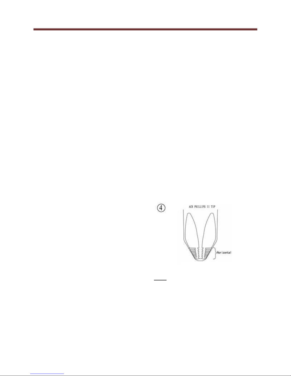
Phillips-head screws are often damaged
by incorrectly fitting screwdrivers.
Quality Phillips screwdrivers are
manufactured with their crosshead tip
machined to Phillips Screw Company
specifications. Poor quality or damaged
Phillips screwdrivers can back out and
round over the screw head. Weak or
soft screw materials can make removal
more difficult. The best type of
screwdriver to use on Phillips screw is
the CR Phillips II screwdriver, patented
by the horizontal anti-cam out ribs found
on the driving faces or flutes of the
screwdriver’s tip (figure 4). CR Phillips
II screwdrivers were designed as part of
a manufacturing drive system to be
used with CR Phillips II screws, but
they work well. Tool suppliers offer CR
Phillips II screwdrivers in different Tip
size and interchangeable bits to fit
screwdriver bit holders.
Note
Another way to prevent the
screwdriver from rounding out the
head of the screw is to apply valve
grinding compound onto the tip. After
loosening or tightening the screw,
clean the screw recess to prevent
engine oil contamination.
Table of contents
Other Hisun Utility Vehicle manuals

Hisun
Hisun HS700UTV-4 Manual

Hisun
Hisun HS500UTV User manual

Hisun
Hisun Strike 250 User manual

Hisun
Hisun HS164-4 User manual

Hisun
Hisun HS500UTV User manual

Hisun
Hisun HS1P65MM User manual

Hisun
Hisun HS294-2 Owner's manual

Hisun
Hisun STRIKE 800 User manual

Hisun
Hisun HS250UTV Owner's manual

Hisun
Hisun SECTOR 1000 User manual


