manuals.online logo
Brands
  1. Home
  2. •
  3. Brands
  4. •
  5. Hitachi
  6. •
  7. Air Conditioner
  8. •
  9. Hitachi RAS-08HT User manual

Hitachi RAS-08HT User manual

1
Installation Instructions
Split Inverter Type
Room Air Conditioner
Cooling Type Series
Indoor Units Outdoor Units
RAS-08HT
RAS-10HT
RAS-15HT
RAS-19HT
RAS-24HT
RAS-30HT
RAC-08HTP
RAC-10HTP
RAC-15HTP
RAC-19HTP
RAC-24HTP
RAC-30HTP
Installation Notices
⚫Dealers must explain in details the operations to their customers according to this manual.
⚫Wireless remote controller and parts are packed in the packing box supplied with the indoor unit.
⚫Before installing, check if the power supply and circuitry are normal and make sure the voltage is within ±10% of the
voltage rating.
⚫The distance of in the installation diagram is to ensure space for the air conditioner’s performance. For
convenience of service and maintenance in the future, install the air conditioner in the place with sufficient space in
the vicinity.
⚫Care should be taken in cutting, extension and bending of the refrigerant piping and not to break the pipes.
As this air conditioner uses new recyclable refrigerant, ”R410A” be sure to follow three principles - keeping
the refrigeration system dry, clean, and air tight, when installing the refrigerant piping.
Caution
(Failure to observe the following items may cause serious consequences or
damage to the objects)
damages to the objects)
⚫Installation of air conditioner and electrical wiring must be handled by authorized installer only, do not attempt to handle
them by yourselves (Handling charges are additional.)
⚫Before installing, read the installation instructions thoroughly and correctly.
⚫Use only those specified accessories when installing, otherwise, it may cause the unit body to fall, water leakage, current
leakage and fire, etc.
⚫When discharging, refrigerant is required during installation, be sure to use an air vent and air breather, as refrigerant will
produce toxic gas once it mixes with hot air.
⚫When performing wiring work, be sure to follow the electrical codes and installation instructions, and also be sure to use the
power loops exclusively for the air conditioner.
⚫When installing or moving the units, the refrigeration system (piping) must not mix with refrigerant R22 or air, except
refrigerant R410A. If air is mixed in, the system capacity will reduce, causing abnormal high pressure in the refrigeration
system that may lead to copper tube breaking and failure to occur.
Warning
(Failure to observe the following items may cause injury or death)
【Contents】
Installation Notices.......1
Indoor Units Installation
Instructions..................4
Outdoor Units Installation
Instructions..................9
Environmental
Protection
Before installing the
air conditioner, read
this instruction
manual thoroughly
and keep it well for
reference in the
future.
2
To prevent current leakage:
⚫To avoid carelessness from power companies or other accidents that cause over current to get into the unit via the earth
wire resulting in damage to the unit, be sure to install a circuit breaker. Refer to the dealers (the qualified technicians) for
details.
⚫To prevent electric shock in case of current leakage, the outdoor unit must be connected with an earth wire with wire
specification of 2.5mm2to 6mm2.
(When hooking up the earth wire, the installer must first handle the end tip of the wire. After crimping the wire with a ring
terminal, make sure to screw down the earth wire tightly to complete grounding at the place marked with a grounding
sign near the access panel combination or the valve base combination.)
⚫When installing near places with high humidity such as bathing facilities, damp, humid places, basements, and places
with frequent water accumulation, be sure to install a circuit breakers preventing leakage. Refer to the dealers (the
qualified technicians) for details.
1. To ensure your safety, this product must not be used in the highly humid areas such as laundry room and bathroom,
etc.
2. The earth wire must not be connected to the following positions:
⚫Water pipes: If there is a plastic pipe in the pipelines, do not connect the earth wire to the pipeline.
⚫Gas pipes: There is risk of explosion after ignited.
⚫Ungrounded neutral lines in the electrical circuit panel, earth wires of the telephone line and lightning rods, etc, which
may have large amount of current flowing through tending to cause danger when lightning strikes or by other factors.
⚫The units must be installed at the places where sufficient
supports are available, vibration-free, firm and stable places.
⚫There are no heat sources, fumes in the vicinity and no barriers
around the air outlet.
⚫There should have some clearance in the distance as indicated
by in the diagram ( page 4) on the top, left and right
sides of the unit.
⚫Places where it is convenient for the unit to drain water and to
connect piping of the outdoor units
⚫To avoid noise effect, keep the unit and the remote controller
1m or above away from TV and radio, etc.
⚫To avoid errors in the remote controller; keep the controller
away from high frequency machines and wireless machines
with high power output.
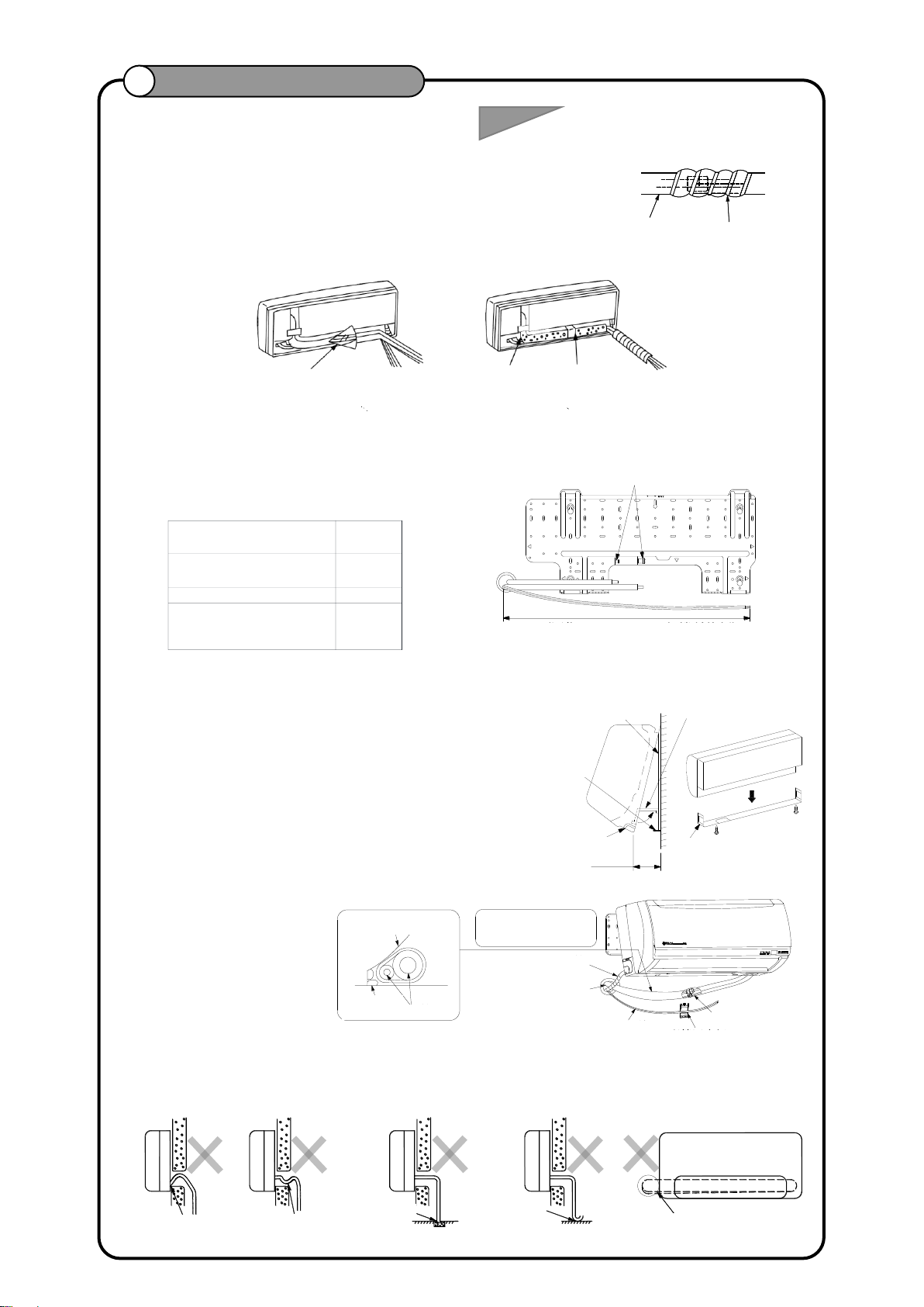
⚫Make sure the pullout direction of the pipes:
There are four pullout
directions for the pipes -
straight backward,
downward, leftward and
rightward.
⚫Do not install the unit at the places easy to expose rain or
direct sunlight, but at the places where there are frequent
airflows.
⚫The airflow must not face directly to animals and plants.
⚫On the top, left, right, front and rear sides of the unit, there
must leave clearance in the distance as indicated in the
diagram ( page 4). At least two sides should be open,
where one side is for the outflow.
⚫The outflow air and noises must not annoy neighbors.
⚫The units must not be installed at the places where flammable
gas, vapor, dust and fumes are available.
⚫The drain hose must be kept unclogged.
⚫The outdoor units must be installed at the places capable of
sustaining heavy weight, otherwise, the noise and vibration will
be amplified, tending to cause the unit to fall or personal injury.
Installation dimensions of outdoor units(mm)
Models
A
B
C
D
E
RAC-08HTP
554
335
148
45
279
RAC-10HTP
RAC-15HTP
RAC-19HTP
509
335
214
100
237
RAC-24HTP
530
335
287
175
245
RAC-30HTP
NOTICE
Earth wire and earth leakage circuit breaker.
Pulling
leftward
Pulling
straight
Pulling
downward
Pulling
rightward
Outdoor
Units
Pulling rightward
Pulling downward
【Content
s】
Installation
Notices .......................1
Indoor
Units
Installation
Instructions..................5
Indoor
units
Selection of installation locations (Confirm the location before installation)
A C
B
E
D
drain hose
3
Electric Specification
•Screw driver
•Tape measure
•Knife
•aw
•Ø65, Ø5mm Drill bit
•Allen wrench (diameter, 5mm)
•Adjustable wrench and torque wrench
•R134a (R410A) Gas leakage tester or soapsuds
•Tubing cutter
•Flaring tools (for R410A only)
•Adhesive-free tape
•Pliers
•Vacuum pump (for R410A only)
•Electronic scale
Models
Gas
pipe
Liquid
pipe
Connection Wires
Specification
Power Supply
Wire Specification
Fuse Capacity
RAS-08HT / RAC-08HTP
Ø 9.53
Ø 6.35
1.25mm² Stranded
Wire + Blade
terminal
Ø 2.0mm
Single-core Hard
Wire or 3.5mm²
Stranded Wire
10A
RAS-10HT / RAC-10HTP
RAS-15HT / RAC-15HTP
Ø 12.7
15A
RAS-19HT / RAC-19HTP
RAS-24HT / RAC-24HTP
Ø 15.88
20A
RAS-30HT / RAC-30HTP
•Be sure to use new refrigerant pipe for piping (replace the R22 used pipe with new pipe, recycling the old R22 pipe
after cleaning is prohibited).
•Pipe size to be adopted for installation shall be as per specified specification, pipes with different size with the
indoor unit is prohibited for piping.
•It is required for unit installation that two open installation faces are reserved with one of them for unit air outlet.
•Installation distance between the indoor unit and other appliances, such as the fluorescent lamp, television, radio
and so on, shall be above 1 meter to prevent the signal interference.
Wiring Diagram
Required Tools for Installation
Do not use the connection wires together with the
same cable for the power supply wire to prevent
signal interference that may cause errors.
NOTICE
•
SCAN ME
Scan this QR code
with your mobile
device to see
further instructions
on how to
maximize the
functions of your
air conditioner and
for other related
information.
⚫The outdoor unit base is provided
with a drain hole for condensed
water.
⚫To drain condensed water by using
the drain hole, lift the unit about
70mm or more above the ground,
and then fit the drain elbow as
shown in the above diagram.
Screw it tight in clockwise direction
at an angle about 40∘.
⚫Install the outdoor unit on Series.
Check that the condensed water
can drain normally.
⚫The drainpipe (VP16) should be
supplied locally.
Handling condensate from the outdoor unit
NOTICE
The condensed water drain tray for the indoor unit can be fitted
from the left or right side. Hence, the installation plate must be
kept in a Series when fixing it, or the side fitted with the drain line
must be slightly tilted downward. Otherwise, the condensed
water may spill out.
Maximum allowable height of tilt for the indoor and outdoor unit
.
服務蓋
螺絲遮蓋
輕摳此處可拆下
固定螺絲
+
Indoor Units Installation Instructions
Hanging
first
Above 70mm
Press in
Removal of access panel of the indoor unit
Step 1:
Remove the fixing screws of the
screw cover beneath the unit
and the access panel.
Step 2:
Support the access panel under
the base with two hands and
apply pressure inward on the
“ ” of two sides, until the
hook inside the access panel is
released from the base.
(A clear sound of “da” can be
heard when the hook is
released.)
Step 3:
After the hooks on both sides are
released, the access panel
beneath the unit can be removed
downward with both hands. After
the access panel is removed,
there has more space for wiring
and piping work.
Fixing screw
Access panel
Not higher than a
Not higher than a
Models
7
a (mm)
10
RAS-08HT
RAS-15HT
RAS-10HT
RAS-24HT
RAS-19HT
RAS-30HT
dig here slightly to remove
Screw cover
4
Note: To let the indoor unit attach closely to the wall, the base and
the installation plate can be tightened and secured by using
the item ②screw after piping work is completed, and then
assembly the access panel.
⚫Secure the installation plate by using the intermediate post
between walls.
⚫Installation procedure for fitting the installation plate on
the wall.
1. Drilling on the wall.
2. Aligning with the
hole on the
installation plate.
⚫When fitting the installation plate, the figures printed on the
bottom of the packaging carton of the unit can be used to
position.
3. Secure the installation plate on the wall by
using Item special screws.
Level
Installation plate
Special screw
Inscription
Thread Plummet Piping hole
Assembly of access panel of the indoor unit
Additional fixing to the installation
plate and the base
Fitting the installation plate
1
Secure it with 4 or
more special
screws
Series
08~15
Wall
Installation plate
Knock in or
screw in
Wall
Φ5mm
Special
screw
Contour of the shape of the indoor unit
a b
ab
Step 1:
Align the round fixing axis with the rectangular hole below the
base and insert it all the way upward.
Step 2:
Align the hooks on both sides with the guiding slots on the
base and push slightly upward from the bottom of the access
panel until the base engages in the access panel and the
surfaces are flush. (A clear “da” sound can be heard when the
hook is engaged.)
Step 3:
Tighten the fixing screw that fixes the access panel to the
bottom of the unit.
Step 4:
Press the screw cover into the access panel.
服務蓋
螺絲遮蓋
Screw cover
Access panel
螺絲
底座
安裝架
Base
Screw
①
Installation plate
Above 70mm
Ceiling
Special screw
(The diagram is an instance of RAS-20NF)
RAS-08HT)
Series
19、24
Models a
RAS-08HT
RAS-10HT 93
82
RAS-15HT
b
88
88
88 88
RAS-19HT
RAS-24HT
unit : mm
RAS-30HT
②
5
⚫When drilling a hole of
Ø65mm in diameter,
keep the outdoor side
slightly downward and
drill it with a small slope.
⚫Cut the tube guard
based on the thickness
of the wall to be installed.
⚫The clearance of pipe
plugs must be sealed
completely to prevent
rain from penetrating
indoor.
Drilling the wall and fitting the tube guard
2
When connecting the
wires, do not let the wires
come in touch with the
metal grids inside the wall;
In addition, if the wires run
through a hollow wall,
there is risk of being bitten
by rats and causes
danger. Be sure to use the
tube guard.
NOTICE
Indoor side
Outdoor
side
Tube guard
Putty
Pipe plug
Wall
⚫To pull down the pipes directly:
1. Remove the access panel, then pull
out the connection wires and joint
them.
2. Pull out the pipes, connection wires
and the drain hose.
⚫To pull the pipes horizontally, replace and
fit the drain hose and drain cap as shown
below. In addition, the drain hose must be
inserted all the way in.
⚫Turn and remove the drain cap by using a
plier (this method is easier to remove the
cap) as shown in the right diagram.
⚫To pull the pipes leftward or
rightward and downward, use tools
such as a saw to cut and remove
the plugs or access panel as
shown below and then trim the
burr.
⚫The drain cap and drain hose must be inserted
completely, or the condensed water may spill over.
Preparation for installing the indoor unit
3
NOTICE
Connection wire,
pipes and drain
hose must be
secured using a
tape.
Drain cap
Pull it out from access panel
Drain hose
Plug
Access
panel
Plug
Drain cap
Drain hose
Insert it to
here
Insert it to
here
Access panel
Plug
Plug
6
When wrapping too
forcibly the insulation
material for fitting by a
tape, the insulation
effect will reduce and
causes condensation.
A.To install the indoor unit after jointing the
refrigerant lines:
⚫The junction of pipes must be wrapped with
insulation materials for fittings.
⚫Connect the power lines.
⚫After arranging the connection wires and pipes,
place them in the space at the bottom of indoor
unit and secure them with tie wraps.
⚫The insulation pipes must be wound by tape at
every 120mm.
B.To install the indoor unit before jointing
the refrigerant pipes:
⚫Refrigerant lines and connection wires must be
tied together.
⚫For the length of the refrigerant lines to be
reserved, refer to the right diagram.
⚫For the length of connection wires to be
reserved, refer to the table below.
(The diagram is an instance of RAS-08HT)
C.Installation
⚫Hang the indoor unit onto the installation plate.
⚫Keep the bottom of the inside unit moving forward about 15
cm by using the tie wrap on the back of indoor unit to support
against the wall.
⚫Remove the access panel at the bottom of the indoor unit.
⚫Insert the drain hose in the hole on the wall.
⚫After pipes are jointed, the junctions should be wrapped with
insulation materials for fittings.
⚫Jointing connection wires.
⚫After arranging the connection wires and pipes, place them in
the space at the bottom of indoor unit and secure them with
tie wraps.
⚫The pawl at the bottom of indoor unit must securely engage
the hook of the installation plate.
⚫Finally replace the access panel on the unit.
D. Draining precautions
積水 積水 前端
積水
排水溝
⚫When pulling
horizontally, the front
end of drain hose must
not be higher.
⚫The front end of
the drain hose
must not be
dipped in water.
⚫The drain hose
must not be
bent in waves.
⚫The drain hose
must not point
up.
⚫The front end
of the drain
hose must not
point up.
NOTICE
Installation of the indoor unit
4
Insulation material for fittings
Insulation pipe Tie wrap
固定爪
安裝板
固定勾
約15cm
服務蓋
配管固定束帶
Wrapping too
forcibly with a tape
Pipe
The front end of the refrigerant pipe must be
positioned at the location inscribed with marks.
Installation
plate
Pawl
Tie wrap
Access panel
About 15cm
Hook
Water sump
Water sump
Ditch
Water sump
Front end
( L cm )
(圖像以RAS/RAC-20級機種為例)
Models
70
L
RAS-08HT
RAS-10HT
110
RAS-24HT
RAS-15HT 95
RAS-19HT
RAS-30HT
管接頭隔熱材
連接電線 配管
配管接續時,需向前
拉出,配管才容易。
保護管
排水管
連接電線 配管固定板
接續部
Pipe
Connection
wire
Insulation material
for fittings
When jointing a pipe, it
must be pulled forward
to make piping easier.
Tube guard
Drain hose
Connection wire
Tip wrap
Junction
7
Run the connection wire from the back of unit to
the front.
Lift up the panel. (See page 4 in the user
manual for instructions)
After removing the screws fixing the electric
access panel, lift up the electric access panel
and joint the connection wires.
Use Φ1.25mm stranded wire + flat insulation
terminal to connect the connection wires.
The flat insulation terminal after inserted in the
terminal board, it must be secured by tightening
the screw. Make sure that each wire is secured
and will not be pulled out; otherwise, the
terminal board may be burned out resulting in
the unit incapable of working, as shown in the
right diagram.
⚫Be sure to use the power loop exclusively for
the air conditioner only.
⚫For installation method of the connection
wires, refer to technical reference related to
electric facilities.
⚫Before energizing the connection wires
between the indoor and outdoor units, the
earth wire of the outdoor unit must first be
earthed. Conversely, the connection wire
between the indoor and outdoor units should
first be removed before the outdoor earth
wire is removed.
⚫Do not use the same cable for the connection
wires and the power supply wire to prevent
signal interference that can cause errors.
Remove the cap nut.
(Helium in the indoor unit will be
discharged)
After tightening with wrench, slightly rotating
backward and tighten with torque wrench. For small
diameter pipes, to avoid screwing too tightly, use a
torque wrench.
When jointing pipes, align the pipes
with hands and screw them to the
end.
(Before jointing, apply some
refrigerating oil at the flare opening.)
[Tighten to the end with hands]
[Tightening torque]
外徑(Φ)
扭力(kgf-cm)
細徑側
6.35(1/4")
140~190
粗徑側
9.53(3/8")
350~450
粗徑側
12.7(1/2")
450~550
粗徑側
15.88(5/8")
500~600
Jointing of connection wires and securing method
6
Jointing pipes
5
hsiu
Piping of indoor unit
Flare nut
Don’t screw all the
way in a sudden,
but screw slowly
until they are tight.
⚫Care should
be taken when
bending the
pipes.
Liquid diameter
pipes
Gas diameter
pipes
Gas diameter
pipes
Gas diameter
pipes
Outer
diameter(Φ)
Torque (kgf-cm)
NOTICE
6mm 30mm
Inner covering
stranded wire
Stripped length of the connection wire.
Outer covering
(Insert securely)
The screw must be
tightened to secure
the connection
wire.
fixed the flat insulation
terminal
CD terminal
board
Connection
wire
Secure with crimping tools
Stranded wire
Flat insulation termainal
(stripped length)
6mm
10
18mm
To remove the
connection
wires,
unscrew the
screws.
Flat insulation
terminal
Covering
Connection
wire
NOTICE
8
12mm
15mm
Use stranded wire of
(N0.1) (N0.2)
D
CN
L
D
C
N
LD
C
N
L
D
CN
L
D
CC D C DL N D
C
N
LD
CD
CD
C
N
LD
CD
CD
C
L N C D C D
D
C
N
L
D
CN
L
D
CD
CD
C
5.5mm as power
supply wire
●
●
● ● ● ●
● ● ● ● ●
●
⚫For handling of the junction of the connection wires, refer to the instructions of indoor units. (Refer to the
diagrams below for the scheme after jointed)
⚫For specifications of the power supply wire and the connection wires, refer to the specification specified in the
table of “Electric specification” on Page 3.
⚫Description of the jointing method:
Remove the upper cover (for RAC-08HTP~10HTP) or electric access panel (for RAC-15~30HTP) or service
cap.
Joint each wire as specified in the diagram.
Replace the upper cover or the electric access panel or service cap and valve cap.
Outdoor unit installation instructions
1
For the fitting method of the connection wires, refer to the
technical reference related to the electric facilities,
NOTICE
●Wire attachment must be firmly secure, poor tightening or misconnection is contributable to burn-down of the circuit board.
●Use stranded wire of 2.5~6.0mm2as the earth wire and the wire must be crimped with a ring terminal before attached to
the earth wire screw. The screw must be tightened securely without loosening.
C D NL
電源線
接地線
連接電線
鎖緊固定
螺絲確實
˙ RAC-40~50級
CNL D
˙ RAC-22~36級˙ RAC-63級
鎖緊固定
螺絲確實
電源線
連接電線
接地線
鎖緊固定
螺絲確實
接地線
電源線
連接電線
C
NL D
The screws must
be tightened
securely
Power supply
wire
Connection wire
Earth wire
Earth wire
Connection
wire
Power supply
wire
The screws must
be tightened
securely
The screws must
be tightened
securely
Earth wire
Power supply
wire
Connection
wire
Connection
wire
b
使用單芯硬線時,不需使用圓形端子
LN端子台 電源線
螺絲須確實鎖緊
The screw must be
tightened securely
LN terminal board
Power supply wire
When using single-core hard wires.
no ring terminals are required.
Secure with crimping tools
Stranded wire
Flat insulation termainal
(stripped length)
6mm
10
(Insert securely)
The screw must be
tightened to secure
the connection
wire.
fixed the flat insulation
terminal
CD terminal
board
Connection
wire
RAC-08~10HTP
RAC-15~19HTP
RAC-24~30HTP
⚫Instructions of power line (LN terminal board) tip handling and slicing
⚫
⚫Instructions of power line(LN terminal board)tip handling and slicing.
•
⚫Instructions of power line(LN terminal board)tip handling and slicing.
⚫Instructions of splicing the connection wires (CD terminal board)
Connection
wire
Jointing the connection wires and
the power supply wires
9
●The pressure of refrigerant R410A is higher than
that of R22, and thus the thickness of copper
pipes must comply with that shown in the right
table. The copper pipe of 0.7 mm thickness
available on the market must not be used.
⚫Cutting and flaring operation of copper tubes 。
Use pipe cutter to cut the copper pipe
perpendicularly.
Thickness of copper pipes for general refrigerant pipes.
Nominal outer
diameter (inch)
Standard outer
diameter (mm)
Thickness of copper
tube (mm)
Ø1/4
Ø6.35
0.8
Ø3/8
Ø9.52
0.8
Ø1/2
Ø12.7
0.8
Ø5/8
Ø15.88
1.0
Before flaming the pipe with a flaming tool, do not forget
to fit a flare nut.
A (mm)
Outer diameter
(Ø)
Tool for R410A
Tool for R22
6.35(1/4")
0~0.5
1.0
9.53(3/8")
0~0.5
1.0
12.7(1/2")
0~0.5
1.0
15.88(5/8")
0~0.5
1.0
When deburring the copper pipe, point
down to the pipe to avoid copper chips
coming in the pipe.
Perform the pipe flaring.
Check the pipe flares. Poor flaring
will cause leakage when they are
jointed.
⚫Example of poor flaring:
Incomplete deburring Copper chips scratch the inside Under flaring Over flaring Cracking
Notice: Before joining the pipes, apply some refrigerating oil at the flare opening
to ensure no leakage from the joint.
Remove the
flare nut.
Align and
tighten the
pipe end with
hand.
Aftertighteningwitha wrench,slightlyscrew
backward and then tightenit usingthetorque
wrench.
[Tightening torque]
Outerdiameter
(Ø)
Torque (kgf-cm)
Liquid diameter
6.35(1/4")
140~190
Gas diameter
9.53(3/8")
350~450
Gas diameter
12.7(1/2")
450~550
Gas diameter
15.88(5/8")
500~600
Do not tighten all
the way in a
sudden, but screw
slowly and tight it
[ Screw all the way
down with hand] ]
Scratches
Sand enters the
pipe
Cap and plastic
Tying with a
rubber band
Wall
Copper chips and copper
powder come in the pipe
Burr
Deburring tool
Pipe
Foreign
matters and
water enters
Ground
Foreign matters and
water enters
Cap and
plastic
Without
touching
the ground
Rubber band
Ground
Cap and plastic bag
Tying with a rubber
band
Rain enters
the pipe
Outdoor
Indoor
Sealed
Sealed
Outdoor
Indoor
Outdoor
Indoor
Precautions for refrigerant piping
3
【Size of overhang
of copper pipe】
Preparing the pipes
2
Jointing the pipes
4
(Strictly observe the size of overhang to
avoid leakage.)
Tighten the pipe
cutter to cut the
copper pipe
Flaring tool
Screw gripper
Flare nut
Copper pipe
Rotate to right
to feed the
knife.
Pipe cutter
Copper pipe
Handle
Tighten the pipe
cutter to cut the
copper pipe
Deburring tool
Ensure that the
inside of copper
tube has no
scratches.
Copper pipe
Press
die
10
⚫As the outdoor unit contains
refrigerant without leakage, to
maximize the unit’s performance, be sure to
use the following vacuum pump method to
vacuum the system after piping work of the
indoor and outdoor units is finished.
⚫When vacuuming, it is not necessary to run
the units.
⚫Before trial run, do not turn on the power to
the air conditioner.
⚫Using the vacuum pump method
Connect the vacuum pump with a
composite pressure gauge as shown in the
right diagram.
It closes when the knob at Hi position, it
fully opens when the knob at Lo position.
Startup the vacuum pump.
Now loosen the flare nut of the service
valve on the small tube side and make sure
air is sucked in, if yes, tighten the flare nut
immediately.
Keep the pump working for 10 to 15
minutes. When the composite pressure
gauge indicates -0.1MPa (-76cmHg), fully
close the knob Lo.
Stop the vacuum pump.
Remove the valve cap and fully open the
spindles of the service valves of the small
and large tube sides by turning the Allen
wrench in the counterclockwise direction.
Then, remove the charging tube and tighten
the valve cap and service valve nut by the
tool such as a wrench.
NOTICE
⚫When fitting the check valve, ensure that
the arrow on the check valve points to the
vacuum pump.
⚫When power outage happens during
vacuuming, open the discharge vent of the
composite pressure gauge to let it reach
normal pressure. Then, tighten the vent to
re-do vacuuming.
⚫Service valve operating precautions
Screw the spindle until it clutches, excess
force will cause failure.
Tightening torques for the valve head nut and
the valve core nut are shown in the right table.
⚫Check gas leakage
Use soap suds or “gas leakage tester R134A
(R410A)” to check if refrigerant leaks from the
joint of the flare nut, if yes, tighten the nut to
avoid leakage. Wipe off the soap suds after
check.
六角
扳手
閥頭帽
服務閥 閥心帽
閥頭帽
Vacuum Operation
5
Be sure to use the vacuum pump
exclusively for R410A or install an oil
check valve (solenoid valve) to prevent
unidentified refrigerating oil from entering in
the unit, resulting in damage to parts and
failure to the unit. Strictly observe this!
●Using the refrigerant left in the unit is
prohibited be sure to use the composite
pressure gauge and refigerant charging
hose exclusively for R410A.
NOTICE
Charging
hose
Vacuum pump
Pump check
valve
Service valve
(Liquid pipe)
Service valve
(Gas pipe)
Ball valve
switch
Knob Switch Hi
Ball valve switch
Composite
pressure gauge
Charging hose
-0.1Mpa
Flare nut
Flare nut
Allen
wrench
Service
valve
Service
valve nut
Valve cap
Valve cap
Valve cap 200~250kgf-cm
Valve cap 125~160kgf-cm
[Tightening torque]
Discharge vent
Knob Switch Lo
11
⚫After installation, check the piping, wiring, length
of connection wires and power supply wire
inserted in the terminal board and their polarities
(or signs) are correct.
⚫This product will absorb the noises produced by
static electric charge, be sure to connect the
earth wire.
⚫To avoid current leakage, be sure to install a
“high sensitivity, high speed earth leakage circuit
(for inverter).”
⚫The remote controller can be attached to the
wall, column or table by using the remote
controller holder.
⚫If the remote controller is to be operated on the
holder, make sure that the unit can receive the
signals sent from the position of remote
controller before determining the position to be
installed. The unit will react with a “beep” sound
when receiving a signal. The signals can be
attenuated due to the fluorescent tube, so when
determining the position of installation, even if it
is daytime, the light must be turned on.
⚫Attach the remote controller with wood screws
at the suitable position. (Do not attach it to the
places where it can expose to direct sunlight
and places where strong heat can generate)
⚫Insert the remote controller in its holder. (As
indicated by the arrow in the diagram)
Types
Models
Length of
pipes
without
necessity
of refilling
refrigerant
Recharge
refrigerant
when the
pipeline is
extended
(g/m)
Maximum
piping
length
(m)
Single split
RAC-08HTP
RAC-10HTP
No longer
than 10m
10
20
RAC-15HTP
10
30
RAC-19HTP
20
RAC-24HTP
RAC-30HTP
15
⚫As R410A is mixed refrigerant, if charged in gas
phase the components of refrigerant will alter,
which will affect normal working of the system. So,
be sure to charge refrigerant in liquid phase.
⚫Verify indications on the refrigerant cylinder. If the
refrigerant cylinder does not contain a siphon, the
cylinder must be positioned upside down; if it
contains a siphon, the cylinder must be positioned
upright.
⚫To ensure a correct refrigerant recharging quantity,
use an electronic scale.
⚫When refrigerant recycle or outdoor-unit-only
operation is carried out, please turn off the breaker
firstly, then open the switch and wait 1 minute at
least, and then press the service switch for 1
second at least on the main PCB of the outdoor
unit to start the unit operation.
⚫Press the service switch again for 1 second at least
to stop unit operation.
⚫After unit stoppage, please turn off the breaker, and
then turn on it again to return to the normal state
mode.
⚫To protect the compressor, please do not operate
the unit for more than 5 minutes when the service
valve is closed.
⚫Maintenance operation is for professional
repairmen use only, users are prohibited to
operate it.
⚫Please do not operate the unit with the service
valve closed for more than 5 minutes to prevent
the unit malfunction.
Test run
1
Test run check
1
Installation of a remote controller holder
3
Refrigerant recharging
4
Test run and other precautions
6
Test run
2
Maintenance operation
5
NOTICE
Remove
Wood screw
Insert
holder
Remote conntroller
Φ6.5mm
Wall
30mm
Drilling on the wall
Plug
Remote controller
66MP1385-A1
12

This manual suits for next models

11

Other Hitachi Air Conditioner manuals

Hitachi RAS-80YH5A User manual

Hitachi

Hitachi RAS-80YH5A User manual

Hitachi MULTIZONE RAI-25RPE User manual

Hitachi

Hitachi MULTIZONE RAI-25RPE User manual

Hitachi RAD-18NH7A User manual

Hitachi

Hitachi RAD-18NH7A User manual

Hitachi RAS-50FH7 User manual

Hitachi

Hitachi RAS-50FH7 User manual

Hitachi RAS-19SH4 User manual

Hitachi

Hitachi RAS-19SH4 User manual

Hitachi PSC-AS2048WXB User manual

Hitachi

Hitachi PSC-AS2048WXB User manual

Hitachi airHome 600 User manual

Hitachi

Hitachi airHome 600 User manual

Hitachi RPK-0.8FSNQS User manual

Hitachi

Hitachi RPK-0.8FSNQS User manual

Hitachi RAS-X10CZ User manual

Hitachi

Hitachi RAS-X10CZ User manual

Hitachi RAS-E10HB User manual

Hitachi

Hitachi RAS-E10HB User manual

Hitachi RAM-52QH5 User manual

Hitachi

Hitachi RAM-52QH5 User manual

Hitachi airHome 400 User manual

Hitachi

Hitachi airHome 400 User manual

Hitachi RAK-DJ18PHAE User manual

Hitachi

Hitachi RAK-DJ18PHAE User manual

Hitachi RAK-25PEB User manual

Hitachi

Hitachi RAK-25PEB User manual

Hitachi RAS-18KH(T1) User manual

Hitachi

Hitachi RAS-18KH(T1) User manual

Hitachi RCI-1.0FSN3 User manual

Hitachi

Hitachi RCI-1.0FSN3 User manual

Hitachi RAS-E10CBT User manual

Hitachi

Hitachi RAS-E10CBT User manual

Hitachi RAS-X18CD User manual

Hitachi

Hitachi RAS-X18CD User manual

Hitachi RAK-35RPC User manual

Hitachi

Hitachi RAK-35RPC User manual

Hitachi RAC-AJ10PCASM User manual

Hitachi

Hitachi RAC-AJ10PCASM User manual

Hitachi RCI-1.0FSN1E User manual

Hitachi

Hitachi RCI-1.0FSN1E User manual

Hitachi RAI-25NH4 User manual

Hitachi

Hitachi RAI-25NH4 User manual

Hitachi airCore 700 Instruction Manual

Hitachi

Hitachi airCore 700 Instruction Manual

Hitachi RPIL-1.0UNE1NH User manual

Hitachi

Hitachi RPIL-1.0UNE1NH User manual

Popular Air Conditioner manuals by other brands

Mitsubishi Electric PLA-RP BA3 Technical data book

Mitsubishi Electric

Mitsubishi Electric PLA-RP BA3 Technical data book

Mitsubishi Electric PEAD-A24AA4 installation manual

Mitsubishi Electric

Mitsubishi Electric PEAD-A24AA4 installation manual

General AUHA12LAL Service manual

General

General AUHA12LAL Service manual

Dantherm Master BCF 330AB User and Maintenance Book

Dantherm

Dantherm Master BCF 330AB User and Maintenance Book

Samsung RJ040F2HXEB installation manual

Samsung

Samsung RJ040F2HXEB installation manual

Linea DOMO DO157A Instruction booklet

Linea

Linea DOMO DO157A Instruction booklet

Haier HW-18CG03 Operation manual

Haier

Haier HW-18CG03 Operation manual

Pridiom CS494U-BPY user manual

Pridiom

Pridiom CS494U-BPY user manual

Daikin EBLQ05+07CAV3 Installer's reference guide

Daikin

Daikin EBLQ05+07CAV3 Installer's reference guide

Daikin Altherma 3 R W EHB Series installation manual

Daikin

Daikin Altherma 3 R W EHB Series installation manual

Midea MOU-18HN1-Q Service manual

Midea

Midea MOU-18HN1-Q Service manual

Soleus Air 000/12 - BTU Multi-Room Heat/Cool Room Air... operating instructions

Soleus Air

Soleus Air 000/12 - BTU Multi-Room Heat/Cool Room Air... operating instructions

TemperZone OSA 83RKSH Installation & maintenance

TemperZone

TemperZone OSA 83RKSH Installation & maintenance

Daitsu ADP 9AM instruction manual

Daitsu

Daitsu ADP 9AM instruction manual

Fral SUPER COOL FSC09C user manual

Fral

Fral SUPER COOL FSC09C user manual

Samsung MH080FXEA4B installation manual

Samsung

Samsung MH080FXEA4B installation manual

Daikin FXLQ12MVJU installation manual

Daikin

Daikin FXLQ12MVJU installation manual

Fujitsu ASUH12LPAS Design & technical manual

Fujitsu

Fujitsu ASUH12LPAS Design & technical manual

manuals.online logo
manuals.online logoBrands
  • About & Mission
  • Contact us
  • Privacy Policy
  • Terms and Conditions

Copyright 2025 Manuals.Online. All Rights Reserved.