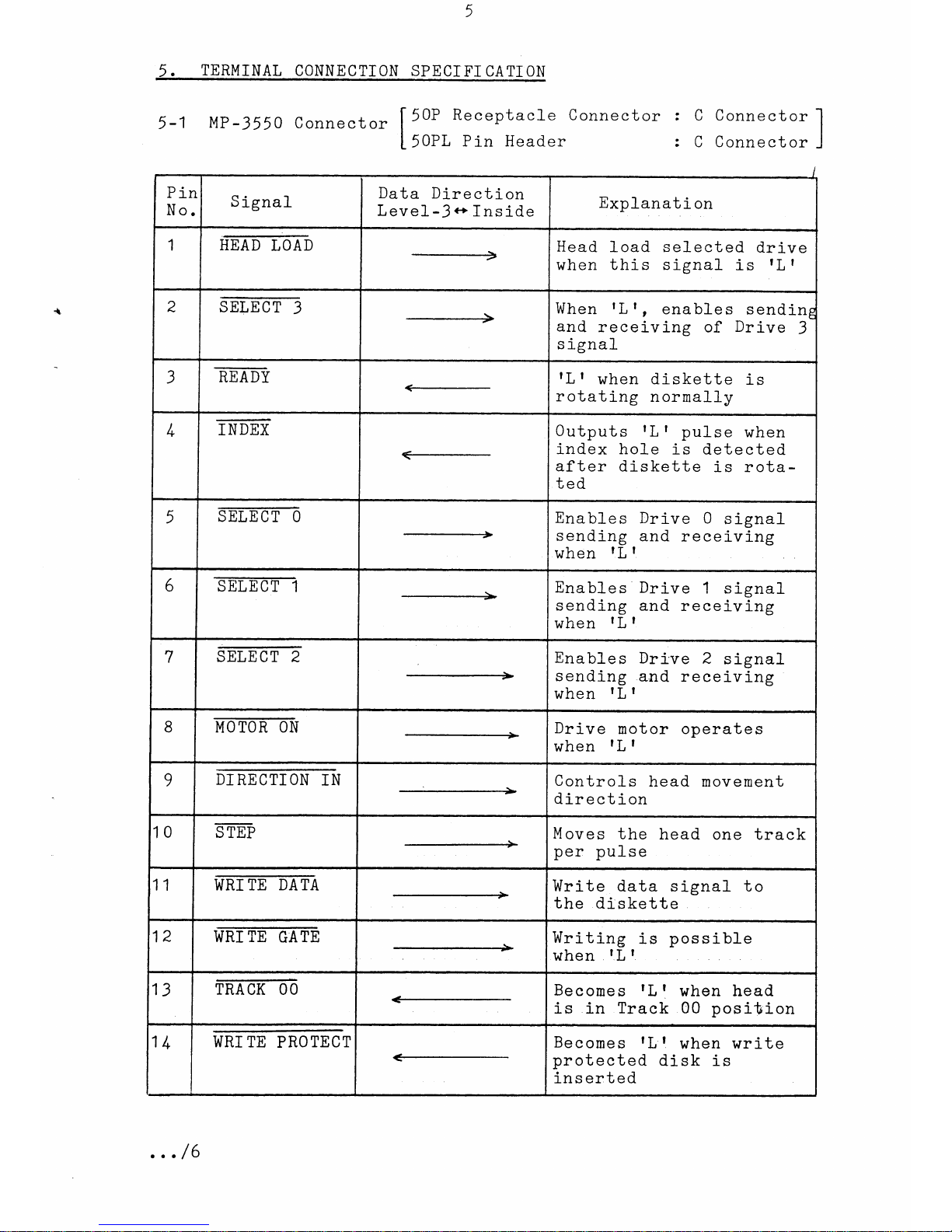
5-1 Mp-
3550
connector Ilor Receptac]-e
connector : c connector
II
L
50PL Pin Header : C Connector J
q
/
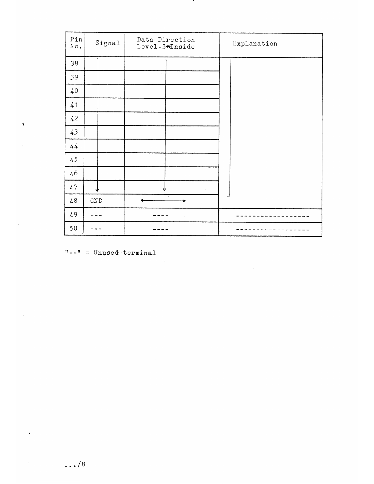
5. TERMINAL
CONNECTTONSPECTFI
CATI..ON
Pin
No. S
ignal Data Direction
Level-3c' Inside Expl-anati on
1HEAD
LOAD Head l-oad selected drive
when this signal is tL I
2SE_IEET-3 ___-__--_-> When rL|
, enables sendin5
and receiving of Drive 3
signal
3ET.DY rL I when diskette i-s
rotating normally
/, INDEX <- Outputs rLf pulse when
index hole is detected
after diskette is rota-
ted
5m0 Enables Drive 0 signal
sending and receiving
when lL I
6SIET1 ------=-+ Enables Drive 1 signal
sending and receivi-ns
when lL I
7mffi Enables Dri've 2 signal
sending and receiving
when lL I
8MOTOR
ON Drive motor operates
when lL I
9DI
RECTI
ONIN Control-s head movement
direction
10 S
TEP t
+Moves the head one track
per pulse
11 i[mTETlm Write data signal to
the diskette
12 WRI
TE GATE Writing is possibl-e
when tLt
13 TRACK
OO Becomes tL
t when head
is in Track 00 position
1l+ WRI
TE PROTECT Becones rL
q when write
protected disk is
inser:ted
... /6