Hitachi HT7800 User manual

1
Hitachi HT7800 user guide
System overview column page 2
Control panel overview page 3
Start up / shut down routine page 4
Holder - Sample mounting page 5
Inserting and removing sample holder page 6
The process of exchanging samples page 7
Software overview page 8
How to start your imaging page 9
Adjusting image display and camera capture page 10
Camera capture parameters page 11 - 12
Save file setting page 13 -14
How to use autofocus page 15
Beam cross over page 16
Beam shift horizontal page 17
Auto multiple frames (AMF) page 18
Column mode operation page 19
Common nomenclature explained page 20
Troubleshooting page 21 - 24
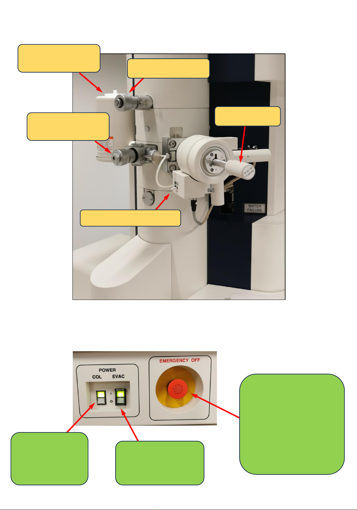
Power switch panel
2
EMERGENCY OFF switch
(should be used in case
of an emergency like
water leakage or fire
exposure). Special
procedure must be
followed for switching
on the system again).
EVAC power switch
(evacuation system).
Do not touch!
COL power switch
(high voltage,
lenses, deflection
system)
Goniometer switch panel
Sample holder
Condenser aperture
Objective aperture
(automized)
Cold fingers –only
used when needed
3
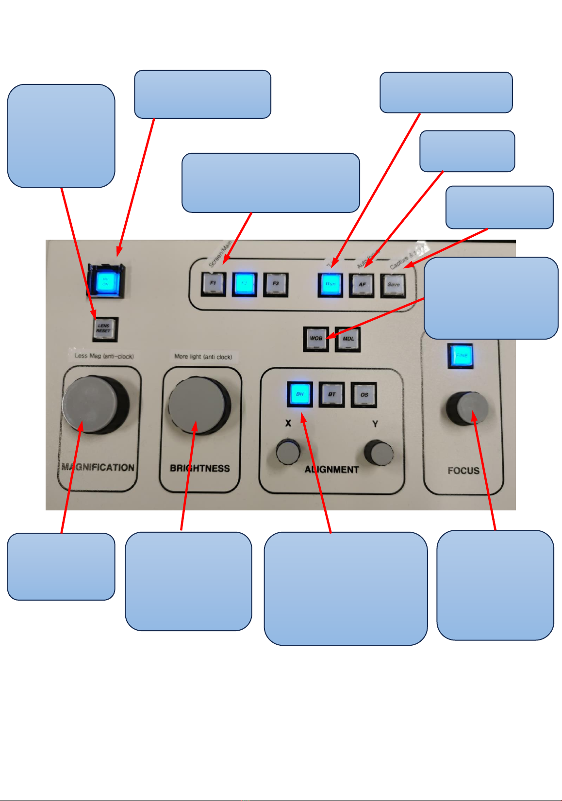
Control panel overview
Turn right for
lower
magnification
Ctrl brightness
and work on
the right side of
the crossover
BH (beam horizontal)
used for aligning
beam (with X and Y)
to the center of your
screen
Wobbler is used
to adjust for
eucentric height
or focus
Focus knob,
switch above
switches
between
fine/coarse
Resets
lenses (use if
you get lost)
to go back to
start
Turns off the
filament and HV
Switch between Screen
and Main camera
Goes to live mode
Auto focus
Captures and
saves image
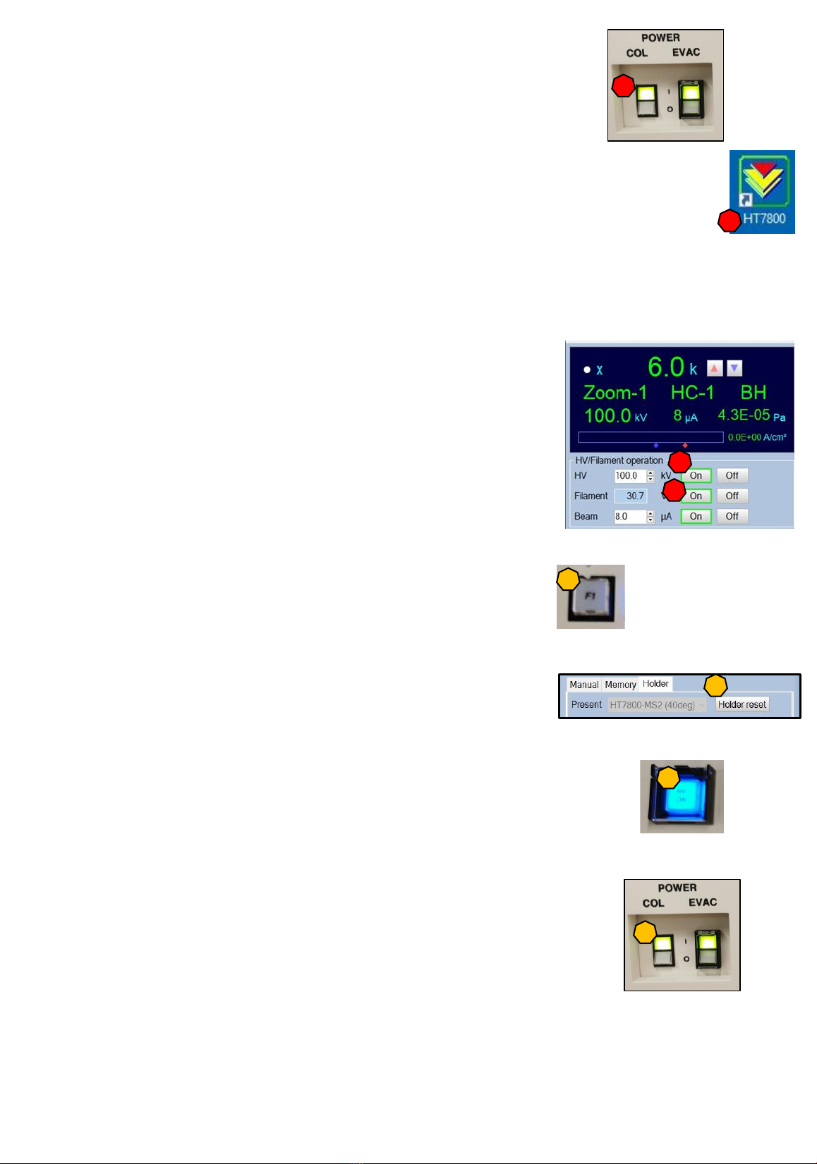
Start up routine
1. If the COL power is off, turn it ON
2. Turn on the computer and log in with password: mic77cim
3. Start the software. An initial screen will appear, and each control unit will be
executed. This window will automatically close, and the main control window
will be loaded.
4. Turn on the HV (normally we use 100kV) and wait until it reached 100kV (5 min).
This is a good time to prepare the holder with your samples (see page 5).
5. Insert the holder with your sample(s) (see page 6).
6. Turn on Filament and wait for it to stabilize ~ 30.3V (5 min).
The beam should turn on automatically as soon as the
holder is in PARK position. Do not change the Beam µA!
Shut down routine
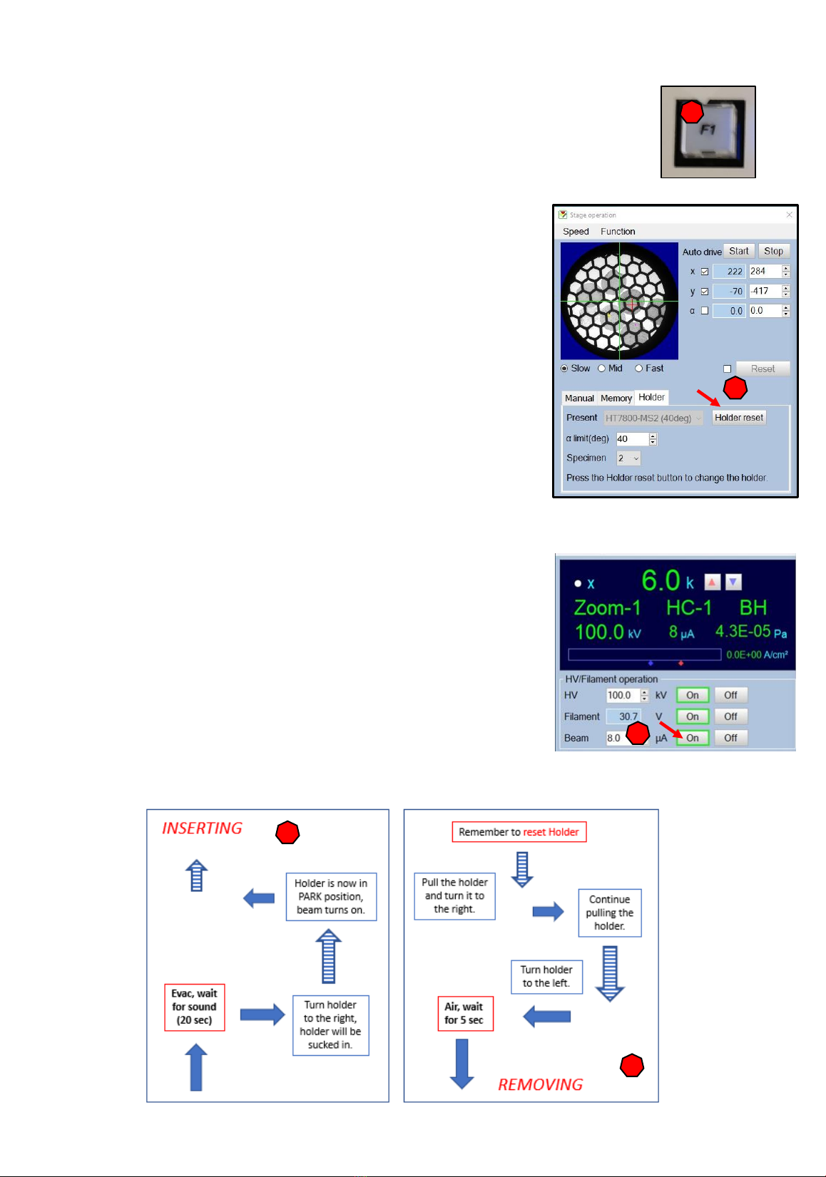
1. Go to the Screen camera (press F1).
2. Press holder RESET (stage operation window)!
3. Remove your samples holder. Place holder in the stand
and remove the grids. Insert holder and follow the
evac procedure to fully insert the holder.
4. Turn off “HV on” from the control panel.
5. Close the HT7800 software.
6. Shut down the computer (start menu + shut down).
7. Leave COL power ON (we turn it off during vacations).
8. Sign the logbook.
Breaks?
Turn off beam or place sample holder i PARK position if you need a 5 min break
Turn off filament if you need a lunch break 4
1
3
6
2
4
4
1
7
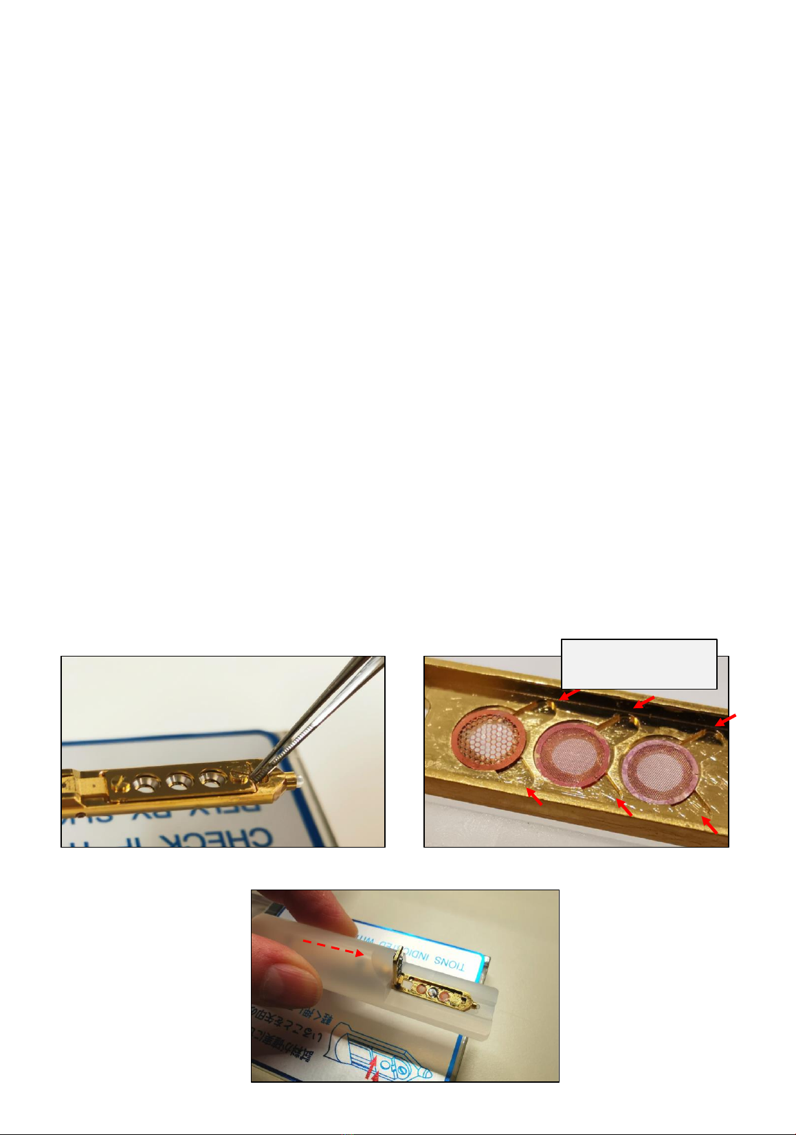
Mounting the sample is a delicate process and the sample holder needs to be handled with
great care. Please be especially careful to only load completely dry samples.
•The holder should have been left inside the column (without evac) away from dust.
Remove holder.
•Place the holder carefully in the stand. Make sure to never touch the area above the o-
ring. Place the silicon cylinder in position. Using the coarse tweezers, carefully lift the
metal lid. The MS2 holder can fit up to three samples at a time.
•Carefully place each grid inside the slot and make sure to note down the sample
position.
•Carefully close the top lid to secure the grids in position either with tweezers or by
pulling the silicon cylinder. Make sure there is no dust or excess of grease on the o-ring.
Holder - Sample mounting
5
1
2
3
Slits to facilitate the
removal of grids
To open, lift the metal lid Place samples in slots
Pull the silicon cylinder to close the metal lid

6
Inserting and removing sample holder
•Remove the sample holder from its stand. Insert the holder carefully and align the pin with
the opening in the goniometer. Push until it stops.
•Set the goniometer switch to “evac” (the evacuation of the prechamber starts).
•Wait for the beeping sound and the light to turn green.
•Gently rotate the holder towards the right, gently hold back when it is being sucked into
park position.
•Turn the holder to the left and let it go all the way in.
•The beam should now turn on automatically (if not, click on “beam”).
•To remove the sample holder, remember to do a “reset holder” in the software first.
•Pull the holder, turn right and when you reach the end, continue pulling out.
•Turn left and stop once you see the pin.
•Turn the switch to “air” and wait 5 sec before pulling out the holder.
•Once you have removed your grids from the holder, place it back into the opening (you
don’t need to evac and insert the holder).
Insert
holder
and press
Evac, wait
for sound
(20 sec)
Turn holder
to the right,
holder will be
sucked in.
Holder is now in
PARK position,
beam turns on.
INSERTING
Press Air,
wait for
5 sec
Turn holder
to the left.
Pull the holder
and turn it to
the right. Continue
pulling the
holder.
Remember to reset Holder
REMOVING
7
The process of exchanging samples
1. Switch over to the screen camera (press F1).
2. Go down in magnification.
3. Click holder reset in the stage operation
window.
4. Remove the holder by following the guidelines
(more info on page 6).
5. Place holder in it’s stand and carefully open top
lid and remove your samples. Place new grids in
the holder and close the lid (with tweezers or by
pulling the silicon cylinder).
6. Insert holder by following the guidelines (more
info on page 6).
7. The beam should come on automatically after
you have inserted the sample holder. If not, turn
on the beam.
2
3
1
5
6
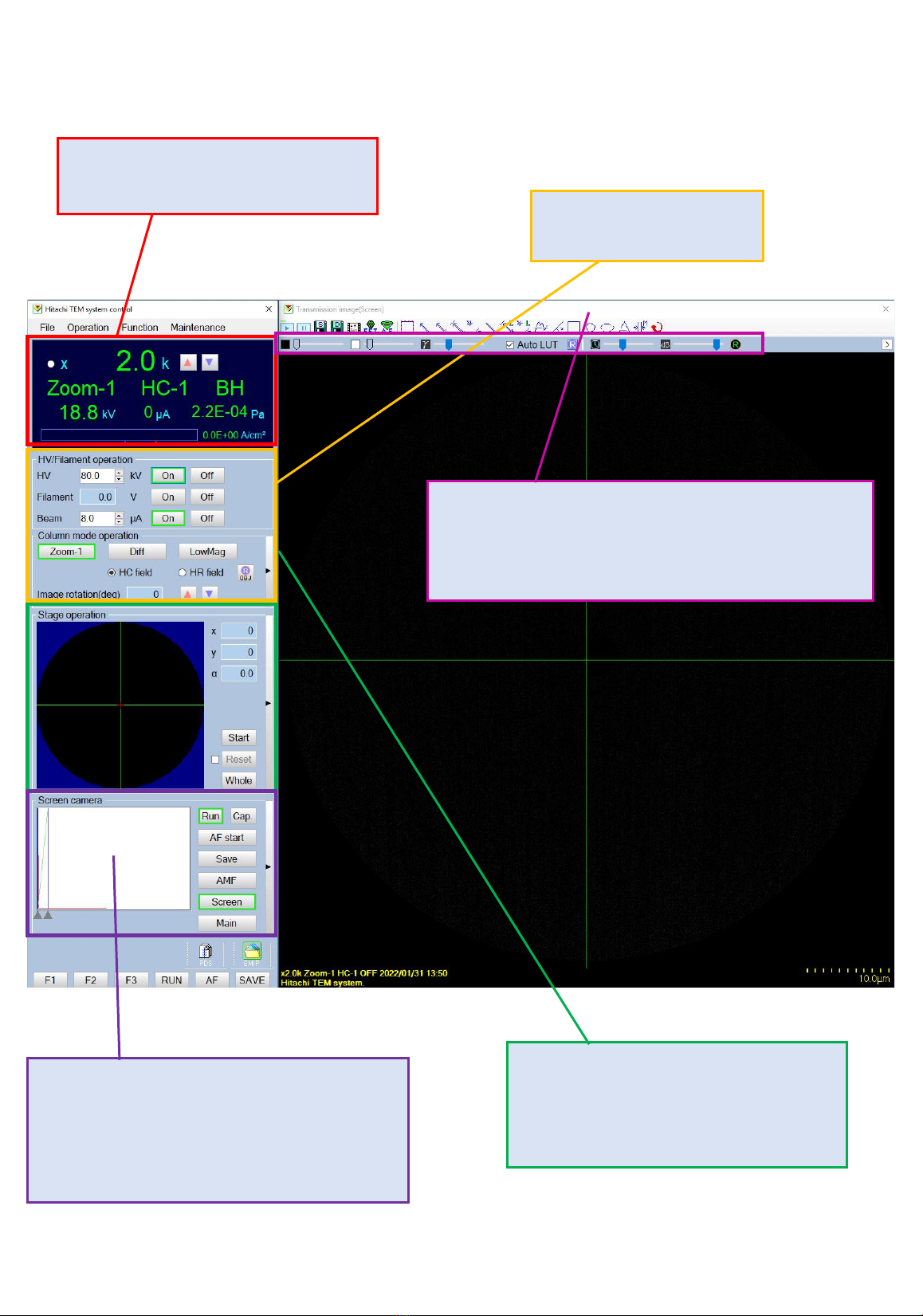
Information about magnification, kV,
filament V and vacuum condition Turning On/Off HV,
filament V and beam bias.
You will create a “whole” grid view here
and “click and start” to automatically
navigate to specific region.
Camera control (switch between
screen/main, autofocus and saving).
Histogram for chip exposure will show up
here –very useful.
You can adjust “live” camera exposure here as well as
black/white and gamma levels. The “R” will refresh
and “auto LUT” will automate the lookup table.
8
Software overview

How to start your imaging
Insert your sample holder and perform a beam shift horizontal alignment (page 17).
1. Open the Stage operation window.
2. Select the field mode you want to use (HC=high contrast, magnifies up to 200.000
or HR=higher resolution, magnification between 200-600.000).
3. Select the correct holder and specific holder position your want to image.
4. Open the camera operation mode.
5. Magnify to 5-6K. Focus you image by using the wobbler and carefully adjusting the
eucentric height with the screw.
5
4
3
1
6
9
2
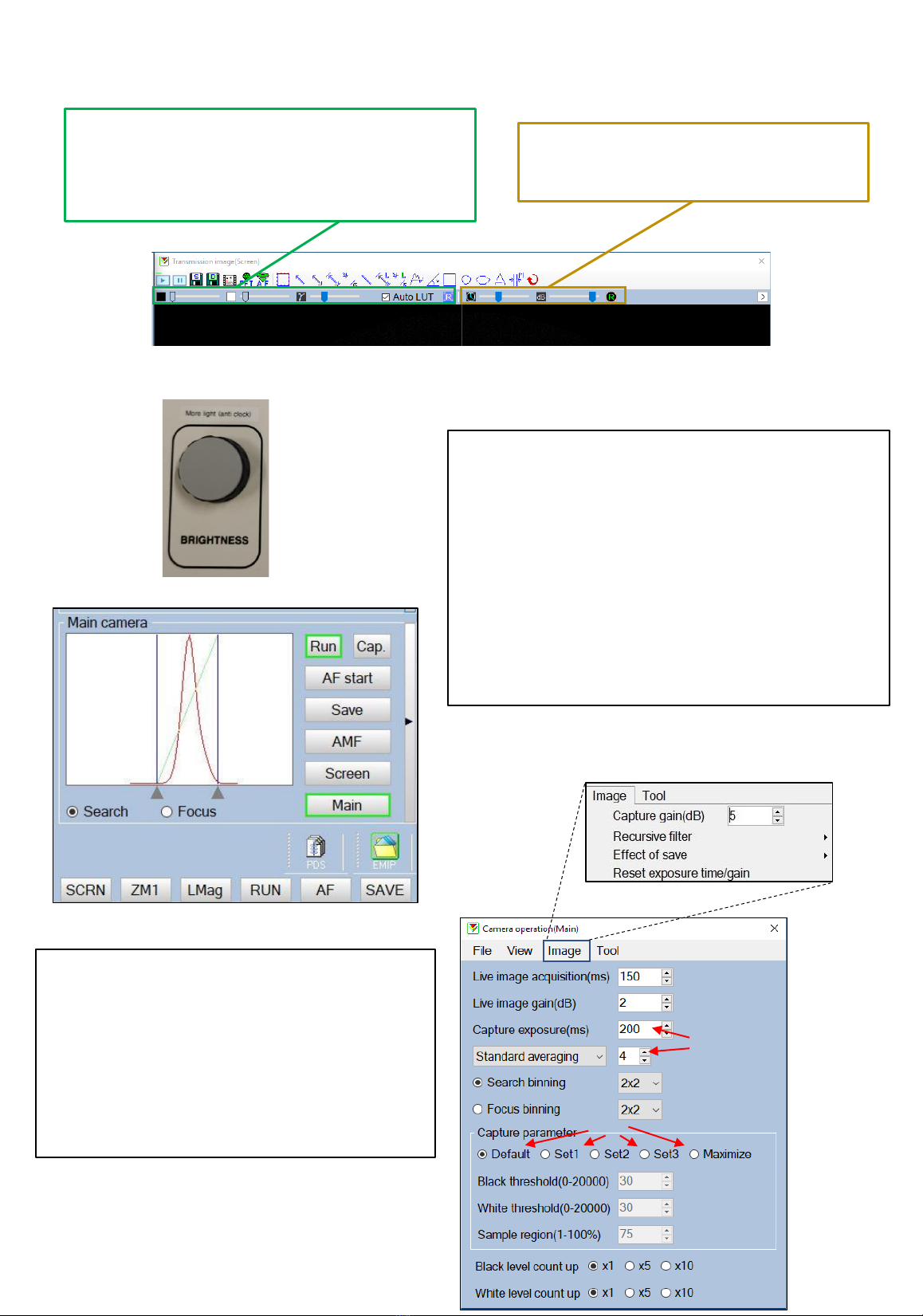
Adjusting image display and camera capture
The camera exposure and gain can be
changed for the live mode. “R” is to reset.
The camera display, white/black values and
gamma can be changed. If “Auto LUT” is checked,
the values change automatically.
•Increase the brightness in order to place the
spectra in the middle of the window (A).
•Set the standard averaging to 4-6 images and set
the capture exposure between 200-800 ms (B).
•Set the capture gain (C) to 2-6 (under “image”
window).
A
10
B
D
C
•Find your preferred “capture parameter” (D).
“Maximize” is imaging the whole camera chip
dimension. Default is very useful. Set 1 will
give more contrast (dedicated to HUS). Set 2
and 3 can be set up by any user.
A
To acquire images with high quality use the MAIN camera!
Table of contents
Other Hitachi Microscope manuals

Hitachi
Hitachi HF2000 TEM User manual

Hitachi
Hitachi TM3030Plus Specification sheet

Hitachi
Hitachi TM3030 Plus User manual

Hitachi
Hitachi S-4800 User manual

Hitachi
Hitachi TM4000 Specification sheet

Hitachi
Hitachi McDATA Sphereon 4500 User manual

Hitachi
Hitachi S-4100 User manual

Hitachi
Hitachi 3400-N Guide

Hitachi
Hitachi TM3030Plus Specification sheet

Hitachi
Hitachi TM3000 User manual

Popular Microscope manuals by other brands


VWR
VWR VisiScope 384 Series instruction manual

Nikon
Nikon ECLIPSE E200 POL instructions

Leica
Leica DI C800 User's manual & installation instructions

ThermoFisher Scientific
ThermoFisher Scientific Continuµm manual

ThermoFisher Scientific
ThermoFisher Scientific Continuµm manual

Olympus
Olympus SZ61 instructions