Hitachi 3400-N Guide

Using the Hitachi 3400-N VP-SEM
Before You Begin:
Sign in on the Calendar (we are pretty strict about this).
Wear gloves when handling anything that goes in the chamber such as stubs,
specimens, sample holders. Finger oils contaminate the machine and destroy image
quality.
Measure your sample’s diameter and height accurately:
Improper sample measurements will cause the sample to hit
the detectors and create thousands of dollars of damage!
Opening the Chamber to Load Specimens
(This may also be done later using the software)
1. Click the “AIR” button on the front of the machine
(push hard enough to hear vacuum change) (Fig. 1-A):
2. Wait a few minutes until you hear the machine beep
3. Insert sample holder. **For multi-holder, insert with
sample #1 facing blue pen mark in chamber**
4. Close the chamber and hold it shut with your hand.
Press “EVAC” button on front of machine (Fig. 1-B). Let go
of chamber door when vacuum engages it.
Starting PC-SEM:
5. Click the “PC-SEM” icon on the desktop. There is no
password.
6. When the PC-SEM finishes booting, you will see the
Specimen Dimensions window above (Fig. 2). Select the
correct Diameter/Size and Height (Fig. 2-A) for the
sample. Click OK.
7. On the right side of the screen are 4 overlapping control
panels -Condition, Image, Utility and Stage (Fig. 3). The
software will launch on the stage control panel as shown.
8. Check the other panels to be sure the last user left
this in the modes you want to use or you’ll have
difficulties and could damage your sample.
Figure 2. Specimen Size Setting
-A
Figure 3. Control Panels
EVAC AIR
-A B-
Figure 1. Front Panel Buttons

9. Go to the “Image” tab and choose SE (Secondary electron)
or BSE (back scattered electron) mode as
required/preferred. Standard imaging SE mode (Fig. 4-A).
10. Go to the “Condition” Tab and ensure the vacuum is set
to SEM mode ond not VP-SEM (variable pressure i.e. low
vacuum) (Fig. 4-B).
11. Go to the “Stage” tab (Fig. 5) and set the desired stage
height (z-position) (Fig. 5-A). 10 mm is a good starting point
which also works for EDAX. Use longer distance for more
depth of focus on uneven samples. Use shorter for higher
resolution. Click GO (Fig. 5-B).
12. Wait for specimen to reach desired height.
13. You can also use this panel to:
a. Rotate the sample (Fig. 5-C)
b. Tilt the sample (Fig. 5-D)
c. Move the stage by increments to find and centre your
features of interest (Fig. 5-E).
14. For Multi-Holder ONLY: If you are using the multi-
holder, click the “Memory” button (Fig. 5-F) in the lower
right corner of the stage tab. This Pop-up will appear:
a. The 6 positions are programmed in the pop-up
window (Fig. 6). Choose “Page 1”, then choose the
desired sample position. “No.1” goes to the first
sample if you took care to position the holder as
described when loading your sample.
b. Click “Move” (Fig. 6-A) to
go to that sample
position.
c. PLEASE DO NOT click
the other buttons on
this panel or you may
overwrite our program.
Figure 5. Stage Controls
-A
-D
-B
C-
E-
F-
Figure 6. Stage Memory-Multi Sample
-A
A-
B-
Figure 4. Image + Condition Tabs
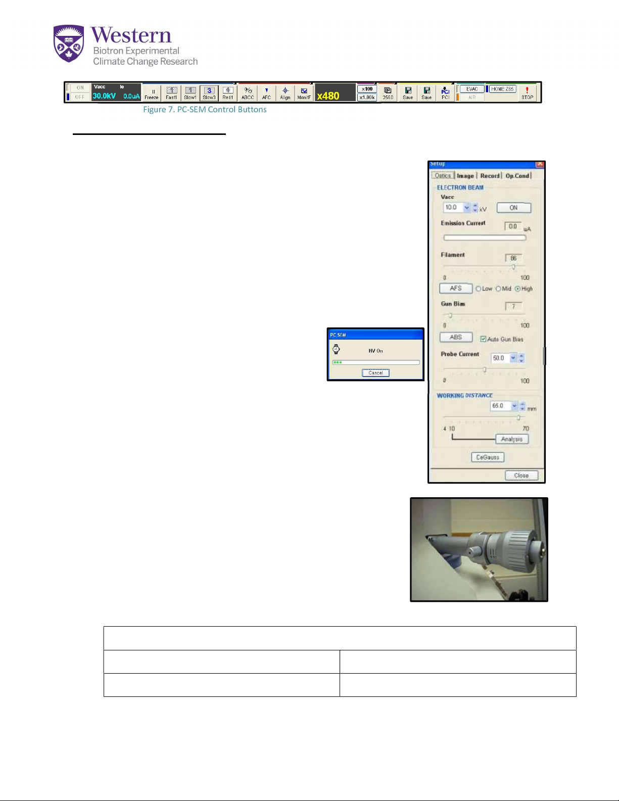
Electron Beam Setup:
1. Double click on the Beam Settings Frame (Fig.7-A) to open the settings window.
2. In the settings window (Fig.8), select the appropriate KV
(Fig.8-A) for your specimen.
3. Set the Probe Current (Fig.8-B) to ~50 to begin. Probe
current should be lower for very high magnifications
(>20,000x). Turn it higher for EDAX or long working
distances.
4. Set the Working Distance to match your stage height.
This is where the beam will come to a focus (Fig.8-C).
5. Once the chamber properly evacuated
and the HV warning disappears,
switch ON the electron beam (Fig.8-D).
Wait for the HV progress to complete
(Fig.9)
6. Click the AFS button (Fig.8-E) to auto-saturate the
filament so it emits a good electron flow. It should
deliver an emission current above 65-70uA (Fig.8-F).
7. Choose the Mechanical Aperture (Fig.10) recommended
for your sample and magnification (see us). You need a
higher number (smaller, 3-4) for high magnification
(above 10,000) and a low number (1—2) for very low
magnification (below 2000) or EDAX.
8. Turn Magnification to 100x using button at top of
screen (Fig.7-B), or using the manual dial by the
keyboard. You will use this to find your specimen and
start to focus.
Record Your Best Settings Here:
Aperture:
Kilovolts (KV)
Probe Current:
Stage Height/WD:
Figure 7. PC-SEM Control Buttons
A B
A
-
-
B
C
-
D
-
E
-
F
-
Figure 8. Beam Setup Panel
Figure 10. Mechanical Aperture
Figure 9. HV Progress
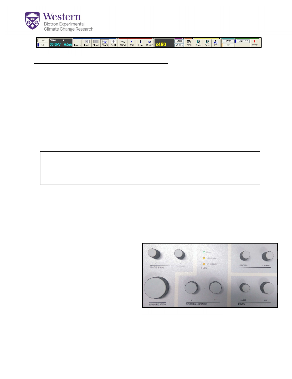
Focus, Brightness and Alignment Setup:
1. Click “Freeze/Run” (Fig.11-A) to start the scan if it isn’t running.
2. Click the ABCC button (Fig.11-B) to set Auto Contrast and Brightness. This is only a
starting point. Further fine adjustment controls are on the manual dial panel.
3. Use the “Fast 1” or “Slow 1” (Fig.11-C) scan speed settings to adjust focus so
the screen refreshes quickly. Clicking on the button twice makes it change from 1
to 2 (slower) USE SLOW 1 or 2 FOR BSE-you can’t see an image on “Fast”.
4. Once you see an image, turn the mechanical aperture (Fig.10) slightly to even out
the illumination across the image. If the image disappears, click ABCC again. If it
turns flat grey, go back to a lower aperture and do an alignment.
Alignments must be done whenever changing the KV, probe current, or
aperture size. Get our help. Refer to “Align the Instrument” (Appendix 1)
If you need to align the instrument, do it first between 2000-5000x, then repeat
again at 2x desired magnification.
5. Focusing your sample is a multi-step process:
a. Increase magnification on dial (Fig.12-A) slowly to desired level. If the image
moves, it isn’t properly aligned yet-repeat alignment. Adjust focus (Fig.12-B)
contrast (Fig.12-C), and brightness (Fig.12-D) as needed as you magnify.
b. To sharpen the focus -start by using the fine focus (Fig 12-B) to get the best
possible image. Using auto focus “AFC” (Fig.11-D) may help if you are close
to the focal plane.
c. Next, use Stigmator X
dial (Fig 12-E) – turn one
way and then the other to
find best image. Stop at
the best point.
d. Now repeat this using
Stigmator Y dial (Fig 12-F).
e. Adjust the fine focus again.
Repeat this process 2-3 times until you get the best possible image.
Unless you change the beam, stigmation is now complete. Using only fine
focus should work hereafter.
Figure 12. PC-SEM Control Buttons
A
B
C
D
E
F
Figure 11. A C B D
6. Adjust contrast and brightness for proper dynamic range
(good blacks, whites and greys). The ABCC button (Fig 13-A)
is a starting point only-increase contrast and decrease
brightness slightly from there using dials (Fig 12-C,D)
7. Click the desired scan speed: Fast (Fig 13-B) to scan your
specimen, locate areas of interest, and focus; OR Slow3/5 (Fig 13-B) to preview a
high resolution image prior to capture.
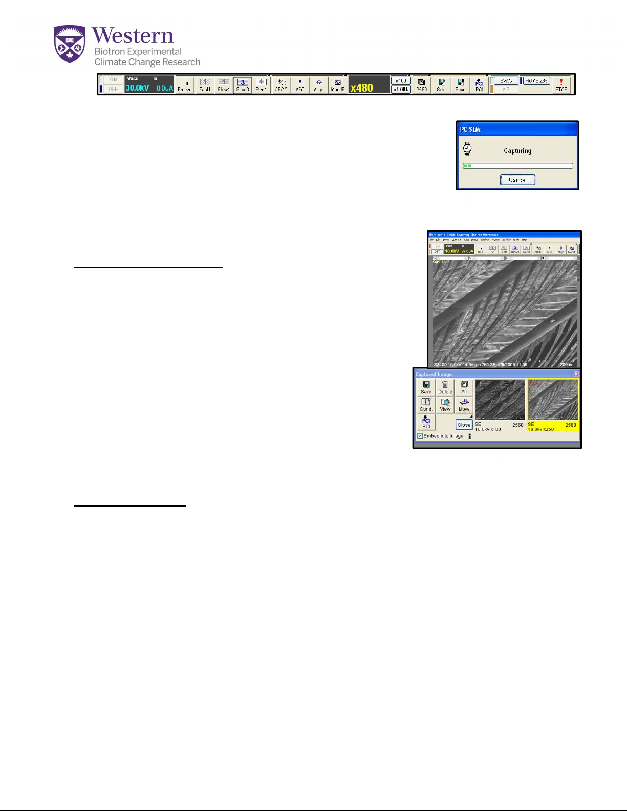
Capturing an Image:
1. You must be on Slow3/5 (Fig.13-B) scan mode before
you click the M/2560 button (Fig.13-C) to capture an
image.
2. The Capturing Image progress window (Fig.14) will open
and the image will gradually freeze, then the
Captured Image Window will open in the lower
part of the monitor as a thumbnail image (Fig.15-A).
3. The Image window will display CAPT (Fig.15-B) in the
upper left corner and the image is now frozen.
4. To return to live viewing, click “Freeze/RUN” (Fig.13-
D) and Fast again to reactivate the detector and move to a new spot.
Saving Images:
1. Select the thumbnails of those images you wish to save-see yellow (Fig.15-A).
2. “Embed into image” checkbox (Fig.15-C) will burn in annotations associated with
image. (To change what information is displayed on your image, go to Set-up –
Image Display – Record)
3. Click the “Save” button (Fig.15-D) – this will open a dialogue box.
4. Click “Select” in the saving pop-up window to find your folder first. (You have to
hit save again after naming the file-old software!)
5. DO NOT KEEP > 10-15 images open, or the software may freeze up. Save and
then delete them. Click All (Fig.15-E) then delete All to clear the RAM.
Figure 14. Capture Progress
Figure 15. Capturing & Saving
A-
-
B
-D
-C
-E
Figure 13. D B A C

Changing Specimens and/or Shutdown:
1. Click the HV OFF button in the upper left (Fig 16-A)
or on the beam control window (Fig 17-A).
2. Click the AIR button in the upper right (Fig 16-B).
3. The Specimen Dimensions window will open (Fig 18).
If you will be continuing, enter the dimensions of
your next specimen.
4. If you are shutting down, Select Size=15mm and
Height= Standard and click OK. The chamber will
open in about 90 seconds. (you will see a
“Processing to Air” message with stars that count
down to opening)
5. Using gloves or forceps, remove your specimen.
Change specimens now or leave sample holder in
drawer away from dust if you are finished.
6. Close the Chamber door and click the EVAC button
in the software (Fig 16-B) OR at the front of the
machine (Fig 20-A).
7. When the system has fully evacuated, begin
imaging again as before. You shouldn’t need to
realign the machine, but you will need to re-
saturate the filament if you are continuing.
8. IF YOU ARE FINISHED: quit the PC-SEM Program.
9. If you get a request to save the stage history, say “No”
10. Make sure that you sign out on the calendar.
11. Transfer your files using Dropbox NOT USB
12. Leave Computer ON and area clean
Figure 17. Beam Setup Window
A-
Figure 19. PC-SEM Shutdown
Figure
20
.
PC
-
SEM Shutdown
A-
Figure 18. PC-SEM Control Buttons
Figure 16.
A
B

APPENDIX 1: Align the Instrument:
If you change the mechanical aperture, the accelerating voltage or the probe
current, specific alignments of the instrument must be performed.
Mechanical Alignment:
-At the desired
magnification, first turn the
X-Align knob (Fig.A1-X) at the
side of the aperture control
until the beam reaches its
brightest.
-Hit “ABCC” to readjust
brightness.
-Repeat using Y-Align knob (Fig.A1-Y) on the end of the column. BE CAREFUL! You
can lose the beam entirely if you go too far. You must now perform the following
alignments:
Begin Beam Alignment:
-Begin with a magnification of 1000x –
5000x. Once you complete the alignment at that
zoom, repeat this whole process a second time at
twice your desired magnification.
-Apply the KV and probe current settings desired for
operation
-FIRST, perform normal focus and stigmation
operations without opening the align window.
The system must be relatively focused before
attempting to align it.
-Now open the alignment window. (Fig.A2)
-The functions of the “X and Y Dials” (Fig.A3-X,Y) on
your dial panel will change as you move down this
list of radio buttons to adjust various condensers and apertures.
Figure A1. Mechanical Alignment
-X -Y
Figure A2. Beam Alignment
X Y
Figure A3. Alignment Controls
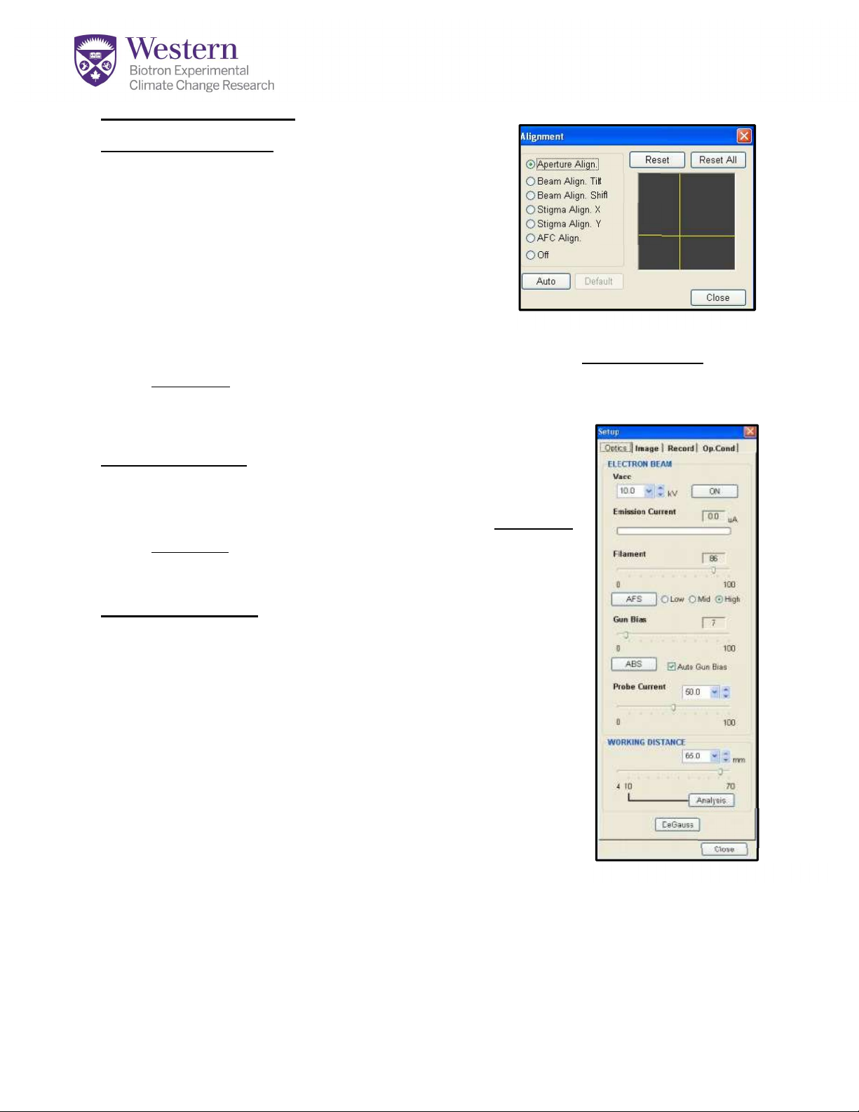
APPENDIX 1 continued
Aperture Alignment:
-Move to a distinct edge or small feature. And
activate “Aperture Align” Radio button. (Fig.A4-A)
-The “Wobbler” mode is activated to
exaggerate motion and assist you in aligning
the aperture. Using the “Red1” scan mode will
limit your vision and help you stay focused on
one location.
-Move the stigmator knobs on the Dial panel (Fig.A3-X,Y ) to minimize image
movement. Movement onscreen should appear to be a flashing motion in one
location-not a rocking motion. If you have to turn the dials too far, return to the
mechanical alignment adjustors first. (Fig.A1)
Beam Alignment:
-Select “Beam Align Tilt” (Fig.A4-B)
-Turn “X” and then “Y” stigmation knobs until maximum
brightness is achieved
-Repeat on “Beam Align Shift” (Fig.A4-C)
Stigma Alignment:
-If the beam has been running for awhile, you may need
to Degauss (Fig.A5-A) the image before beginning for best
results.
-Stigma Align X (Fig.A4-C): Adjust BOTH X and Y
stigmation dials (Fig.21-X,Y) to minimize rocking movement.
-Stigma Align Y (Fig.A4-C): Adjust BOTH X and Y
stigmation dials
-3rd Step: repeat as needed until image just appears to
move in and out towards you, not in X or Y directions.
-Close alignment window AND repeat Degauss step,
NOW-Repeat the Beam Alignment Procedure at 2 x Your Desired
Magnification for Best Results
Figure A5. Beam Setup-Degauss
-A
-A
}B
}C
Figure A4. Beam Alignment
APPENDIX 2: Using Variable Pressure Mode
This mode allows you to view uncoated, non-conductive specimens by suppressing
charging.
1. You will need a higher KV to use this mode, usually
10-25 KV with W.D. = 5-10 mm and probe current
above 50. You need lots of energy to view in this
mode as many electrons are lost to interfering air
molecules.
2. Before viewing on VP mode, set up the beam
first using a control sample on regular SE
mode-SEE APPENDIX 1 OR GET HELP. Focus, stigmate and align the
beam as for normal SE imaging.
3. Turn KV Off.
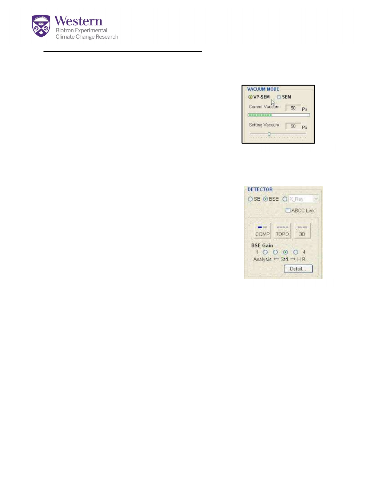
4. Under Conditions Tab, select VP-SEM. (Fig A6). The
syetm will automatically set itself to BSE mode now.
5. Set vacuum to 30-50. (Fig A6). Lower vacuum is more
efficient at charge reduction as air molecules absorb
some charge.
6. NOW evacuate the chamber and switch to the test
sample.
7. Turn KV back ON. You will need to focus on Slow 1
or Slow 2 mode. Fast is too noisy to see anything.
8. On the Image Tab adjust your BSE Gain setting (Fig A7) to 3 or 4 until you see
an image.
9. COMP mode highlights composition, TOPO highlights topography, and 3D brings
out 3-dimensional details. Going into the Detail window will open additional
controls of the 5 detectors used for BSE imaging.
10. DO NOT ADJUST STIGMATORS ON THIS MODE-use fine focus only!
Stigmation should have been done on the control sample first. Your focus will
become quite poor if you try to adjust this on BSE mode.
Figure A6.VP-SEM
Figure A7. BSE Controls
Table of contents
Other Hitachi Microscope manuals

Hitachi
Hitachi HF2000 TEM User manual

Hitachi
Hitachi S-4800 User manual

Hitachi
Hitachi TM3030Plus Specification sheet

Hitachi
Hitachi S-4100 User manual

Hitachi
Hitachi HT7800 User manual

Hitachi
Hitachi TM3000 User manual

Hitachi
Hitachi TM4000 Specification sheet

Hitachi
Hitachi S-4800 User manual

Hitachi
Hitachi TM3030Plus Specification sheet

Hitachi
Hitachi McDATA Sphereon 4500 User manual

Popular Microscope manuals by other brands


VWR
VWR VisiScope 384 Series instruction manual

Nikon
Nikon ECLIPSE E200 POL instructions

Leica
Leica DI C800 User's manual & installation instructions

ThermoFisher Scientific
ThermoFisher Scientific Continuµm manual

ThermoFisher Scientific
ThermoFisher Scientific Continuµm manual

Olympus
Olympus SZ61 instructions